Creating an Opportunity in the Mass Manufacturing of Wood-Based Furniture
←
→
Page content transcription
If your browser does not render page correctly, please read the page content below
Creating an Opportunity in the Mass
Manufacturing of Wood-Based Furniture
 Mechanical Engineering 310 Winter Design Document

                                        Team IKEA Industry
                        Annalisa Boslough, Hari Ganti, Taylor Uhl
                         Ana Fonseca, Cláudia Fontes, Pedro Neto

                            Mechanical Engineering Design Group
                                              416 Escondido Mall
                                              Stanford University
                                        Stanford, CA 94305-2203
                                       http://me310.stanford.edu
                                                c March 17, 2016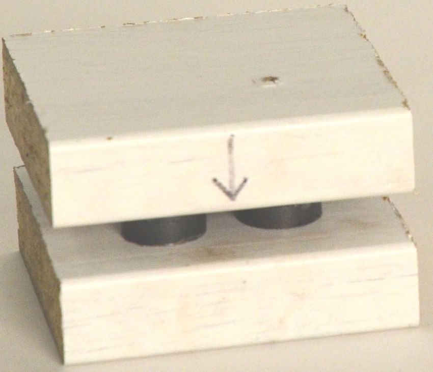
1 Executive Summary

            Figure 1.1: Our vision: Creating an opportunity in easy assembly.

    IKEA is best known for its ready-to-assemble furniture. But should this mean that users
commit hours to assembling the product at home? Users are voicing their frustrations with
the assembly times that come along with most IKEA products. Users can easily spend
several hours putting together a bed frame, a desk, shelving units, or other products. We
set out to decrease assembly times and the frustrations that accompany it by creating a
one-step assembly mechanism that can, in its current state, be applied to IKEA tables.
    Through our design of easier-to-assemble furniture, we have created overtãg for IKEA.
Value is added to the user by decreasing the time it takes for assembly. After all, time is the
greatest resource on earth. Our mechanisms utilize twist-lock and magna-lock mechanisms
to generate a rigid, intuitive, fast, and tactile experience for the user. The possibility for
this mechanism are exciting. We plan to build on our prototypes to generate a universal
fastener that can be applied to entire furniture lines for IKEA, which would result in both
a cost reduction to IKEA by way of decreasing breadth of hardware, and a value increase
to the end user through decreased assembly times. Furthermore, if this mechanism is void
of hardware, it holds the potential of being produced in a completely bio-based material,
further increasing the mechanism’s value to IKEA as a sustainability factor.

                                              2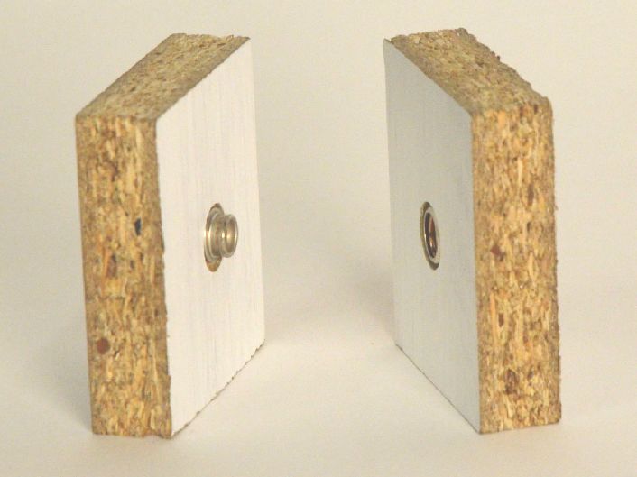
Contents

1 Front Matter                                                                                 2
  Executive Summary . . . . . . . . . . . . . . . . . . . . . . . . . . . . . . . . . .        2
  Glossary . . . . . . . . . . . . . . . . . . . . . . . . . . . . . . . . . . . . . . . . .   5

2 Context                                                                                      6
  2.1 Corporate partner: IKEA Industry . . . . . . . . . . . . . . . . . . . . . . .           6
  2.2 Need Statement . . . . . . . . . . . . . . . . . . . . . . . . . . . . . . . . . .       6
  2.3 The Design Team . . . . . . . . . . . . . . . . . . . . . . . . . . . . . . . . .        7

3 Design Requirements                                                                          11
  3.1 Functional Requirements . . . . . . . . . . . . . . . . . . . . . . . . . . . . .        11
  3.2 Physical Requirements . . . . . . . . . . . . . . . . . . . . . . . . . . . . . .        12

4 Design Development                                                                           14
  4.1 Concept Prototyping . . . . . . . . . . . . . . . . . . . . . . . . . . . . . . .        14
  4.2 Manufacturing Prototyping . . . . . . . . . . . . . . . . . . . . . . . . . . .          17
  4.3 Materials Prototyping . . . . . . . . . . . . . . . . . . . . . . . . . . . . . .        23

5 Design Specification                                                                         24
  5.1 Twist-Lock . . . . . . . . . . . . . . . . . . . . . . . . . . . . . . . . . . . .       24
  5.2 Magna-Lock . . . . . . . . . . . . . . . . . . . . . . . . . . . . . . . . . . . .       26

6 Project Management                                                                           27
  6.1 Money . . . . . . . . . . . . . . . . . . . . . . . . . . . . . . . . . . . . . . .      27
  6.2 Time . . . . . . . . . . . . . . . . . . . . . . . . . . . . . . . . . . . . . . . .     28

Bibliography                                                                                   30

A Appendices                                                                                   31
  A.1 Fall Findings . . . . . . . . . . . . . . . . . . . . . . . . . . . . . . . . . . .      31
  A.2 Early Winter Findings . . . . . . . . . . . . . . . . . . . . . . . . . . . . . .        32

                                                3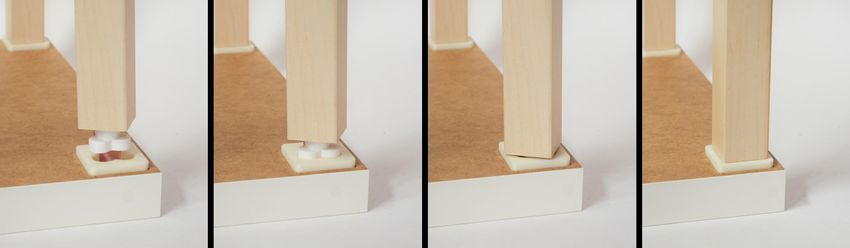
List of Figures

1.1   Our Vision . . . . . . . . . . . . . . . . . . . . . . . . . . . . . . . . . . . . . .                                                    2

4.1   Kliik Prototype Unfastened . . . . .     .   .   .   .   .   .   .   .   .   .   .   .   .   .   .   .   .   .   .   .   .   .   .   .   16
4.2   Kröss Prototype Assembly . . . . . .    .   .   .   .   .   .   .   .   .   .   .   .   .   .   .   .   .   .   .   .   .   .   .   .   17
4.3   Kløver with Red Indicator . . . . . .    .   .   .   .   .   .   .   .   .   .   .   .   .   .   .   .   .   .   .   .   .   .   .   .   19
4.4   Yellokløver Showing Lobes and Slot       .   .   .   .   .   .   .   .   .   .   .   .   .   .   .   .   .   .   .   .   .   .   .   .   20
4.5   Weittkløver Assembly Steps . . . . .     .   .   .   .   .   .   .   .   .   .   .   .   .   .   .   .   .   .   .   .   .   .   .   .   21
4.6   Hafmün Highlighting Single Magnet       .   .   .   .   .   .   .   .   .   .   .   .   .   .   .   .   .   .   .   .   .   .   .   .   22

5.1   Kløver Mechanism Detail . . . . . . . . . . . . . . . . . . . . . . . . . . . . . .                                                      24
5.2   Kløver Mechanism Exploded View . . . . . . . . . . . . . . . . . . . . . . . . .                                                         25

A.1 Fall Quarter Direction . . . . . . . . . . . . . . . . . . . . . . . . . . . . . . . .                                                     31
A.2 Fall Sound Prototype . . . . . . . . . . . . . . . . . . . . . . . . . . . . . . . .                                                       31
A.3 Early Winter Direction . . . . . . . . . . . . . . . . . . . . . . . . . . . . . . .                                                       32
List of Tables

6.1   Project Spring Budget . . . . . . . . . . . . . . . . . . . . . . . . . . . . . . . .                                                    27

                                                   4
List of Tables                                                                             5

Glossary
CNC “Computer Numeric Control,” an automated manufacturing process

FDM “Fused Deposition Molding,” a type of additive manufacturing (also known as 3D
   printing)

Hafmün Semi-circular, insert-based fastening mechanism, utilizing two magnets per leg

Kliik One-step mechanism prototype that utilized fabric snaps

Kløver Three-lobed, insert-based fastening mechanism, utilizing six magnets per leg

Magna-Lock Part of a family of mechanisms that is composed of an insert and a retainer.
   The insert locks in place inside the retainer due to magnetic forces

MDF Medium Density Fiberboard, a rigid and nearly isotropic material formed from com-
   pressed sawdust and binding polymers

Mycelium Rapidly renewable fungus material that forms the structural foundation and
    nutrient delivery system for mushrooms

Mycotecture Architecture grown from mushroom mycelium, coined by Philip Ross in
    2007

Overtäg Breakthrough or added value

RIFT Rigid, I ntiutive, F ast, T actile assembly

Twist-Lock Part of a family of mechanisms using an insert that slides into a receiver and
    twists to prevent the insert from sliding out

Weittkløver Prototype exploring a system-level integration of the kløver mechanism

Yellokløver High resolution kloøver mechanism to replicate a table leg / table top joint
2 Context
2.1     Corporate partner: IKEA Industry
IKEA is the leading wood furniture retailer in the world. Best known for their ready-
to-assembly, and most wood-based, furniture, IKEA is responsible for 1% of the world’s
commercial wood consumption. IKEA Industry is a subgroup within IKEA that directly
oversees the manufacturing of the wood-based furniture components that makeup IKEA
products. In addition, IKEA Industry is also responsible for exploring new production
capacities and opportunities to aid in IKEA growth. Forty-four global factories produce
wood-based products for IKEA, including a facility in Paços de Ferreira, Portugal, which
has an annual turnover of 170 million and exports more than 93% of its total production
[1].
     IKEA’s main focus is creating overtäg, which is Swedish for creating value to the con-
sumer. The most recent revolution in IKEAs mass manufacturing was in 1981, with the
introduction of board-on-frame construction. Board-on-frame utilizes a paper honeycomb
sandwiched between two wood composite layers to generate a rigid structure. This provides
an improved performance-to-weight ratio as compared with solid wood construction.
     What is the most pressing space for overtäg today? And more importantly, can it create
the next revolution in the mass manufacturing of wood-based furniture?

2.1.1   Corporate Liaison

                          João Neto - IKEA Industry AB Corporate Liaison
                          Title: Process Owner Maintenance
                          Project Management Office
                          Contact: joao.neto@ikea.com

2.2     Need Statement
It has been almost 35 years since IKEA’s last overtägt. IKEA is seeking alternative strate-
gies for a new opportunity in their manufacturing. Through our research, we have identified
two need spaces that could lead to the next revolution in the mass production of wood fur-
niture: assembly and sustainability.
    Through extensive need finding, benchmarking, user testing, and interviews, we have
identified a need for easier to assemble furniture. Users find the current assembly process

                                             6
CHAPTER 2. CONTEXT                                                                           7

to be complicated and time-consuming. Fundamental furniture pieces, such as desks, often
come with a few dozen different types of hardware, with total hardware counts in the
hundreds. This level of complexity sends assembly times and frustration levels for users
through the roof.
    Additionally, the state of the planet is in need of a sustainability revolution. A need for
recyclability of IKEA products is demanding attention. Sustainability efforts in manufac-
turing could result in end users recycling or composting their own furniture. Sustainability
could drive innovation.

2.3     The Design Team
2.3.1    Stanford University

                           Annalisa Boslough
                           Status: 1st year M.E. Graduate Student
                           Contact: boslough@stanford.edu
                           Skills: woodworking, metalworking, drawing, CAD,
                           energy modeling, and lifecycle analysis.

     In 2015, I received my B.S. in Sustainable Design Engineering from Stanford and
  am currently studying for an M.S. in Sustainable Design and Construction. Growing
  up in rural Alaska inspired me to work towards mitigating human impacts on the
  environment through design. I love working with my hands and immersing myself in
  team-based design projects. In my free time, I enjoy camping, fly fishing, and skiing.

                           Hari Ganti
                           Status: 1st year M.E. Graduate Student
                           Contact: hganti@stanford.edu
                           Skills: Prototyping/Machining, CAD/CAM, Mecha-
                           tronics, Testing Crazy Ideas

     I was born in Montreal, but grew up in Minnesota before moving to California to
  spend my undergrad at Stanford. I joined the Ski Team as well as the LSJUMB (Leland
  Stanford Junior University Marching Band), though the latter stuck with me a little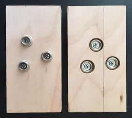
CHAPTER 2. CONTEXT                                                                              8

 better, and I still go to almost everything with the band. Im definitely an HBDI type-
 D person. I like getting a good grasp on the big picture and leaving the details up to
 people who are usually much more technically skillful. I love trying new (and crazy)
 things, and I have a healthy disregard for personal safety, but also a decent background
 working on projects from fuel efficient go-karts to haptic-fMRI capable robots, which
 helps me avoid too many unfortunate accidents.

                           Taylor Uhl
                           Status: 1st year M.E. Graduate Student
                           Contact: tuhl@stanford.edu
                           Skills: Solidworks, Matlab, Java, Julia, some
                           Arduino. Experience with welding, CNC milling,
                           3D printing, laser cutting, and other machining
                           processes.

     Born and raised in Eden Prairie, Minnesota. I attended the University of Minnesota
 for two years of undergraduate education before transferring to Stanford University
 to complete my B.S. in Biomechanical Engineering. I played varsity soccer during
 my undergraduate years Stanford finished 3rd in the country in my last season. My
 interests include product design, especially medical devices, fishing, soccer, water sports,
 hiking, and traveling.

2.3.2   Porto Design Factory

                           Ana Fonseca
                           Status: Architecture Graduate Student
                           Contact: anatri.fonseca@gmail.com

     I grew up in Aveiro, a beautiful city by the sea in center-north Portugal. After
 finishing high school, I went to the University of Coimbra to study Architecture, and
 during that period had the opportunity to spend one year abroad studying at the
 RWTH Aachen University in Germany, under the Erasmus Program. This experience
 broadened my horizons and after graduating I spend one year working in Hamburg at
 an architecture office. After this experience, I returned to Portugal to fund my own
CHAPTER 2. CONTEXT 9
company, which focuses on generative design processes and digital fabrication technolo-
gies. I enjoy embracing new challenges and team-oriented projects. I also love to travel
and am a bit of a foodie.
Cláudia Fontes
Status: Industrial Design graduate student
Contact: claudia.bfontes@gmail.com
I am an energetic Portuguese girl who is incredibly excited to join the ME310 team.
I finished my undergraduate degree at IPP in Industrial Design. I am passionate about
sustainability and designing products that are suitable in developing economies, helping
not just companies, but directly helping peoples lives. Over the years, my passion for
creating grew, as well as my commitment and dedication to emerging new challenges.
I have had a wide scope of education, in areas including theatrics, communication,
artistic production, product design and others, which have helped me to try new things
outside of my comfort zone.
Pedro Neto
Status: Civil Engineer
Contact: ec09147@fe.up.pt
Born and raised in Porto, Portugal, Pedro has a Master’s degree in Civil Engineer-
ing, specialized in Structural Engineering and Earthquake Engineering with a Erasmus+
internship at UCL (University College London) on the subject. Former Students repre-
sentative in the Civil Engineering Department at FEUP (Faculdade de Engenharia da
Universidade do Porto) and in the Pedagogic council of the faculty. Founder and CEO
of several startups and projects.CHAPTER 2. CONTEXT 10
2.3.3 Team Coach
Nik Martelaro
Status: 2nd year M.E. Graduate Student
Contact: nikmart@stanford.edu
Nik received his B.S. in Engineering Design from Franklin W. Olin College of En-
gineering before attending Stanford to pursue a masters in Mechanical Engineering:
Design Group. Nik has experience as a research assistant, working in collaboration
with Dr. Malte Jung and Dr. Pamela Hinds on projects ranging from human-team
robot interaction during high stress to participatory prototyping materials. Nik has a
passion for user research, need identification, persona creation, rapid prototype creation,
user testing, product design, and interaction design.3 Design Requirements
Our overarching goal for the quarter was to develop one-step assembly mechanisms for
fastening furniture, and we discovered many of our design requirements through iterative
user testing. After presenting users with our prototypes, we gained new insights into what
users expressed they wanted, and what they demonstrated they needed. Ultimately, we
chose four overarching goals that guided our design process:
• Rigid fastening
• Intuitive, instruction-free assembly
• Fast assembly
• Tactile experience
Using these four goals, we developed the user design requirements for our RIFT assembly
mechanisms. We also considered constraints IKEA Industry might face when manufacturing
our mechanisms, and developed additional requirements to help ensure our designs would
be viable for IKEA Industry. We found that physical requirements overlapped for both
IKEA Industry and our users.
3.1 Functional Requirements
3.1.1 End Users
Requirement Metric Rationale
The furniture must be rigid Our new mechanism must Maintaining the safety of
when fully assembled be at least as rigid as the furniture is a pri-
the existing mechanism for mary concern, and our new
the same joint (measured mechanisms should at least
through strength testing) meet the current load spec-
ifications
Our assembly procedure Users should be able to We found that users did
should be intuitive to users properly assemble furniture not read the provided in-
without requiring instruc- structions, and would often
tions incorrectly assemble furni-
ture, making it unsafe
The mechanism must as- Assembly time should de- Many users expressed dis-
semble quickly crease by an order of mag- satisfaction with extremely
nitude with our mechanism long assembly times
design
11CHAPTER 3. DESIGN REQUIREMENTS 12
During assembly, users Users should feel confident Bolts and other similar fas-
must receive clear feedback that each mechanism is be- teners typically have torque
when the mechanism is ing assembled correctly and specifications that users are
properly assembled is secured unlikely to know or use,
and users typically as-
semble furniture until it
“seems” right, instead of
when it is secure
3.1.2 IKEA
Requirement Metric Rationale
Any additional components Users should express the The new assembly mech-
should add more value than same or greater interest in anisms may add cost to
cost the furniture with the new producing furniture, but it
mechanism despite possible should not be greater than
increases in price the added value users per-
ceive
Devices (such as magnets) Our mechanism should not Aside from assembly, we do
used in our mechanism interfere with phones, com- not want our mechanism to
should not cause external puters, pacemakers, sil- affect the performance of
problems verware, laboratory equip- the furniture
ment, machinery, or any
other devices
New material has to be bio- Oil-based materials are not Compliance with IKEA
based and biodegradable allowed Group Sustainability
Strategy for 2020
3.2 Physical Requirements
Requirement Metric Rationale
The mechanism should use Parts that do not need to IKEA Industry is a wood-
primarily wood-based ma- be made from other mate- based furniture manufac-
terials rials (such as magnets, or turer, and it would be
high-grade bolts) should be preferable to integrate into
wood existing manufacturing fa-
cilities, as well as maintain
the aesthetic of the furni-
tureCHAPTER 3. DESIGN REQUIREMENTS 13
The modified furniture The modified furniture Packaging considerations
should maintain a minimal should not use more space are important to IKEA for
profile when disassembled disassembled than the shipping, as well as end
existing counterpart users, and the new mech-
anism should fit within
existing infrastructure
The mechanism should in- The product should be We would like our mecha-
tegrate well into IKEA In- made as similar to exist- nism to be able to replace
dustry’s existing products ing furniture designs to in- mechanisms across furni-
tegrate into product lines ture lines, rather than be-
ing constrained to a single
style
New material needs to Has to either weight less or To be in accordance with
improve either mechanical resist more load than the all dimensions of demo-
properties or weight of the current design cratic design
final product
3.2.1 Opportunities
Our prototypes thus far have been applicable only to IKEA’s LACK table. We look forward
to integrating with many more styles of IKEA furniture, and would like to expand to IKEA’s
entire range of furniture. Additionally, we are interested in integrating bio-based materials
to try and increase the sustainability of IKEA’s products while simultaneously improving
the user experience.4 Design Development
As we mentioned in our design requirements (Section 3), our focus on one-step assembly
led us to creating various RIFT mechanisms with a focus on:
• Rigid fastening
• Intuitive, instruction-free assembly
• Fast mechanisms
• Tactile feedback
4.1 Concept Prototyping
Prototype Photo Materials Question Insight Goals
Tested Gained Achieved
Kliik 1 Particle- Can we Users love 2, 3, 4
board and use a snap the snap
Fabric mecha- sound and
Snaps nism for feel, but the
one-step mechanism is
assembly? not rigid
Kliik 3 Plywood Can mul- Multiple 1, 2
and Fabric tiple snaps snaps make
Snaps increase fastening
rigidity? difficult, and
no longer
tactile
Tri-Mag Plywood Can mag- Magnets 2, 3, 4
and Mag- nets cor- are highly
nets rect for intuitive, and
alignment can provide
errors? a tactile
experience
14CHAPTER 4. DESIGN DEVELOPMENT 15
Kliik Twist Plywood, Can mag- Shear forces 2, 4
Fabric nets add overpower
Snaps, and rigidity magnets
Magnets to a snap easily and
mecha- the snap is
nism? difficult
Kröss Duron and Can a The mecha- 2, 3, 4
magnets twist-lock nism works
provide well, but
rigidity closer tol-
where erances are
magnets required
can not?
Kröss Ta- Duron and Do users Users like the 2, 3, 4
ble Magnets enjoy the experience,
experi- but require
ence of a more rigidity
twist-lock
table?
We began by exploring existing one-step fastening mechanisms, like backpack clasps,
fabric snaps, and collapsible umbrellas handles. Robust metal fabric saps led to the kliik
prototype, as seen in Figure 4.1; an attachment method for snapping two rigid parts to-
gether.
4.1.1 Kliik
Kliik tested the feasibility of fabric snaps in accomplishing our four goals. It was intu-
itive, fast, and tactile; however, the snaps did not lock into place securely enough for rigid
assemblies. A single fabric snap allowed significant play between the parts, and aligning
more than one fabric snap was difficult, even with the high precision of CNC milling. The
kliik mechanism with three snaps was more difficult to lock into place due to the slight
misalignment of snaps and their orientations in their respective plywood parts.
User testing of the kliik unveiled two insights. First, the feeling and audible click
of snapping two parts together was fun and satisfying. Second, the tactile and audible
experience of the kliik mechanism snapping into place provided users with intuitive feedback,
signaling that the parts were correctly assembled and fully secured. This discovery provided
the inspiration for our fourth goal of tactile feedback.
Further needfinding with our kliik prototype yielded another major insight. Our single-
snap kliik allowed parts to rotate freely while fastened, providing the inspiration for theCHAPTER 4. DESIGN DEVELOPMENT 16
Figure 4.1: Kliik prototype unfastened, showing the fabric snaps
successor to the kliik mechanism, the twist-lock mechanism, which was the first prototype
to fulfill all four goals of RIFT assembly.
Between the kliik and twist-lock mechanisms, we experimented with different ways to
create a tactile assembly experience. We shifted our focus from fabric snaps to magnets. We
experimented with using three magnets in place of the three snaps, and found that magnets
provided the same satisfying tactile experience as what we found in the fabric snaps.
4.1.2 Kröss
The kröss prototype, as shown in Figure 4.2 was our first test of both the twist-lock and
magna-lock mechanisms using inset geometry to constrain shear force and bending moments
on the magnets. It was also our first attempt at making a system level prototype with four
kröss mechanisms integrated into a prototype table. The retainer and insert were both
composed of stacked layers of laser-cut duron. Eight magnets, four in each the insert and
retainer, align when the insert is inserted into the retainer and twisted clockwise 45◦ . Fol-
lowing rotation, the lock and insert cannot be pulled apart without reverse rotation, as the
lobes of the insert have moved beneath an overhang that prevents them from being pulled
apart axially. This assembly also sustains shear forces and bending moments, providing our
first truly rigid RIFT prototype.
We decided to integrate our prototype into a functional system for user testing, so we
made three additional mechanisms and a table top to join them into a complete table,
similar in size to a LACK table. Our users found the mechanism compelling, emphasizing
the speed and intuitiveness of assembly. The best feedback we received was that the magnets
provided a reassuring sense of completion when the insert was rotated into place. Having
tactile feedback was our biggest improvement to the user experience in this prototype.
Unfortunately, users often remarked that it was not yet rigid enough to be a functional
table, so we set out to address these mechanical concerns with our next set of prototypes.CHAPTER 4. DESIGN DEVELOPMENT 17
(a) (b)
Figure 4.2: Kröss prototype showing insertion of insert into receiver
4.2 Manufacturing Prototyping
Prototype Photo Materials Question Insight Goals
Tested Gained Achieved
Kløver Acrylic, Can we The assembly 2, 3, 4
PLA, and create experience
Magnets parts with is very sat-
the re- isfying, but
quired the laser cut
tolerances, acrylic is too
but main- inaccurate
tain the
desired ex-
perience?
Yellokløver VisiJet Can ex- Yes 1, 2, 3, 4
(Acrylic- treme
like) dimen-
sional
accuracy
increase
rigidity?CHAPTER 4. DESIGN DEVELOPMENT 18
Weittkløver ABS, Mag- Do users Users unan- 2, 3, 4
Table nets, and prefer the imously
LACK experience preferred the
table top of assem- weittkløver
(card- bling the table, but
board, weittkløver rigidity issues
MDF, table to a persisted
chipboard) standard
LACK
table?
Hafmün ABS and Can reori- Two re- 1, 2, 3, 4
Magnets entation oriented
of the magnets is
magnets as strong
increase as six mag-
strength nets, while
and de- decreasing
crease cost, and
cost? improving
scalability
Our concept prototyping solidified the experience we wanted to create for users, but
left us with the challenge of finding a way to address the rigidity concerns of our early
prototypes and find improve the manufacturability of our devices.
4.2.1 Kløver
The intent of the kløver prototype was to test improvements to structural rigidity through
design and material changes. While the kröss used a four-lobed geometry, the kløver pro-
totype has three smaller to better align with the aesthetic of a LACK table. This also
increased the angle of rotation from 45◦ to 60◦ , allowing for greater overlap of the insert
lobes against the interior faces of the retainer. An added benefit is that it uses two fewer
magnets than the kröss mechanism does. Figure 4.3 shows the original prototype with red
coloring the longer lobe. The longer lobe was our attempt to create a one-way fit between
the insert and the retainer.CHAPTER 4. DESIGN DEVELOPMENT 19 Figure 4.3: The kløver prototype uses one longer lobe so it only fits one way, indicated by the red
CHAPTER 4. DESIGN DEVELOPMENT 20
We also modified our materials in this prototype. Our first prototype still used laser
cutting, but in acrylic, to reduce friction between the insert and the retainer. We used
FDM printed insert pieces to achieve tighter tolerances. While our parts still required
cleaning, they fit together well, which enabled us to retest our previous users to see if we
had improved on rigidity. We had successfully maintained the intuitiveness, fast assembly,
and tactile experience we previously achieved, but our users still felt that the rigidity factor
was concerning.
4.2.2 Yellokløver
This prompted us to create the yellokløver, in which both the insert and retainer were
3D printed in extremely high-resolution. The design of yellokløver is the same as that
modeled in Figure 4.4 with uniform legs rather than the single unique leg of the kløver
prototype. The print yielded tight enough tolerances to provide exceptional rigidity of the
joint. This rigidity was equal to or greater than the rigidity of conventional LACK table
legs. This outcome was a critical breakthrough in our design process because it proved we
could achieve necessary tolerances for structural rigidity.
Figure 4.4: The Yellokløver uses symmetric lobes, like the Kröss, but only three, iterating
on the kløver design
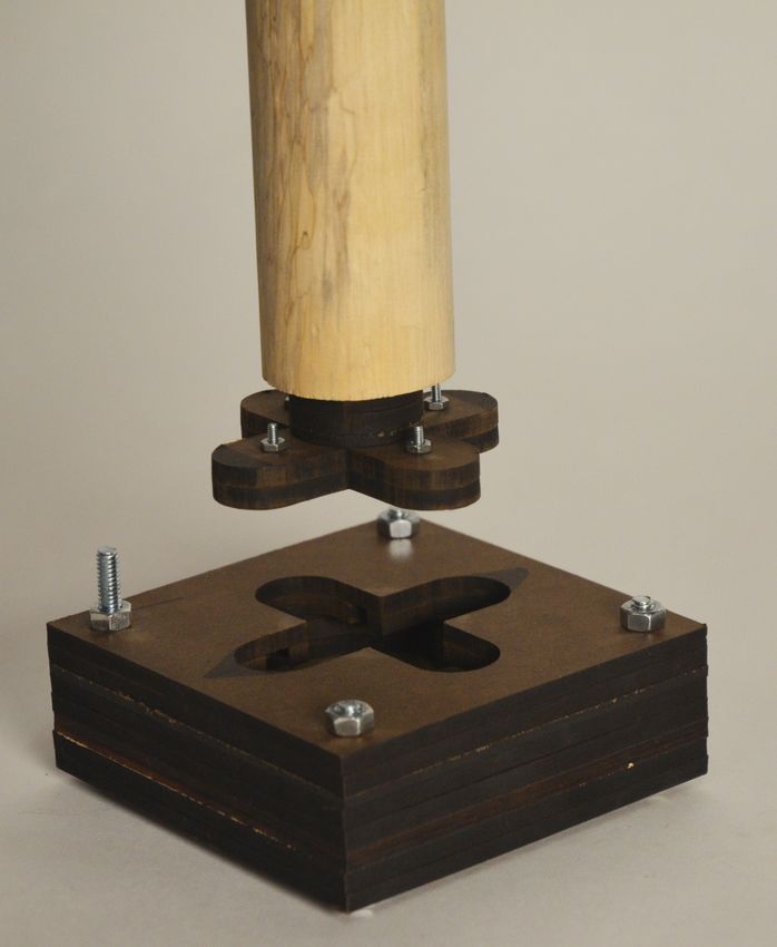
4.2.3 Weittkløver
As with our concept prototyping, the next step was for us to test a system level prototype.
We were not able to print additional yellokløvers for a complete table, but we were able
to use high resolution FDM parts than we previously used. We were also able to downsize
the design so that none of the mechanism was visible after insertion; a feature new to this
prototype. Four of the weittkløver, along with a LACK table that was CNC milled to houseCHAPTER 4. DESIGN DEVELOPMENT 21
the four receiver parts, formed our first successful modified LACK table, with its assembly
seen in Figure 4.5.
Figure 4.5: Weittkløver integrated into a table, demonstrating its simple assembly mecha-
nism
After color coding the lobes to ensure that users could easily align the legs to the table
when the legs were rotated, we once again put our prototype in the hands of users. We
asked users to build a conventional LACK table, as well as our modified LACK table.
We timed and observed the assembly process, and asked what perceptions they had about
the difference in the assembly mechanisms, to which we received unanimous praise for the
Weittkløver mechanism. Users felt that it satisfied all four of our design goals. Users found
the table to be rigid enough to be functional, users did not need to refer to (or even ask for)
instructions, users were able to assemble the table thirty times faster than a conventional
LACK table, and all users enjoyed the tactile experience of assembly. This marked another
successful RIFT prototype.
While we were satisfied with this prototype, we knew that improvement was necessary
in order to expand the scope of the mechanism (Section 3). Specifically, we wanted greater
rigidity, equal to or greater than a normal LACK table, and lower cost to manufacture.
4.2.4 Hafmün
Testing the weittkløver marked the end of our kløver mechanism iterations, but we designed
another notable mechanism that we plan to iterate on further. The kløver mechanisms all
used six magnets, and we had received a lot of feedback that magnets would increase the
cost of our mechanisms compared to IKEAs standard fittings. In doing research about
magnetic attraction and strength, we realized the kløver twist-lock mechanism was not
utilizing the full strength of the magnets. Magnets are great at resisting forces along the
axis of magnetization, but they do not do well with shear forces along the same axis. The
kløver mechanism locks as a result of magnetic attraction between two magnets, and is
unlocked because shear force overcomes the magnetic attraction. We realized that we were
under utilizing the strength of the magnets by orienting them in a non-idea plane. This
realization inspired us to design a mechanism that optimized magnetic strength relative to
the orientation of magnets in the joint and a table, which led us to the hafmün design.
The hafmün design has vertically aligned magnets, as compared with the horizontally
aligned magnets in the kløver mechanisms. The hafmün mechanism is still a twist-lockCHAPTER 4. DESIGN DEVELOPMENT 22 mechanism, but only needs two magnets to achieve the same twist-lock strength (Figure 4.6), as opposed to six magnets in the kløver mechanisms. Our initial testing is promising, and the hafmün design will allow us more freedom in size and cost. Figure 4.6: The Hafmün mechanism showcases the single magnet required by the insert, compared to three magnets for kløver designs
CHAPTER 4. DESIGN DEVELOPMENT                                                         23

4.3    Materials Prototyping
While the Stanford team has been developing one-step assembly mechanisms, the Porto
Design Factory team has been cultivating novel materials for use in IKEA furniture and
packaging, to replace synthetic materials with fungi-based biomaterials. Part of our fall
vision (Appendix A.1) was to explore sustainability in IKEA furniture, which the Porto
team was able to do by growing fungi to replace the petroleum-based materials (such as
polystyrene) used in IKEA packaging, and possibly replace engineered wood composites
(such as MDF) in IKEA furniture. We identified Mycellium as a material that is instru-
mental to Mycotecture. This fungus could displace IKEA Industry’s current wood waste
by consuming it, thereby converting a waste product that would otherwise be burned, into
a sustainable biomaterial.
5 Design Specification
We designed our mechanisms to meet our four major requirements:

   • Rigid fastening

   • Intuitive, instruction-free assembly

   • Fast mechanisms

   • Tactile feedback

5.1     Twist-Lock
We designed the twist-lock mechanism to handle the first three requirements. The twist-
lock mechanism is a two part design, where one part acts as a stationary receiver, and
the other as removable insert. The insert is able to freely slide into the receiver until it is
inserted fully. Twisting the insert causes it to rotate until it hits a stop, at which point, the
insert is retained in the receiver and cannot slide out without first twisting in the reverse
direction, as seen in Figure 5.1.

                           (a)                                    (b)

Figure 5.1: The Kløver mechanism is rotated from the unlocked configuration (a) to the
locked configuration (b)

    This type of mechanism can provide rigid fastening by constraining movement along the
axis of rotation, as well as resistance to bending through its contact surfaces on the interior
of the retainer. User testing has proved this type of mechanism to be intuitive. Users
were able to understand our mechanism almost immediately, with no prior training. Our
mechanism’s tight rotation angles and low friction resulted in quicker assembly as compared
with the conventional screw-in assembly to fasten LACK legs.

                                               24
CHAPTER 5. DESIGN SPECIFICATION 25 Figure 5.2: The exploded view ofthe kløver mechanism shows how the magnets align when locked, and the rotational axis to lock and unlock the insert (red dashed line) 5.1.1 Kløver The kløver mechanism in Figure 5.1 uses lobes to prevent the insert from being withdrawn once it is twisted in the retainer. The size of the lobes, and the number of them, varies across our prototypes, ranging from four large lobes in the original kløver, to three smaller lobes with one slightly longer to act as a one-way fit, to three small lobes that completely hide the slot when the leg is fully locked in place. Four lobes provided 45◦ of rotation from unlocked to locked positions, which required a larger lobe to have enough contact area for force distribution. The three lobed design allows for 60◦ of rotation, which allows a smaller lobe to be used since the forces can be distributed over a larger surface area. 5.1.2 Hafmün The hafmün mechanism deviated from the kløver mechanism in that it uses a single, large, semi-circular lobe. This slides in a semi-circular slot and is able to rotate 90◦ , but provides nearly equal contact area to the three-lobed kløver design. It is intended to reorient the magnets so their strength is better utilized, reducing the number of magnets needed for a successful magna-lock mechanism.
CHAPTER 5. DESIGN SPECIFICATION                                                          26

5.2    Magna-Lock
The magna-lock mechanism is complementary to the twist-lock. They work in conjunction
to create a RIFT assembly mechanism. The magna-lock mechanism completed the tactile
component of a RIFT assembly, and adds to the rigidity as well. The magnets initially
provide a slight torque on the insert when it is in the receiver, encouraging the user to
turn the insert piece. The magnets then assist in rotation, locking into place when they
are aligned. Because the insert must be rotated the opposite direction to release the insert
from the retainer, the magnets resist this rotation, increasing rigidity.
6 Project Management
6.1     Money
6.1.1   Winter Spending
Our total spending is $546 (fall) + $2670 (winter) = $3216.

We spent $2670 this quarter. The breakdown of the budget is as follows:

   • $150 (budgeted $250) ... Critical Experience Prototype

   • $250 (budgeted $500) ... Dark Horse Prototype

   • $270 (budgeted $500) ... Funky Prototype

   • $1500 (budgeted $500) ... Functional Systems Prototype

   • $500 (budgeted $500) ... SUDS

We came in over our projected winter budget of $2250 by $420. However, we did stay within
the broader ME310 course goal of spending $3000 during winter quarter. As seen in the
budget breakdown, we were on track to come in under-budget until the Functional Systems
Prototype. Having to outsource several 3D-printed parts quickly turned into lots of dollar
signs. Moving forward, we will need to be aware of this and allocate resources accordingly.

6.1.2   Spring Spending Plan
With an overall budget of $8000, we have ($8000 - $3216) = $4784 to spend over the course
of the final quarter. We will need to budget out $500 for SUDS again, and also plan for
unexpected hiccups along the way. Our project Spring budget is outlined in Table 6.1

  Project                      Launch                        Duration      Budget (US
                                                             (days)        dollars)
  Convergence                  Friday, March 18th            5             n/a
  Hunting Plan                 Tuesday, March 29th           9             100
  Part X                       Tuesday, March 29th           16            1000
  Manufacturing Plan           Tuesday, April 5th            16            400
  Penultimate Review           Tuesday, April 19th           30            1500
  Miscellaneous Spending       n/a                           n/a           500
  Safety Net Spending          n/a                           n/a           750
  EXPE Rehearsals              Tuesday, May 31st             1             n/a
  Spring Presentation          Thursday, June 2nd            1             n/a
  Spring Design Documents      Tuesday, June 7th             n/a           n/a
  SUDS                         Thursday, May 19th            1             500

                           Table 6.1: Projected Spring Budget
                                            27
CHAPTER 6. PROJECT MANAGEMENT 28
As outlined in the table above, we have allocated a specific dollar amount to each task
for spring quarter. We have $500 set aside for miscellaneous spending, in addition to a
safety net spending of $750 that is only to be used in the final two weeks of the quarter,
and only in the case of an emergency.
6.1.3 Lessons Learned
Shipping fees for next-day arrival really add up. We spent $200 (10% of our budget) on
shipping fees this quarter.
Outsourcing low-volume, high-resolution parts is expensive. We will need to explore ways
to manufacture high-resolution prototypes on campus in order to stay on budget.
It is important to have designated roles. We fell out of our responsibilities at some points
in the quarter, and plan to get back on track this spring:
• Hari ... Chief Communications Officer
• Annalisa ... Chief Documentations Officer
• Taylor ... Chief Financial Officer
6.2 Time
6.2.1 Outsourcing Manufacturing
We came across the dilemma this quarter of balancing time and money. We needed high
resolution printed parts, and we needed them fast. This left us choosing the fastest printing
and shipping options, which meant spending a lot of money to save time. This balance be-
tween time and money, our two major resources, was not perfect. We ended up exceeding
our budget for the quarter because of it. We would have saved over $200 if we had not spent
any money on expedited shipping, a number that would have gotten us close to finishing
the quarter on budget.
Moving forward, we plan to move away from outsourcing manufacturing as much as pos-
sible, and putting in more time and energy into manufacturing parts in our on-campus
facilities. Yet, in all likelihood, we will still need to outsource some of our prototyping, and
we will do our best to plan ahead so that we do not need the prototype within a couple of
days. This way, we do not need to pay $50+ in expediting costs.
6.2.2 Team
We prioritized team time as much as we could this quarter. We had weekly Skype meetings
with all six members of the design team. For a few weeks, we even had two Skype calls per
week in order to increase team communication. We also included our Corporate Liaison,
João, in one of our meetings to hear his take on our progress.CHAPTER 6. PROJECT MANAGEMENT 29 6.2.3 Convergence It is important that we define our direction while the whole design team is together in Porto from March 18th to March 22nd. We plan to complete a convergence workshop to aid in this process. After choosing a direction, bi-weekly communication between teams will be a must.
Bibliography
[1] Ana Maria Gonalves. Ikea de paços de ferreira conquista gesto das futuras fábricas do
    grupo na rússia. Technical report, Jornal Econmico, June 2015.

                                            30
A Appendices
A.1 Fall Findings
Figure A.1: Fall vision: Creating an opportunity in increasing perceived value
Fall quarter was dominated by benchmarking and user findings. We learned a lot about
the perception people have of IKEA, both good and bad. Most users desired for higher
end furniture that would last longer and look nicer. Maybe IKEA did not have the budget
to put more cost into their furniture, but that does not mean the aesthetics could not
be improved. We set out to create a line of furniture that created ”artificial elegance,”
illustrated in Figure A.1. The users valued the furniture higher, but the cost to manufacture
remained the same. We tried to achieve this in many ways, including altering the sound of
a table top by replacing its airy interior with spray foam, as shown in Figure A.2.
Figure A.2: Replacing the honeycomb interior of a LACK table with spray foam to create
a solid wood sound
31APPENDIX A. APPENDICES 32
While the upgraded furniture line was unsuccessful, it sparked our thinking of new
materials. New materials can lead to innovation. Perhaps this innovation is not in perceived
value by way of artificially adding value, but rather by adding a factor of sustainability.
What if we could find cost-effective materials that would inspire customers to purchase
more furniture?
A.2 Early Winter Findings
We set out to answer this question through the development of our peanut chair. Using
biodegradable peanuts, we attempted to create a completely sustainable furniture piece
that would allow the user to form it into any shape, adding modularity. The user purchases
a bag full of compact peanuts, and this bag can be expanded or compressed to any comfort
level with a household vacuum. Figure A.3 shows a molded chair that was created with
this prototype.
Figure A.3: Moldable furniture using packing peanuts and vacuum-sealed bags, our early
winter direction
Ultimately, the chair was not formable enough to allow for true modularity. Yet, the
idea of generating a sustainable piece of furniture was exciting, and inspired the current
research of bio-based materials.You can also read