Blinking Orbital Prosthesis - UW-Madison
←
→
Page content transcription
If your browser does not render page correctly, please read the page content below
Blinking Orbital
   Prosthesis
    Client: Gregory G. Gion, MMS, CCA
           Medical Arts Prosthetics

    Advisor: Professor Thomas Yen, PhD
     University of Wisconsin - Madison

            Leader: Bret Olson

      Communicator: Justin Cacciatore

         BWIG: Michael Konrath

          BSAC: Blake Marzella

                    1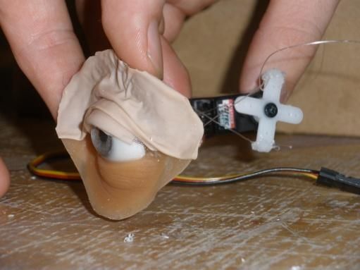
Table of Contents

Abstract…………………………………………….………………………………......…3
Introduction…………………………………………..……………………...………...…3
Background………………………………………..……………………………………..3
      Problem Statement…………………………………………………………...…….5
      Problem Overview………………………………………………………..………..5
      Problem Motivation…………………………………………………………..……6
      Design Constraints……………………………………………………………..…..6
      Current Devices…………………………………………………………………....7
      Competition…………………………………………………………...…………...9
Potential Designs…………………………………………………………………...…...10
      Embedded Cord Tension Mechanism…….……………………………..………..10
      Micro Servo Motor…………………….…………………………………………12
      Memory Shape Alloy……………………………………………………………..13
      Artificial Muscles (EPAM)……………………………………………………….13
Design Matrix…………………………………………………………………………...15
Final Design……………………………………………………………………………..15
Testing…………………………………………………………………………………...16
      Positioning………………………………………………………………………..16
      Reliability…………………………………………………………………………17
      Assumptions and Inherent Limitations…………………………………………...17
Future Work………………………………………………………………………….…18
      Building a Patient-Ready Model……………………………………………….…18
      Integration & Production…………………………………………………………19
Summary of Ethical Considerations…………………………………………………..19
Appendices
      A…………………………………………………………………………………..20
             Consideration of Electromagnets……………………………………….…20
             References……………………………………………………….………...20
             Management Planning………………………………………………….…21
      B - Product Design Specifications…………………..……………………………22

                               2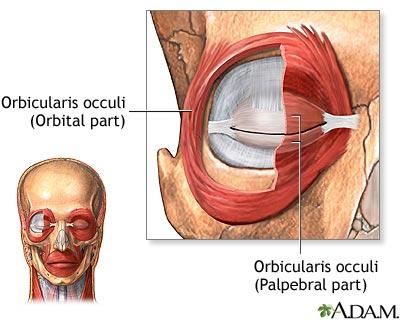
Abstract

       At the Medical Art Prosthetics Clinic in Madison, Greg Gion and his associates make
prosthetics for those who have lost their eyes due to an accident, disease, or genetic disorder. Mr.
Gion’s goal is to help the thousands of people who have an absence of facial tissue by restoring
their appearance and giving them greater self confidence. The problem with the current
prosthetics is that they are completely static, which makes them quite noticeable to the casual
observer. Our goal for this project is to create a prosthetic eye that has the ability to blink, and
therefore enhances the realism of the prosthesis as a whole. Through our research, we were able
to incorporate the function of the actual human eye muscles and a few existing designs to
develop an effective prototype.
Introduction
       A prosthetic is a medically fabricated device that serves as
an extension or replacement of a damaged body part in order to
restore functionality and provide the user with a more natural
appearance [1]. In the event where an individual experiences the loss
or surgical removal of an eye due to an injury, genetic defect, or
disease, the use of an orbital prosthesis restores the individual’s
natural appearance (Figure 1). However, while the current orbital
prosthetics promote an overall sense of restoration and realism, the
prosthetics lack the ability to simulate a human blink. It is this
static nature which prevents an orbital device from completely              Figure 1: Actual Medical Arts
restoring an individual’s appearance. We intend to design a                 Prosthetics Clinic Patient
                                                                            http://www.medicalartprosth
mechanism that will allow for an orbital prosthetic to blink in order       etics.com

to provide the appearance of functionality of a natural eye in conjunction with the already
realistic static appearance.
Background
       The development of an orbital prosthesis is regarded as both an art and a science, referred
to as anaplastology[2]. Each prosthesis must be custom made in order to provide the most
realistic and life-like appearance. As such, variances such as the individual’s skin tone, direction
of skin folds, skin texture, facial proportions and anatomical landmarks must all be taken into
                                                   3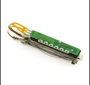
consideration[2]. The overall surface area of the prosthesis must also be taken into consideration.
For example, some individuals may experience the surgical removal of larger regions than just
the eye; regions such as the eyebrow, portions of the nose as well as parts of one’s cheek[1]. As a
result, an orbital prosthesis may include extensions to satisfy these areas, affecting the aesthetic
appearance. Great artistic skill is required in order to provide a prosthesis that smoothly
transitions from the organic tissue to the prosthetic material. These skills also aid in the
development of the prosthetic eye which must match its real equivalent in size, shape, shading,
and coloration. In order to satisfy the need for a natural prosthesis, these devices are commonly
made out of PMMA, or poly methyl methacrylate, and silicone[1]. The silicone composes the
fleshy portions of the prosthesis while the eye is composed of PMMA. A prosthesis typically
lasts an individual for upwards of two years and commonly needs to be replaced due to color
degradation and user wear and tear. Consistent cleaning and maintenance as well as the use of
sunglasses to slow the color degradation from UV radiation
exposure can extend the life of an orbital prosthesis [2].
       The making of an individual prosthesis commonly
begins by taking molded impressions of the empty orbital
cavity. This is done in order to accurately record the
anatomical features of the cavity which provide the basis for
the development of the prosthesis [2]. From this mold, a wax
prototype is created and sculpted. This is done in the
presence of the patient in order to integrate the patient’s        Figure 2: Development of realistic
                                                                   prosthetic eye
opinion into the prosthetic’s development[1]. Once a wax           http://www.medicalartprosthetics.com

prototype is accurately made which satisfies the client’s needs, pictures are taken of the client’s
skin surrounding the orbital cavity in order to assist in the development of prosthesis’ color tone.
At this point, a prosthesis is made out of PMMA and silicone and placed on the client. Here,
meticulous details such as freckles, blood vessels in the eye, hair, and the skin folds are made by
hand to help provide a more natural transition from the surrounding tissue to the prosthetic
material [1] (Figure 2). From this, the final prosthesis is made and delivered to the client.

                                                   4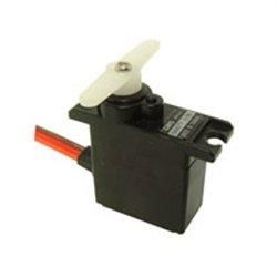
Problem Statement
       People of any age or gender may experience the surgical
removal of an eye due to an injury, genetic defect, or disease. The
use of an orbital prosthetic allows these individuals to gain a
sense of self-confidence and a more positive self-image.
However, while prosthetics have been developed to create an              Figure 3: Current prosthetic
                                                                         eye, showing the acrylic
incredibly realistic and aesthetically pleasing orbital device, they     eyepiece and PMMA material
have failed to provide the appearance of functionality of a real         separately.

eye. That is, the prosthetics are static and cannot blink. This is illustrated in Figure 3 as the
eyelids of the prosthetic remain in the same position even when the eye is removed. Our client
desires for us to devise a mechanism which would allow for a prosthetic eye to blink. This
mechanism will be used as a model in presentations to illustrate the blinking mechanism’s
effectiveness and potential for further development. As such, our design does not have to meet
the requirements for direct use for a client. However, we intend to expand upon our client’s
original goal and look forward toward the implementation of our mechanism into an actual
orbital device. That is, we aim to meet some of the basic requirements for function in an actual
orbital prosthesis through the development of our blinking mechanism. It is our hope that by
doing so, our blinking mechanism can easily transform from a working theory to the actual
implementation of our design for an individual’s use in a prosthetic. Only by developing a
mechanism through which an orbital prosthesis can blink can the steps toward developing a
complete orbital prosthesis, one that includes both a natural appearance and the appearance of
functionality, be undertaken.
Problem Overview
       In order to provide individuals who have undergone the total surgical removal of an eye a
complete orbital prosthesis, we intend to develop a mechanism which would allow a prosthetic
eye to blink. Our client’s main focus is to develop a mechanism that can be used in presentations
to demonstrate our design’s potential for further development. However, we are taking into
consideration the constraints and environment our mechanism would be exposed to should it be
developed into an actual prosthesis. We hope that by doing so, we can facilitate a smoother
transition from a presentation model to an implantable blinking prosthetic eye. In order to create

                                                  5
such a mechanism, it is imperative that we research the blinking mechanism of a normal human
eye. Our mechanism must be able to successfully recreate both the normal blink of a human eye
and its consistent performance throughout the day. We must also consider how our mechanism
is to be powered and how this power option could the affect the development of a later prosthetic
prototype.
Problem Motivation
People who experience damage to an eye due to trauma, birth defect or disease have two
options considering an orbital prosthesis. If only the eye is damaged, an ocular prosthesis is
used. However, if there is damage to the surrounding area, such as the eye lids or orbit, an
orbital prosthesis must be used. Patients who receive an orbital prosthesis do so to retain a
normal appearance. Ideally, these patients could live their lives and the people they encounter on
a daily basis would never know they had a prosthetic orbital device [1]. Anaplastolgists are able
to create a prosthesis that looks nearly identical to a human eye. However, there are factors that
limit the realism of their creations. One of those limitations is the prosthetic’s static nature. No
matter how realistic a prosthesis looks, it may become noticeable when the prosthetic eye fails to
blink. Our motivation for this project is to give back a sense of normalcy to these patients.
Design Constraints
There are essentially two sets of constraints for our design project. The first set of
constraints concerns our final goal of creating an implantable blinking orbital prosthesis.
Though this is not our primary goal, we are designing our device with these final constraints in
mind. Most obviously, the eye must be able to blink. It must also be able to do so at a speed as
close as possible to the actual speed of a blink, a rate of 200-300 milliseconds per blink. Since
this would actually be implanted into a person, there are size constraints. Each prosthesis is a
different size depending on the patient, so this design would need to fit in about the size of the
human eyeball, which has a diameter of about 25-29mm in order to accommodate all of them.
The prosthesis would have to be comfortable for the patients to wear on a nearly daily basis.
This means the design would have to be silent, not produce vibrations and relatively lightweight,
all of which would be bothersome for the patient. Most importantly, the design would have to be
safe. There would have to be no chance of electrical shock. Materials used would have to be
bio-compatible and non-allergenic and the prosthesis would need to be easily sanitized to avoid
complications such as infection. Current orbital prostheses already need to be replaced
6occasionally due to growth of the patient or wear [1]. Ideally this design would last as long as the
rest of the prosthesis. We decided that a lifetime of a year, with only minor maintenance, would
be reasonable. To achieve maximum realism, the prosthesis would need to blink synchronized
with the real eye. It would also need to do so reliably without failure.
Our primary set of constraints concerns the creation of a model to be used for
demonstrations. Therefore, these constraints focus only on the mechanical aspects of our
blinking mechanism. Our model will have to be able to blink upon request. If the demonstration
fails even once or breaks, the quality of the design will be questioned. Our design must also be
safe for the demonstrator to use. We will also be trying to keep our design as small and fast as
possible.
Current Devices
Currently, there are no blinking orbital prostheses on the market due to the fact that
current orbital prostheses are completely static. There are many different ways that the current
static prostheses can be attached. Osseointegration is one such attachment process where the
prosthesis is surgically attached to the bone of the patient. Another is the use of a pair of
magnets that can be attached to the bone as well as the prosthesis. Finally, the prosthesis can just
be attached using adhesives[1].
Our group took inspiration from current devices which aid in the blinking function of
patients with intact eyes. These devices are used to help patients with muscle paralysis, a
condition that prevents these individuals from blinking normally. This is done for cosmetic, but
more importantly, functional purposes as well. Since the patients still has a working eye, they
still need to blink in order to lubricate the eye. Our blinking orbital prosthesis would only need
to blink for cosmetic reasons as an artificial eye would have no need for lubrication. The
technique that is most similar to our project is research being done using EPAM (electroactive
polymer artificial muscle). Researchers in California have been working on using EPAM to
close the eyelid and the use of sling to open the eyelid. At least one patient has had this EPAM
technology successfully implanted [3],[4]. Another device called the Arion sling has been used in
the past to treat ptosis, a condition occurring when the eyelid sags lower than it should [5]. Other
methods, which are used to treat paralytic lagophthalmos, include the use of implantable gold
weights and palpebral springs. Gold weights, which are used much more commonly, are gold
implants that weigh the eyelid down due to gravity, but are light enough where the patient can
7still open their eyelid using their own muscles. Palpebral springs work in a similar fashion, only
instead of relying on gravity, the force of a torsion spring closes the eye. The palpebral spring is
rarely used as it is more invasive than the gold weight implant, but is favored by some since it
doesn’t depend on gravity [6]. While these designs aren’t used in orbital prostheses, there is some
potential for the incorporation of these concepts into the development of our blinking
mechanism.
Our group also considered the designs of three previous BME design groups who worked
on this project. The group in the fall 2009 semester created a prototype with a pneumatic
mechanism. The upper eyelid, made out of PMMA, was hinged to a rod and held in the open
position due to a counterweight. The user would then squeeze an air bulb which was attached to
a catheter which led to the eye. When the bulb was squeezed, a balloon at the end of the catheter
would inflate and lift the counterweight caused the eyelid to drop to the closed position. When
the bulb was released, the balloon would deflate allowing the counterweight to reopen the eye.
We close to not continue with their design for a couple of reasons. First of all, since the goal of
an orbital prosthesis is realism, we wanted the blinking and eyelids to look as realistic as
possible. The rigidness of the PMMA coupled with the mechanical look of the blink made the
prosthesis look less realistic than we desired. The speed of the blink was slower than we wanted,
again causing the prosthesis to be unrealistic. Also, we found their prototype to be a little too
delicate and unreliable. Some additional tinkering may have fixed these issues, but we wanted to
avoid the additional complications if possible. Finally, since the ideal blinking orbital prosthesis
would blink synchronized with the real eye, we wanted a design that could accommodate this in
the future. Since this design needed the user to actuate it, there would be no way to
automatically synchronize blinks with the other eye.
The fall 2008 group’s design relied on magnetism. An electromagnet would attract
neodymium magnets which were contained in a slotted tube when you applied current. When
attracted to the electromagnet, the neodymium magnets would pull two rods connected to the
upper eyelid through the slots in the tube. This would cause the hinged eyelid to move down to
the closed position. When the current was turned off, the electromagnet would no longer attract
the neodymium magnets and a spring between them would force the neodymium magnets back
down the tube again moving the rods and this time lifting the eyelid to the open position. We
also chose not to continue this design for various reasons. First and foremost, the prototype is no
8longer intact so we were unable to gauge its performance. When researching electromagnets in
the early stages of our design process we found both their attractive and repelling forces to be
disappointing. This design also uses PMMA lids giving it the same rigid and mechanical look.
The spring 2008 group’s design was powered by a motor. Blades on the motor would
strike rods on the back of the eyelid as the rotor of the motor turned. The rods were positioned
so that one would be forced upward when struck causing the eyelid to rotate on a hinge and close
and the other forced downward causing the eye to open. While our final design also uses a
motor, we did not continue with this groups design. Again, the prototype was no longer intact so
we were unable to gauge its performance. This design also uses PMMA lids and would have a
more mechanical look than we would like. All three designs had this in common and we really
wanted our design to blink more fluidly like the real eye. We also want our design to be highly
adaptable to future technological improvements, something we didn’t see in these designs.
Competition
While there are is no current blinking orbital prosthesis, there is still competition for our
design. That competition is the current non-blinking orbital prosthesis. Even though the patients
who use an orbital prosthesis do so for realism, they may not always want a more realistic
blinking prosthesis for a few reasons. The biggest reason would be cost. A blinking orbital
prosthesis will always be more expensive than a non-blinking orbital prosthesis since the
blinking prosthesis would contain all of the same parts as the non-blinking prosthesis as well as
the parts of the additional blinking apparatus. Therefore, it is important for us to keep costs low
enough to where it would be reasonable for a significant portion of the candidates to choose a
blinking prosthesis over the static one.
The comfort constraint plays an important role here, as any noise, vibration or weight
problems would give the patient a reason to not want a blinking prosthesis. Also, our design
would potentially require additional maintenance, such as routine battery changes and mechanics
servicing. We must always consider the balance of the added benefits of a blinking orbital
prosthesis with any extra hassle it may bring to the user.
9Potential Designs
The first two of our three
preliminary designs (servo &
memory shape), and possibly the
third (EPAM) use the same
machinery to force the prosthetic
eye to blink. The designs differ
only in the way that they are
powered. We call this shared
method the embedded cord tension
mechanism.
Figure 4: Eye muscle anatomy; highlighting the Orbicularis occuli muscles
Embedded Cord Tension http://lomalindahealth.org
Mechanism
10We tried to
incorporate our study of
the anatomy and
function of the actual
human eye muscles as
inspiration for this
mechanism. The
orbicularis occuli is the
sphincter muscle that
surrounds each eye and
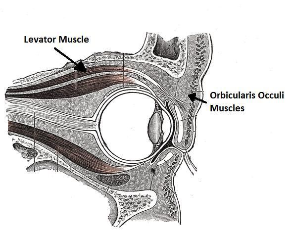
Figure 5: Eye muscle anatomy; highlighting the Orbicularis occuli and
causes it to blink, both
levator muscles
voluntarily and http://en.academic.ru
involuntarily[7]. The
orbicularis occuli is the system of donut-shaped muscles, the innermost of which extends from a
fixed point at the corner of eye, continues through the eyelid, and connects to a fixed point at the
other corner (Figure 4). When these muscles contract, they want to span the shortest possible
distance between the fixed points and due to the geometry of the eyeball the shortest distance is
the closed position. In other words, when you want to close your eyes a message is sent via
electrical impulses from your brain to these orbicularis occuli muscles which, in turn shorten,
causing the upper eyelid to come down upon the lower one. The orbicularis occuli muscles act in
direct opposition to the levator muscle (Figure 5) which pulls the eye back open after a blink has
been completed[7].
Our mechanism imitates these companion muscles using a thin plastic string, the silicone of the
current prosthetics, and a simple coil spring. We intend to form a piece of the silicone material
into the shape of the opening of the eye; the piece will have both an upper and lower lid. We
would then bore a tiny hole into the upper lid and run a thin plastic cord through it. The lids
would then be placed over the acrylic, prosthetic eyeball and fixed at the corners of the eye as
shown in Figure 6. The thin string embedded in the silicone is fixed by an inflexible, stabilizing
strap. The positions of the straps are crucial. They must be placed in such a position so that when
the strings are pulled at the sides the upper eyelid will be forced to come down upon the lower
one. This position will be slightly Figure 6: Embedded cord tension mechanism; viewed from both the front and
the back. Drawn by Blake Marzella
11below the level of the lower eyelid and also located on the same hemisphere as the model
eyeball. The action created by pulling the strings mimics movement of the orbicularis occuli in
the actual eye. The levator muscle action is reproduced by the spring. The spring will be
attached to the upper eyelid at the midpoint between the stabilizing straps. It is positioned here so
that after the strings do work to bring the eye the down the spring force will immediately bring
the upper eyelid back to its initial position, thus completing the blink. Now, our focus turns to
how to get tension on the cord in order to initiate the blink.
Micro Servo Motor
Our first design alternative incorporates a micro servo
motor (Figure 7). A servo is an automatic device that uses
error-sensing feedback to correct its own performance[8]. We
intend to use a miniature servo motor (on the order of
50x50x50mm) to create tension on the aforementioned cords.
The micro servo motor would be located on the side opposite
the eyelids in the cavity of the eyeball. Here, it would be Figure 7: Micro Servo Motor. Model:
GWS Naro+D Micro Digital Servo Motor
fixed by metal supports so that it remained stationary while http://www.robotshop.ca
it worked. The cords would then be attached
to the mechanical arm of the servo, so that
when the arm is spun, the cords are pulled,
and the eye blinks (Figure 8). The ability of
the servo to control and sense its own
position is very important because it allows
us to program the motor to pull the cords Figure 8: Drawing of the embedded cord tension
mechanism powered by a micro servo. Drawn by Michael
just far enough to create a realistic blink and Konrath.
then stop without delay. This feature prevents
any damage to the embedded cord tension mechanism that could be caused by excessive pulling.
Some more advantages of the micro servo include that it has proven to be quick, and strong
relative to its small size. For example, a specific Futaba servo rotates a speed of 60 degrees per
0.19 seconds and generates a torque of 4.1 kg*cm[9]. Another positive feature of the servo motor
12is that it can be easily controlled by a remote, which is essential to our model design because the
presenter will not be able to gain access to the cavity of the eye while presenting. The final, but
maybe the most important benefit of using a micro servo motor to power our mechanism is that
servo motors have a long history and are part of a highly developed market. This makes them
easily obtainable, affordable, and guarantees that there will be plenty of individuals with servo
expertise to help us should we run into problems during assembly or testing. Some concerns
facing this design are noise and bulkiness. Both of these problems have the possibility of causing
the patient discomfort while using our device.
Memory Shape Alloy
Our second design incorporates a memory shape alloy
actuator (Figure 9). The memory shape material is a copper-
based, Nickel-Titanium alloy. The alloy is able to change shape
when an electric current is applied to it. The unique property of
this alloy is that it is able to transform into pre-memorized
shapes when a specific current is applied to it[10]. We would
Figure 9: Shape memory alloy actuator.
fix this actuator in the cavity of the eyeball and then attach the http://www.sparkfun.com
cords to both ends. Thus, when the motor contracts, the
strings are pulled and the eye closes (Figure 10). The benefits of using a motor that incorporates
this memory shape alloy is that it is
silent, small (less than 7cm long),weighs
just over a gram and can be run from a
remote-control. These properties fit into
our project well because we are working in such a
Figure 10: Memory shape alloy actuator drawing.
small place and we also want to minimize any Drawn by Michael Konrath.
discomfort that weight or noise could cause the user. Some problems with this design include
that the memory shape alloy motor has a relatively short life cycle of only about 1,000,000
contractions which would only allow the patient to use it for about a month, before it would need
to be replaced[11]. It also remains to be seen, if the motor will have enough power to pull the
strings far enough to simulate a blink.
13Artificial Muscles (EPAM)
The focus of our third design centers
on a new technology called artificial muscles
or EPAM, which stands for electroactive
polymer artificial muscle. Artificial muscles
consist of a thin layer of dielectric polymer film Figure 11: Basic function of EPAM device
http://www.artificalmuscles.com
between two conductive, compliant electrodes.
When a voltage is applied to these electrodes, the positive and negative charges of the electrodes
attract each other. This causes the polymer to contract in thickness and expand in area because
the polymer as a whole is incompressible. By attaching
materials to direct this motion into the desired axis, an
EPAM actuator is created that can effectively mimic the
muscle movements of living organisms.[12]
Benefits of artificial muscle include that it is fast, Figure 12: Drawing of embedded
EPAM lid Mechanism. Drawn by
completely silent, strong, achieving actuation pressures up to Michael Konrath.
1.9 MPa, and able to contract a large distance relative to its length, having strain values greater
than 30%.[13] Artificial muscles can also be very small, “allowing designs that may achieve the
size and forms of geckos, hummingbirds and cockroaches.” [14] All of these attributes make them
ideal as a power source for our embedded cord tension mechanism. In this case, a small EPAM
actuator would be fixed behind the acrylic artificial eye piece, each end attached to one of the
strings of the embedded cord tension mechanism. When the EPAM actuator would contract, it
would pull both strings and activate the blinking mechanism.
Artificial muscle also lend itself to a unique design of ours called the embedded EPAM
lid. This mechanism would consist of a band of artificial muscle running through the lower edge
of the top silicone eyelid of the prosthesis. This artificial muscle would be fixed at the corners of
the eye so that when it contracted, the shortening of the muscle would force the eyelid
downward. This design borrows heavily from the function of the human orbicularis occuli
muscle as mentioned earlier.
14The largest drawback of EPAM technology comes from its low level of availability.
Currently only one company (Artificial Muscles Inc.) is in charge of commercializing the
product, selling only to other companies or large research groups with large amounts of funding.
EPAM cannot be found in a hobby store and there is no sample kit. Being that so few people
work with this technology nationwide (for example, no one on the UW Madison Campus works
with this technology), it may also prove difficult to get help with our design should we run into
any technical problems.
Design Matrix
Table 1: Design Matrix; the table indicates the weight of each criterion and the scores for each design possibility
Table 1: Design Matrix
Speed Noise Size Power Cost Availability Endurance Total
Weight 20 16 20 20 4 12 8 100
Shape Memory Alloy 3 16 18 4 4 12 2 59
Micro Servo 18 10 13 18 3 12 7 81
Artificial Muscles (EPAM) 16 14 19 16 0 0 7 72
Final Design
Our final design employs the original concept of
the embedded cord tension mechanism. It uses the force
of a cord (fishing line), fixed at the corners of the
prosthetic eye and running through the lower edge of the
silicone eyelid being pulled at both ends, to drive the top
eyelid down onto the lower eyelid. However, after
Figure 13: Picture of final mechanism
working with the materials and the static prosthetic eye
that we used for a base to create our blinking prosthetic eye, our group has made several
considerable adjustments and improvements to the mechanism.
The first major improvement we made was the use of lubrication and other tools to
remove as much friction resisting the blink as possible. The lubrication used to make the lid
slide easily on the acrylic eyepiece is simple vegetable oil. This lubricant does not warp or
15deform the silicone lid and remains on the eyepiece for a considerable amount of time before it
must be reapplied. While working with the silicone area surrounding the acrylic eyepiece, we
found that it puts large amounts of pressure and friction on any object sticking into or through it
(e.g. our fishing line cord). For this reason, our group implanted tiny metal tubes about 1.5mm
in diameter into the silicone area surrounding the eye where the cords from the eyelid would go
through to the back of the mechanism. This, combined with the use of an oil lubricant for the
eyelid, cuts down the friction in the mechanism to the point where our small servo motor has no
problem creating enough torque to activate a blink.
Another large improvement to the original mechanism concerns the how the eyelid
reopens after it is pulled shut. Our original idea was to run a thin spring through the lower edge
of the silicone eyelid and embed the ends of the spring in such a way that the relaxed position of
the spring would keep the eyelid in the open position. We did run into some trouble with this
strategy. If we embedded the two ends of the spring so that the lid looked fully open in its
relaxed position, it created an “overbite” with the lower lid once closed. If we embedded the
spring ends so that this overbite was eliminated, the lid only returned to an open position that
could be described as a “sleepy” eye (it did not go high enough).
To fix this problem, we added a “levator cord” or opening cord to our mechanism. It
should be noted that the spring was left in the lower eyelid because it was observed to help
maintain the eyelids natural curved form. This levator cord is attached to the back of the lid by a
layer of silicone, and runs through the back of the silicone at the top of the eye. When this cord
is pulled, it brings the eyelid to a fully open position. This cord is attached to the servo motor in
such a way that when it is pulled, slack is given to the two ends of the closing cord. When
tension is put on the closing cord, slack is given to the levator cord. In this way neither action,
opening nor closing, opposes the other when creating a blink.
The final improvement or refinement to the original embedded cord tension mechanism
concerns the attachment of the skin of the lid to the silicone area surrounding the eyepiece. It
was originally thought that when the eyelid closes, it stretches the skin over the eye. After
further research it was discovered that the lid actually folds in such a way that it stays taut when
open, but gives slack to the lid when closed. This is how we have attempted to fold our silicone
eyelid.
16As with our original design we have used a servo, the Hitec HS-56, to power our device.
We have programmed this servo to rotate 90° and immediately return to its original position at
the click of a button. When this button is pushed, the servo rotates first in the direction to give
slack to the levator cord and put tension on the closing cords; this closes the eye. As soon as the
eye closes, the servo begins to rotate the opposite direction, putting tension on the levator cord
and giving slack to the closing cords; this reopens the eye.
Testing
Positioning
In order for the embedded cord tension mechanism to work properly, initial tests were
performed to determine the appropriate distance between the servo motor and the blinking eye.
This was accomplished by tying the three strings involved in the mechanism to their respective
places on the micro servo motor arms. The micro servo motor was programmed to provide an
angular displacement of 90 degrees in a clockwise motion when stimulated. As the motor
rotated, we experimented with various lengths of string seeking the correct combination that
would provide the appearance of a natural blink. Due the qualitative nature of observations
gathered when trying to recreate a natural blink, we found the most efficient means of
determining the string length was to use our measurements merely as guidelines and instead to
adjust the lengths of each string upon visual inspection. The measurements used were the
respective displacements of the strings in relation the eyeball during the course of a blink. That
is, during a blink, the upper cord is pulled approximately 1.1 cm toward the center of eye and the
two lower cords are pulled down 1.1 cm.
Reliability
To determine the reliability and durability of our design, we stimulated the prosthetic eye
to blink 50 times and recorded the following data: longest continuous blinks without error,
lubrication requirement, average time to complete one blink, and percentage of complete blinks.
The recorded data is summarized in the following table:
Blinks Longest Lubrication Average Percentage
continuous blinks blink time complete blinks
50 15 1 .33 seconds 84%
Lubrication was originally applied to the eyepiece by spreading less than one mL of vegetable oil
onto the acrylic eye and under the upper lid. Additional lubrication was only added upon the
17visual observation of stuttered eyelid movements as a result of increasing friction. The blink
time was recorded from the instant the mechanism was provided with the stimulus until the
upper eyelid returned to its open position at the end of the blink. Completed blinks were
recorded when the upper eyelid closed to cover the eye entirely and returned fully to the open
and relaxed position.
Assumptions and Inherent Limitations
Much of the testing for this design involved qualitative analysis and visual observation
and adjustments. As such, our methodology does not allow for exact replication of our results or
testing. However, taking into consideration the knowledge that each prosthetic eye must be
individually made and that anaplastology is considered both an art and a science, we feel it is
appropriate and necessary that this mechanism does not provide the ability for exact replication.
That is, since each eyepiece must be custom made it order to create a natural appearance, the
positioning of the blinking mechanism and its components must also be individually adjusted for
each eyepiece in a way which presents an aesthetically pleasing and natural looking blink. This
can only be accomplished through qualitative analysis and thus cannot provide a standard
method of implanting the mechanism within a prosthetic eye.
Future Work
As previously stated, the prototype that we built is meant only to be used as a
presentation device. Moreover, our main goal for this project was to find an adequate and
reliable mechanism to make the prosthetic eye blink. With this goal, our project is by definition a
step toward the real possibility of implanting a blinking orbital prosthesis in an actual patient.
Building a Patient-Ready Model
The first step in constructing a device that would be available for patient use is
minimizing its size. The main components of our device, the eye itself and the servo motor are
relatively small and would be easily housed in the patient’s eye cavity. However, at the present
time the servo motor requires an Arduino USB board for control and an AC adapter for power.
The size of these components is not a problem when the device is being used for presentations,
but it would be unacceptable for patient use. The next step would be to find a motor that can be
controlled without the use of the Arduino board and powered by a battery. During our research,
we were unable to find a motor that would both meet these requirements and produce the torque
18and speed necessary to generate a blink. We believe that with time, technology will develop and
smaller, more suitable motor could replace our micro-servo.
An additional problem with the current servo motor is that it vibrates and creates a
significant amount of heat while working. The vibrations could be a serious problem for a patient
that must wear the prosthesis for an entire day. And the heat would also be hazardous,
considering the sensitivity of the face and its proximity to vital organs (e.g. brain, ears, and
mouth). To solve these problems the type of motor used might need to be changed, but perhaps
vibrations will occur with any motor. In that case, a buffer system might need to be created. The
buffer would hopefully minimize vibrations and cool the motor to prevent harm to the patient.
And as with any electrical device being used on a human patient, any electrical circuit and/or
moving parts must be properly fastened and protected.
Beyond just making the prosthetic eye blink, an effort to synchronize the artificial blink
with the blink of a remaining natural eye must be made. Most, if not all of the realism and
aesthetic appeal gained by wearing a prosthetic eye that can blink, would be lost if blink was not
coordinated with the other eye. This is a completely new problem that can only be solved once a
reliable blinking orbital prosthesis has been made.
Integration & Production
After making the necessary improvements (above) and thorough testing, our client Mr.
Gion would need to approve our device for use at the Medical Arts Prosthetics Clinic. Once
approved, this product would be an available to anyone who has lost an eye. Mr. Gion could
complement his artistic skill with the mechanics of the blink and offer an exciting alternative to
his clients. The prosthetics that incorporated our design would be made on a case by case basis.
Every individual’s situation is unique. Although the fundaments of the design would remain the
same, each device would be slightly different, varying in size, shape, and color.
Summary of Ethical Considerations
Since our goal for this project was to make a model orbital prosthesis for presentation
use, we did not have to take safety into much consideration. Our design would need to undergo
rigorous safety testing before it could be implanted into patients. Safety is the main ethical
concern for our device. As engineers we are responsible for what we create and would be
responsible for putting the patient into dangerous situations and potentially causing them harm if
our device was to have safety flaws. Various organizations such as the US Food and drug
19Administration (FDA), the American Society for Testing and Materials International (ASTM)
and the International Organization for Standardization (ISO) have strict regulations regarding
medical devices implanted into patients.[15] Each individual component as well as our design as
a whole would need to be proven to be safe. We noticed that the servo motor gets quite hot
when used for extended periods of time. This especially would need to be rigorously tested to
show that it could maintain a safe temperature even when used constantly for an entire day.
Until testing is done to meet any organization’s standards, as well as our own, we would not be
comfortable implanting our device into a patient. With proper approval, we would also need to
test our device in clinical trials. Physicians and possibly engineers would need to be present in
case of any complications to ensure patient safety. When our device meets and exceeds all the
safety requirements, our client Mr. Gion, would need to be familiar with all the components so
that when he creates the silicone and acrylic portions of the prosthesis he could properly
implement our mechanics. The patient should also be taught about our device so they can avoid
any improper use.
It is ethically our responsibility to have our device be reliable. If our device failed, it
could put the patient into potentially embarrassing situations. We would not be able to proudly
distribute our design is it were to cause any emotional harm either. Therefore, we would also
like to test the accuracy and durability of our design more thoroughly. Finally, the patient would
have to be informed that they have a choice between our blinking prosthesis, a traditional
prosthesis or even no prosthesis at all.
Appendix A
Consideration of Electromagnets
During our brainstorming process, the idea of using small electromagnets to either attract
or repel a permanent magnet in a prosthetic eyelid to create a blink did arise. The magnets are
small enough, the smallest having a height and width of about .5 inches. They are also
completely silent, which made them a hopeful candidate for one of our designs. Though, when
further research was conducted while attempting to purchase an electromagnet to test, it was
found that these magnets had no magnetic field at only .5 inches away, let alone any power to
attract. The maximum distance of attraction was actually at 1/8 inches. It was also discovered
that these magnets were not made to repel objects. They could be modified to do so, but this
20power to repel would amount to approximately 1/25 of the power of the magnet to attract. For
these reasons, electromagnets were ruled out as a possible design element for the blinking orbital
prosthesis.
References
[1] "Orbital Prosthesis". The Medical Art Prosthetics Clinic. 3-2-10
.
[2] "About Anaplastology". International Anaplastology Association. 3-2-10 .
[3] “Artificial Muscles May Help Patients to Blink.” Medical Device Link. January 25, 2010. Medtech Pulse.
[4] “Plastic Surgery Creates Blinking Device.” The Plastic Surgery Channel. Archives of Facial Plastic
Surgery.
[5] Ahn, J., Choung, H. K., Hwang, S. W., Khwarg, S. I. , Kim, N. J., Lee, M. J., and Sung, M. “Frontalis sling
operation using silicone rod for the correction of ptosis in chronic progressive external ophthalmoplegia.”
British Journal of Opthamology. September 11, 2008. Web.
[6] “Gold Weight and Eyelid Spring.” FPI. April 21, 2009. Facial Paralysis Institute.
[7] Lemke, Bradley, and Mark Lucarelli. Anatomy of the ocular adnexa, orbit, and related facial structures. 2006.
[8] IEEE Industry Applications Magazine March/April 1996, pg 74
[9] Futaba, "Futaba Servos". Hobbico®. 3/2/10 .
[10] Duerig, TW, KN Melton, D Stöckel and CM Wayman. "Engineering Aspects of Shape Memory alloys". ISBN
0-7506-1009-3. London: Butterworth Heinemann, 1990.
[11] "SparkFun Electronics". SparkFun Electronics. 3/1/10
[12] "Artificial Muscle and Biomimetic Robots." SRI International. N.p., n.d. Web. 9 Mar 2010.
.
[13] "Technology." Artificial Muscles Incorporated. N.p., n.d. Web. 9 Mar 2010.
.
[14] Pelrine, Ronald E., Roy D. Kornbluh, and Jose P. Joseph. "Electrostriction of polymer dielectrics with
compliant electrodes as a means of actuation." Sensors and Actuators. A.64 (1998): 77-85. Print.
[15] “The behind-the-scenes road to safe implants.” American Association of Orthopedic Surgeons. April 2010.
Management Planning
21Time Management
Estimated
Task Hours
Brainstorming 25
Research (including opthalmology seminar) 19
Material purchase (including travel) 2
Styrofoam head construction 3
Servo Motor Configuration 9
Blinking mechanism construction 13
Poster/Papers 8
Client Meetings 2.5
Advisor Meetings 7
Total 88.5
Cost Management
Item Price
Arduino USB board $29.95
Momentary push button switch $0.50
1CB86 PC board $1.99
Detector plug $3.29
HS-56HB Servo motor $30.94
Styrofoam display head $13.34
Fishing line $2.84
Total $82.85
Appendix B – Product Design Specifications
Function:
Patients of any gender or age may experience the loss or absence of their eye due to some
type of accident, genetic defect, or disease. Prosthetic eyes are made to help these people have a
greater sense of confidence and positive self-image. Our goal is to create an improved orbital
prosthesis which can restore a truly natural appearance. We intend to accomplish this by
designing a device that enables the prosthetic eye to blink. Our design will focus on developing a
model that portrays this blinking mechanism.
Client requirements:
Costs for the project should be under $500.
22 Create a mechanism to cause the prosthetic eye to blink.
The mechanism should be contained inside of the cavity of the globe of the eye.
Must be damped in order to minimize sound and vibrations.
Must be as aesthetically pleasing.
Blink time must be realistic.
Design requirements:
The model of the orbital prosthesis will only be used in presentation settings, to
demonstrate the blinking mechanism. However, we will still take into consideration the
requirements for a fully functional orbital prosthesis.
1. Physical and Operational Characteristics
a. Performance requirements:
Model: It would be used once a week for 10-20 minutes at a time.
Fully Functional: Must be equipped for continual daily use, 16-18 hours a
day for at least one year.
b. Safety:
Model: Must have proper electrical wiring, in order to prevent electric
shock to the presenter.
Fully Functional: Must be made of easily sanitized materials that are
biocompatible.
c. Accuracy and Reliability:
Model: Must blink when prompted, on every occasion. Must be able to
blink at a rate of 300-400 milliseconds per blink.
Fully Functional: Must be synchronized with the blinking of the other
functional eye.
d. Life in Service:
Model: Reusable; must be usable 300 times a year, ideally for multiple
years.
Fully Functional: Must be operational for daily use for at least a year, with
only minor maintenance.
e. Shelf Life:
Model: The shelf life of or design would be the shelf life of the motor that
we use.
Fully Functional: Skin mimicking gelatin may need to be replaced after
extended use. Batteries might also need to be replaced at regular intervals.
f. Operating Environment:
Model: The device will be used in an open environment and as such will
not be as limited by the size requirements of an eye socket.
Fully Functional: The orbital prosthesis will be used within a patient’s eye
socket. The prosthesis will be limited by the small volume available and
also needs withstand the conditions of the human body.
g. Ergonomics:
Model: The device should be easily operated by a single presenter.
23 Fully Functional: The device must be easily removable, chargeable, and
sterilized.
h. Size:
Model: The maximum size of the prosthesis should be the size of the
human eye socket.
Fully Functional: The fully functional prosthesis should be no bigger than
the model.
i. Weight:
Model: Not an issue. Reasonable weight for one person carrying (3-5 lb.)
Fully Functional: Must be comfortable for patient use.
j. Materials:
Model: Prosthetic eyes now are made out of PMMA, Poly(methyl
methacrylate) and silicone. Our device will use these materials, a light
weight metal and/or plastic for the motor and elastic polymer for the
closing mechanism.
Fully Functional: Any materials that would come in contact with the
patient’s skin will need to be non-allergenic or coated with a material to
prevent any allergic reaction.
k. Aesthetics, Appearance, and Finish:
Model: It should be aesthetically pleasing. The mechanism should be
completely contained within the globe the prosthesis with the exception of
an actuating device (ex. switch or button).
Fully Functional: The goal is to make a more realistic prosthesis, so a
human-like appearance is what the product should display.
2. Production Characteristics
a. Quantity: 1 deliverable.
b. Target Product Cost: Under $500, additional funding will be available if specialized materials
need to be ordered.
3. Miscellaneous
a. Standards and Specifications: We must adhere to the medical device regulations established
by the U.S. government and the World Health Organization. We must also make a device that
satisfies our client’s standards.
b. Customer/Patient related concerns: None for the model. However, the fully functional
prosthesis would need to be small enough to fit comfortably into the patient’s eye socket, quiet,
capable of performing with minimal vibrations, and easy to disinfect regularly.
d. Competition: There have been multiple attempts and possibly successes at a blinking orbital
prosthesis. However, at least here in the Madison area these prosthetics are not available to the
general public for use.
24You can also read