Operation Manual Extended Range Constant Temperature Bath - CANNON Instrument
←
→
Page content transcription
If your browser does not render page correctly, please read the page content below
CT-2000
Extended Range
    Constant
  Temperature
      Bath

Operation
 Manual
Copyright
Copyright © 2021 CANNON Instrument Company®. All rights reserved.

Trademarks
CANNON® and the CANNON® logo are registered trademarks of Cannon Instrument Company®.

Contact
Address:         CANNON Instrument Company®
                 2139 High Tech Road
                 State College PA 16803, USA
Phone:           1-814-353-8000; 1-800-676-6232
Fax:             1-814-353-8007
Website:         www.cannoninstrument.com
Email:
Sales:           sales@cannoninstrument.com
Service:         service@cannoninstrument.com

           Manual P/N 27.9990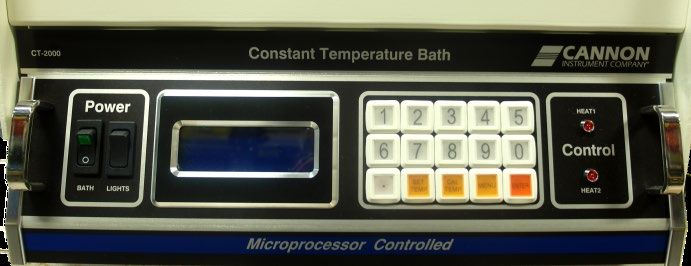
CT-2000 Constant Temperature Bath

Contents
Contents ........................................................................................................................... 1
Introduction/Installation .................................................................................................... 1
  Temperature Selection and Selection ........................................................................................... 1
  Bath Description ...........................................................................................................................2
  ASTM D445 Specifications ............................................................................................................ 3
  Cooling Coil ................................................................................................................................... 3
  Notes/Cautions/Warnings .............................................................................................................4
  Safety Precautions ........................................................................................................................4
     Overheat Thermistor.................................................................................................................4
     RTD Cutoff Detection................................................................................................................4
     Liquid-Level Sensor................................................................................................................... 5
Specifications .................................................................................................................... 7
Unpack & Assemble ........................................................................................................... 8
  Unpack the CT-2000 .....................................................................................................................8
     Damaged Items.........................................................................................................................9
  Assembly Procedure .....................................................................................................................9
  Insert Viscometer Tubes/Thermometers ..................................................................................... 14
     Thermometer Immersion ........................................................................................................ 15
  Filling the Bath ............................................................................................................................ 15
  Drain the Bath ............................................................................................................................. 16
Bath Operation................................................................................................................ 17
  Cold Start .................................................................................................................................... 17
    Bath Lighting .......................................................................................................................... 17
  Warm Start ................................................................................................................................. 17
  Self-Test Sequence ..................................................................................................................... 18
Front Panel Operations .................................................................................................... 21
    ENTER..................................................................................................................................... 21
    Selecting Options/Cancelling Options .....................................................................................22
  Setting Bath Temperature ..........................................................................................................22
    SET TEMP Procedure ..............................................................................................................22
    Data Entry Errors.....................................................................................................................22
    Lower Temperatures ...............................................................................................................22
Calibrating the CT-2000 .................................................................................................... 24
  Procedure ...................................................................................................................................24
  Calibration Theory ......................................................................................................................24

                                                                           CANNON Instrument Company | Contents                                    1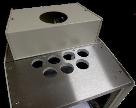
MENU Options ................................................................................................................ 26
 Change to (C/F) ...........................................................................................................................26
   Keypad Sequence:...................................................................................................................26
 Bath Temperature Offsets ..........................................................................................................26
   Keypad Sequence:...................................................................................................................26
   Clear Bins ................................................................................................................................26
   General Bath Offset ................................................................................................................ 27
Communication Options................................................................................................... 28
  Change Port Speed .....................................................................................................................28
    Keypad Sequence....................................................................................................................28
  MODE .........................................................................................................................................28
    Procedure ...............................................................................................................................28
    Keypad Sequence....................................................................................................................28
  Reports .......................................................................................................................................29
    Keypad Sequence....................................................................................................................29
    Full Duplex (point-to-point) Connections ................................................................................ 30
    Half Duplex and Polled (Multi-Drop) Operations ..................................................................... 30
    Commands, Queries & Responses ........................................................................................... 30
    Downloading Firmware ........................................................................................................... 33
Troubleshooting .............................................................................................................. 34
Spare Parts List ............................................................................................................... 36
Warranty ........................................................................................................................ 37
 Products Limited Warranty ......................................................................................................... 37
 Reagent and Chemical Warranty ................................................................................................. 37
 Returning a Product to CANNON ................................................................................................ 37
    Required Information .............................................................................................................. 38
    Hazardous Materials ............................................................................................................... 38
    Shipping Notification .............................................................................................................. 38
Appendix I: Correcting Shaft & Impeller Misalignment ........................................................ 39
  Set Screw Alignment................................................................................................................... 39
  Shaft Run-Out Correction Procedure .......................................................................................... 39
Appendix II: Choosing a Temperature Bath Liquid .............................................................. 41
  IBF Bath Oil ................................................................................................................................. 41
  Silicone Fluids ............................................................................................................................. 41
  Water ..........................................................................................................................................42
  Refined White Oils ......................................................................................................................42

     2         | CT-2000 Operation Manual
List of Figures
Figure 1: CANNON CT-2000 Extended Range Constant Temperature Bath ...................................... 1
Figure 2: CT-2000 Top View of Viscometer Holders ..........................................................................2
Figure 3: CT-2000 Housing ................................................................................................................2
Figure 4: Primary Bath Components .................................................................................................9
Figure 5: Detaching Top Cover Figure 6: Remove Screws from Top Covers....................................9
Figure 7: Remove Top and Rear Top Covers .................................................................................... 10
Figure 8: Checking Support Ring is Seated Properly........................................................................ 10
Figure 9: Placing Rubber Gasket around Rim of Jar ......................................................................... 11
Figure 10: Installing Bath Jar ........................................................................................................... 11
Figure 11: Placing Inner Glass Plate ................................................................................................. 11
Figure 12: Remove Heater Housing ................................................................................................. 12
Figure 13: Install Motor-Stirrer ........................................................................................................ 13
Figure 14: CT-2000 Electrical Connections ...................................................................................... 13
Figure 15: CT-2000 Top View shown without Hole Covers............................................................... 14
Figure 16: Filling the Bath ............................................................................................................... 15
Figure 17: LCD Temperature Setting ............................................................................................... 17
Figure 18: Warm Start Display......................................................................................................... 18
Figure 19: Normal Test Sequence Display ....................................................................................... 19
Figure 20: Self-Test Fail Warning Screen......................................................................................... 19
Figure 21: Press Enter to Attempt Normal Operation...................................................................... 20
Figure 22: RTD Sensor Warning ......................................................................................................20
Figure 23: CT-2000 Front Panel ....................................................................................................... 21
Figure 24: Temperature Graph ........................................................................................................ 23
Figure 25: Clear Bins Warning Message...........................................................................................26
Figure 26: Communication Mode Display .......................................................................................29
Figure 27: Communication Mode Display ........................................................................................29

List of Tables
Table 1: CT-2000 Specifications ....................................................................................................... 7
Table 2: CT-2000 Self-Test .............................................................................................................. 18
Table 3: CT-2000 Commands and Queries ...................................................................................... 31
Table 4: Troubleshooting Causes and Solutions .............................................................................. 34
Table 5: CT-2000 Spare Parts List ................................................................................................... 36
Table 6: Ideal Bath Liquid ................................................................................................................ 41
Table 7: CT-2000 Bath Fluid Options (10 °C to 150 °C)..................................................................... 41

                                                                        CANNON Instrument Company | Contents                                 3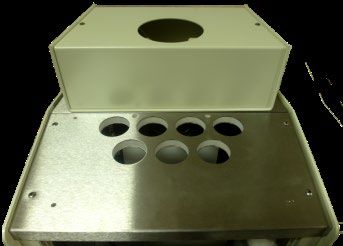
CT-2000 Constant Temperature Bath

iv   Contents | CANNON Instrument Company
CT-2000 Constant Temperature Bath

Introduction/Installation
This manual is intended to provide information on the installation, characteristics and operation of the
CANNON CT-2000 Constant Temperature Bath.
The CANNON CT-2000 Constant Temperature Bath is designed to maintain precise temperatures at a
wide range of settings for accurate viscosity measurements. Because of its temperature stability and
ease of use, it is also suitable for any other application where temperatures must be maintained within
hundredths of one degree Celsius.
The CANNON CT-2000 is designed to maintain temperatures from 10 °C to 150 °C.

               Figure 1: CANNON CT-2000 Extended Range Constant Temperature Bath

Temperature Selection and Selection
The CT-2000 offers convenient keypad entry of temperature settings up to three decimal places over the
entire temperature range of the instrument. The bath temperature will remain stable within one
1/100ths of one degree of the temperature setting.
The CANNON CT-2000 is capable of maintaining temperatures of 10 °C to 100 °C within 0.01 °C and
temperatures of 101 °C to 150 °C within 0.03 °C. (Temperature stability at or below ambient may vary
depending on the quality of the external cooling unit.)

   1      Introduction/Installation | CANNON Instrument Company
Bath Description
The bath chamber is a cylindrical clear vessel 300 mm (12 inches) in diameter and 300 mm (12 inches)
high. A stainless steel baffle coated with white PTFE is located in the center of the bath and provides a
convenient backdrop for viewing viscometers placed within the bath. The top cover contains seven
round holes, 51 mm (two inches) in diameter, for insertion of viscometer holders. Two smaller holes are
provided for thermometers, as shown in Figure 2. Twin fluorescent lamps provide glare-free illumination
of the bath.
Figure 2: CT-2000 Top View of Viscometer Holders
Microprocessor circuitry, functioning in tandem with a pair of heaters and a stainless steel-encased RTD
provides stable and accurate temperature control. A motor-driven stirrer ensures that a uniform
temperature is maintained throughout the bath.
The bath housing is fabricated from heavy aluminum and coated with a corrosion-resistant epoxy. The
top cover consists of three layers: a stainless steel top surface, an insulating layer, and a bottom
stainless steel heat reflector as shown in Figure 3.
Figure 3: CT-2000 Housing
2 | CT-2000 Operation ManualASTM D445 Specifications
The CT-2000 temperature control provides the accuracy required by ASTM D445 for kinematic viscosity
measurements.
Cooling Coil
A built-in cooling coil, when connected to tap water or a cooling system, permits operation to 10 ° C.
CANNON Instrument Company | Introduction/Installation 3Notes/Cautions/Warnings
Please keep this manual easily accessible for necessary information while operating or preparing for
operation.
Notes, caution, and warnings are used in the manual to call an operator’s attention to important details
prior to performing a procedure or step. Read and follow these important instructions. Failure to
observe these instructions may void warranties, compromise operator safety, and/or result in damage
to the instrument.
Notes provide more information about the content that follows.
Cautions alert the operator to conditions that may damage equipment.
Warnings alert the operator to conditions that may cause injury.
It is prohibited to copy or reproduce in part or in whole this manual without authorization by copyright.
If you should find any part in this manual not clear to understand or missing article, contact your local
CANNON dealer or sales representative.
Manufacturer is not liable for any loss or damage directly or indirectly caused by use of the instrument
or its consequences.
This manual pertains directly to the CT-2000 constant temperature bath. For details relating to other
accessories or equipment please refer to the appropriate manufacturer supplied documentation.
Safety Precautions
Always observe cautionary messages, signs and warnings in order to protect yourself as well as prevent
others from physical injury or property damage.
Overheat Thermistor
A thermistor in the bath senses any over-temperature fault condition. If such a condition occurs, all
power is removed from the bath until the operator resets the over-temperature limit circuit.
RTD Cutoff Detection
If the control RTD is disconnected, all power to the bath heaters is cut off.
4 | CT-2000 Operation ManualLiquid-Level Sensor
Bath operation is only possible when it is filled with liquid to a safe operating level. A liquid-level sensor
prevents the control circuit from heating the bath until the safe operating level is attained. The bath
heaters automatically turn off if the bath liquid drops below the minimum safe level.
• Only qualified personnel should operate the CT-2000.
• Place the CT-2000 on a stable surface such as a laboratory table or bench. Do not place instrument
on a cart or stand.
• If any liquids are spilled into the electronic components of the CT- 2000, contact Cannon
Instrument Company immediately.
• Position power cords so they will not be walked on or pinched by items placed on or against them.
Keep all connections as neat as possible.
• Unplug the power cord from the wall outlet if the CT-2000 will not be used for an extended period
of time. Disconnect the power cord by pulling it out by the plug, never pull by the cord.
• Read and understand all operating instructions and safety precautions listed in this manual before
installing or operating the instrument. Any questions regarding instrument operation or
documentation should be referred to Cannon Instrument Company.
• Do not deviate from the installation, operation, or maintenance procedures described in this
manual. Improper use of the CT-2000 may result in a hazardous situation and may void the
manufacturer’s warranty.
• Handle and transport the unit with care. Sudden jolts or impacts may cause damage to
components.
• Never operate the instrument without proper levels of approved bath fluid in bath.
• Observe all warning labels. Never remove warning labels.
• Never operate damaged or leaking equipment.
• Unless procedures specify otherwise, always turn off the unit and disconnect the MAINS cable
from the power source before performing service or maintenance procedures, or before moving
the unit.
• Refer all service and repairs to qualified personnel.
Warning: The bath fluid used with the CT-2000 may be hazardous. Use
proper safety precautions when handling the bath fluid and refer to the
(Material) Safety Data Sheets included with the bath fluid for more detail.
Caution: Do not attempt to service the CT-2000 system by removing panels and
trying to effect repairs. Contact CANNON regarding service and repair needs.
CANNON Instrument Company | Introduction/Installation 5The ~MAINS symbol indicates the connections for the AC power supply. The AC
power input must match the electrical specifications of the instrument.
~MAINS Never operate the equipment with a damaged MAINS AC power cable.
Use only the manufacturer-supplied MAINS AC power cable. This cable must be
inserted into a receptacle with a protective earth ground.
(O) The (O) symbol indicates the OFF position for the electrical switches for your unit.
6 | CT-2000 Operation ManualCT-2000 Constant Temperature Bath
Specifications
Table 1: CT-2000 Specifications
Specifications Details
Model CT-2000 Extended Range Constant Temperature Bath
Methodology ASTM D445, ASTM D446, ISO 3104/3105
Applications Formulated oil analysis, hydraulic oil analysis, additive
analysis, marine fuel testing, base stock analysis, light and
heavy fuel testing, waxes/paraffin, crude oil testing, glycols
Dimensions 43.8 cm × 46.4 cm × 58.4 cm
(W × D × H) (17.25 in × 18.25 in × 23 in)
Weight 51.4 kg (113 lb)
Sample Capacity 7
Temperature Range & 10 °C to 100 °C ± 0.01 °C*
Accuracy 100 °C to 150 °C ± 0.03 °C
*Test temperaturesCT-2000 Constant Temperature Bath
Unpack & Assemble
This section of the manual provides assistance in unpacking and assembling the CT-2000 Constant
Temperature Bath.
Unpack the CT-2000
The CANNON CT-2000 Constant Temperature Bath is shipped in several boxes containing the following
components:
• Bath housing, including the electronics drawer
• Motor and stirrer, including the impeller and mounting plate
• Glass bath jar
• Allen wrench
• Front glass panel pieces (2)
• Seven hole covers
• Jar gasket top and bottom
• Rubber thermometer holder
• Instruction manual
The bath unit housing is shipped completely assembled. However, the glass jar, the glass panels, and the
motor and stirrer must be installed. To install these components, some disassembly of the bath unit
housing is required. The tools required are a utility knife, Phillips screwdriver, and a 1/8" Allen wrench
which is included with the bath. The utility knife and Philips screwdriver must be supplied by the user.
1. Remove all components from the shipping container(s).
2. Remove any and all packing materials (Styrofoam, etc.) from the components.
3. Verify reception of shipped materials by comparing equipment items with packing/parts list(s).
Report missing items to Cannon Instrument Company immediately.
4. Inspect each component for signs of damage. Report any damages to the shipper and to Cannon
Instrument Company immediately.
8 | CT-2000 Operation ManualFigure 4: Primary Bath Components
Damaged Items
Retain all packing materials until the instrument is connected and functioning properly. If any
component(s) must be returned to CANNON, the damaged item(s) should be packaged in the original
shipping container. Refer to the Warranty section of this manual for instructions on returning defective
equipment. Customers outside the United States should contact their local CANNON agent for
procedures on returning products to Cannon Instrument Company.
Assembly Procedure
1. Unpack the bath unit housing and move it to its permanent location on a stable laboratory bench or
table.
2. Remove the eight screws from the stainless steel top covers. Refer to Figure 5 and Figure 6.
Remove all screws
Figure 5: Detaching Top Cover Figure 6: Remove Screws from Top Covers
3. Disconnect all external cabling including probes, heaters, and float switch from the upper rear panel.
4. Remove the front top cover and rear top cover. Carefully remove the rear top cover as the
temperature control probes and heating elements are attached to it, as shown in Figure 7.
CANNON Instrument Company | Unpack & Assemble 9Figure 7: Remove Top and Rear Top Covers
5. Remove the glass jar from its box and packing, using caution as it is heavy.
Caution: The glass jar is heavy. Use caution when lifting/removing jar.
6. Ensure the rubber support ring is properly seated around the bottom of the jar opening in the bath
unit, as shown in Figure 8.
Figure 8: Checking Support Ring is Seated Properly
7. Place the rubber gasket around the top rim of the jar. The rubber may have to be trimmed slightly to
allow the ends of the rubber gasket to meet, with no gap, when placed around the rim. Refer to
Figure 9.
10 | CT-2000 Operation ManualFigure 9: Placing Rubber Gasket around Rim of Jar
8. Remove the large piece of foam packing from the inside of the cabinet. Also remove the small piece
of foam from the float level, located on the upper left corner of the inside of the cabinet.
9. Lower the glass jar into the cabinet so it seats squarely on the rubber support ring. Refer to Figure
10.
Figure 10: Installing Bath Jar
10. Remove the wrapping from around the two glass panels. Place the thinner of the two pieces of glass
in the slot closest to the jar. Refer to Figure 11.
Inner Wall
Figure 11: Placing Inner Glass Plate
CANNON Instrument Company | Unpack & Assemble 1111. Place the wider (tempered) piece of glass in the front slot furthest away from the jar. The middle
slot is left empty to create a vapor barrier.
12. Replace the rear top cover. Align the four holes, then insert and tighten the previously removed
screws.
13. Replace the front top cover. Line up the four holes, then insert and tighten the previously removed
screws.
14. Ensure that the gasket forms a tight seal with the top covers of the bath:
a. Loosen the IEC lock screw securing the AC power cord to the rear panel of the electronics
drawer.
b. Unplug all three cables (AC power, rectangular Cinch connector and round Amp connector) from
the rear of the electronics drawer.
c. Pull out the electronics drawer using the handles installed on the front of the unit. Press down
or pull up on the plastic release bars on either side of the drawer track to release the drawer,
then pull the drawer completely free of the unit and set it aside.
d. When the drawer is removed, locate the four ¼-20 set screws visible at the top of the drawer
opening underneath the bath.
e. Turn the set screws clockwise with the included Allen wrench until the top of the jar forms a tight
seal with the covers. Tighten the set screws uniformly so the jar remains level.
f. Run the AC cord through the rear panel opening.
g. Replace the drawer in the slide tracks and push the drawer back into its opening. Insert the two
power plugs into the rear of the drawer assembly.
15. Remove the motor-stirrer from its box. Remove the two screws on the top heater housing and lift
off the housing. Refer to Figure 12.
Removing two screws
Figure 12: Remove Heater Housing
12 | CT-2000 Operation Manual16. Check the motor-stirrer impeller blades to make sure that the flat sections all lie along the same
plane (see Appendix I: Correcting Shaft & Impeller Misalignment), then insert the motor-stirrer into
the opening provided, as shown in Figure 13.
Insert motor-stirrer
into opening
Figure 13: Install Motor-Stirrer
Caution: Avoid accidental bending of the motor shaft by NOT holding the motor
assembly by the shaft. Use care when inerting the motor shaft and impeller to
prevent damage to delicate components.
Note: Two screws located on either side of the opening serve as the locating pins
for the motor support pad. Do not remove these screws as the holes in the pad fit
loosely over their heads. The motor line cord should point towards the rear of the
bath (offset slightly to the right or left). The motor-stirrer should now lie flat on
the top of the bath.
17. Connect all plugs and probes to the correspondingly labeled sockets at the rear of the CT-2000 bath
unit as shown in Figure 14 and in the following list.
Control Probe
Control Heater
Over-Temp
PreHeat Cable
Level Float Cable
Figure 14: CT-2000 Electrical Connections
CANNON Instrument Company | Unpack & Assemble 13• PREHEAT cable to PREHEAT socket
• CONTROL HEATER cable to CONTROL HEATER socket
• FAN cable to FAN socket
• MOTOR STIRRER cable to MOTOR socket
• CONTROL PROBE cable to CONTROL PROBE socket
• OVER TEMP cable to OVER TEMP socket
• LEVEL FLOAT CABLE to LEVEL FLOAT socket
18. Reattach the top heater housing, ensuring that the heater, motor, and fan cords pass through the
left side opening (as viewed from the rear) and that the control probe, over-temperature probe, and
level switch cords exit from the right side opening (also viewed from the rear). The back lip on the
rear top cover fits into the slot on the top heater housing. Line up the holes, insert screws, and
tighten.
19. Adjust the four leveling feet on the bottom of the bath housing to level the bath jar. This adjustment
must be done prior to filling the bath with fluid.
20. Plug the CT-2000 main power cord at the back of the electronics drawer into an outlet with electrical
specifications matching the label on the rear of the instrument.
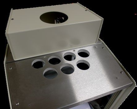
Insert Viscometer Tubes/Thermometers
The top cover of the CT-2000 contains seven apertures, 51 mm (2”) in diameter, for the insertion of
viscometer tube holders. Two additional holes are provided for insertion of thermometers. Refer to
Figure 15.
Figure 15: CT-2000 Top View shown without Hole Covers
If necessary, remove the viscometer tube cover(s) from the top of the bath and carefully place the
viscometer tube(s), with the proper holder attached, into the bath through the aperture(s) in the top
14 | CT-2000 Operation Manualcover. The viscometer tube should be inserted to a depth which ensures that the liquid under test and/
or any timing marks are a minimum of 6 mm (¼") below the top level of the liquid.
Thermometer Immersion
Proper thermometer immersion is critical for viscosity measurements. Even a calibrated thermometer
will read incorrectly if it is not properly immersed in the bath. Total immersion kinematic viscosity
thermometers should be used with the bulb and only the mercury column (if applicable) beneath the
surface of the liquid, but with the emergent stem above the surface at ambient temperatures.
Note: Different thermometers have different immersion requirements. Refer to
the information included with your particular thermometer for specific
requirements.
Filling the Bath
After CT-2000 unit assembly is complete, fill the bath.
Caution: The bath must be placed in its intended final position before adding
bath fluid. Never move the CT-2000 when filled with bath fluid.
Warning: Never use flammable bath liquids.
1. Make sure that the instrument power is OFF and select a bath liquid appropriate to your operating
temperature range. Refer to Appendix II: Choosing a Temperature Bath Liquid.
2. Fill the jar with bath liquid at ambient temperature to a level sufficient to engage the float switch.
This float permits bath operation when the minimum amount of fluid has been added to the bath
jar. Refer to Figure 16.
Figure 16: Filling the Bath
CANNON Instrument Company | Unpack & Assemble 153. Continue to add fluid until the bath liquid level has risen to within approximately 40 mm (1.5") of
the top of the jar.
4. Turn the instrument power ON and incrementally heat the bath to desired control temperature
while monitoring the bath liquid level carefully. The bath level must be 15 mm to 20 mm
(approximately ½" to ¾") from the top of the jar at the control temperature. If it becomes apparent
that this liquid level will not be achieved, return the bath to within 10 °C of ambient, turn the
instrument power OFF, and add or remove liquid as necessary.
5. Repeat step four until you have attained the proper bath liquid level at the desired control
temperature.
Caution: Different bath fluids expand at different rates. Be careful not to overfill
the bath.
Warning: Monitor the bath liquid level closely when operating the CT-2000 at
higher temperatures (100 °C to 150 °C). The bath liquid expands as the
temperature increases. The CT-2000 bath jar is not designed to contain liquid
under pressure. If the bath is overfilled the liquid may overflow and damage
equipment.
Drain the Bath
If it becomes necessary to drain the liquid from the bath, follow the steps outlined in this section.
1. Obtain a suitable container to hold all of the liquid drained from the bath (approximately 20 to 22
liters or 4.5 to 5 gallons), ensuring that the bath liquid is within 10 °C of ambient temperature.
2. Insert a tube into the bath chamber from the top opening and siphon the liquid from the bath into a
container positioned lower than the bath.
Warning: Always use a rubber bulb or similar device to apply suction to a tube
containing bath liquids.
16 | CT-2000 Operation ManualCT-2000 Constant Temperature Bath
Bath Operation
Caution: Do not power on the CT-2000 without completing the installation
requirements. Make sure the MAINS voltage specified on the rear identification
label matches your MAINS voltage.
Note: The CT-2000 stores the “last-used” temperature setting in memory. Upon
power-up, the bath will attempt to adjust to the last known/entered
temperature.
Cold Start
The Cold Start is the normal start-up mode for the CT-2000. During the Cold Start process, the CT-2000
performs several diagnostics (see Self-Test Sequence). At the conclusion of a successful test procedure,
the results are briefly displayed on the LCD screen. The bath heaters are activated and the Bath Unit
begins controlling the temperature according to the most recent temperature entry. The current bath
temperature and the target bath temperature are visible on the liquid crystal display (LCD) as shown in
Figure 17.
Figure 17: LCD Temperature Setting
To Cold Start the CT-2000, toggle the power BATH switch up. The POWER lamp should light when bath
power has been activated. The five LED’s in the lower row of keys will blink on and then off, and the
instrument will emit a short “beep” tone.
Bath Lighting
To activate the Bath Unit fluorescent lights, toggle the LIGHTS switch up. The switch lamp indicator lights
up when power is supplied to the fluorescent lights.
Warm Start
The Warm Start is the abnormal start-up mode for the bath and it occurs only if the power was
previously off for a period of less than about two seconds, or if a fault was detected in the
microprocessor during the Self-Test Sequence. If the CT-2000 Process Function Monitor senses a
momentary or ongoing failure in the system hardware and/or software, the heating elements are shut
down and the system is reactivated in Warm Start mode. The keypad lights flash in a repeating pattern
and the heater power is disabled (heating LED will not light).
The display will appear as shown in Figure 18.
CANNON Instrument Company | Bath Operation 17Figure 18: Warm Start Display
If this condition occurs:
1. Turn the BATH power switch off.
2. After waiting at least five seconds, turn the BATH power switch to the ON position and wait for the
display to indicate either a warm or cold start again.
3. If the bath comes up in a Cold Start condition and starts its normal self-test sequence, it is likely that
a momentary power interruption caused the Warm Start condition and no further action is required.
4. If the bath continues to enter the Warm Start condition, consult CANNON for further assistance.
Self-Test Sequence
The CT-2000 start-up includes a self-test procedure encompassing key components of the system. These
tests, which are displayed on the LCD during start-up, are described in Table 2.
Table 2: CT-2000 Self-Test
Test Test Purpose
Verifies function of the liquid crystal display (LCD) screen. User may
Display
visually check for bad segments on the display.
32K Ram Verifies normal operation of CT-2000 system memory.
Pulse Width Modulator Verifies function of the PWM.
A/D Calibrates analog-digital converter and verifies function and consistency.
Voltage Levels Verifies power supply voltage levels (positive and negative).
18 | CT-2000 Operation ManualFigure 19 illustrates the LCD sequence for a normal self-test:
Figure 19: Normal Test Sequence Display
If the self-test sequence is accomplished successfully, the CT-2000 commences normal operations.
If any component of the self-test fails, a FAILED message will appear on the LCD, accompanied by an
audible warning tone as shown in Figure 20.
Figure 20: Self-Test Fail Warning Screen
CANNON Instrument Company | Bath Operation 19The ENTER key will flash in a repeating pattern and the heating LED will not light (see section Warm
Start). In the event of a FAILED test, turn off the CT-2000 power for at least five seconds and then restart
the unit.
It may be possible to resume normal operation of the CT-2000 following a failed self-test by pressing the
ENTER key. If ENTER is pressed, the “Attempting Normal Operation” LCD message appears as shown
in Figure 21.
Figure 21: Press Enter to Attempt Normal Operation
Caution: A failed self-test may result in flawed operation and damage to the CT-
2000. If the CT-2000 repeatedly fails the self-test sequene, call CANNON to
arrange for a service call for the unit.
Following the self-test, the CT-2000 proceeds with its normal display condition provided that the RTD
temperature sensor is connected properly. If the RTD sensor is unplugged at any time, the LCD displays a
warning that it is necessary to reconnect the RTD before proceeding with normal bath operations. Refer
to Figure 22.
Figure 22: RTD Sensor Warning
20 | CT-2000 Operation ManualCT-2000 Constant Temperature Bath
Front Panel Operations
Following a successful Cold Start (refer to Bath Operation if needed), the CT-2000 is ready for
instructions from the user.
Note: Check bath fluid levels before commencing with use of the CT-2000.
The front panel of the CT-2000 provides a Liquid Crystal Display (LCD) screen and a simple keypad
interface as shown in Figure 23.
Figure 23: CT-2000 Front Panel
The keypad on the front panel of the CT-2000 consists of fifteen keys:
• White buttons - numbers 0 through 9
• A white button - decimal point (.) key
• A yellow button - SET TEMP (set temperature) key
• A yellow button - CAL TEMP (calibrate temperature) key
• A yellow button - MENU key
• An orange button - ENTER key
The keys on the bottom row (non-numerical yellow and orange keys) illuminate to assist the operator in
selecting key entry options.
Press the appropriate keypad choice(s) firmly to make your selections. The CT-2000 signals reception of
each keypad command with a short, high-pitched beep sound. A longer beep indicates a data entry error
(unacceptable input), such as a temperature value outside the range of the unit.
ENTER
The ENTER button is the most-used feature on the CT-2000 keypad. Each menu choice and numeric
input must be confirmed by pressing the ENTER button.
CANNON Instrument Company | Front Panel Operations 21Selecting Options/Cancelling Options
Press the appropriate keypad button once to access that option (SET TEMP, CAL TEMP or MENU). If
you make a data entry error and wish to cancel your input sequence, simply press the original keypad
option button again to clear data.
Note: If the keypad does not receive user input for five minutes after a primary
option is selected, the instrument returns to the LCD temperature display screen
without saving any changes.
These three buttons are the only options available when the Cold Start routine is begun—SET TEMP,
CAL TEMP and MENU:
• SET TEMP allows user to enter the desired bath temperature setting. See details below.
• CAL TEMP allows user to recalibrate the temperature sensing mechanism. See section Calibrating
the CT-2000.
• MENU allows user to change temperature scale (°F or °C), reset calibration offsets and change
other system settings (See section MENU Options).
Setting Bath Temperature
SET TEMP Procedure
1. To set the bath temperature, choose SET TEMP from the keypad after a successful Cold Start.
2. The LCD displays a message requesting input of the new target temperature. Use the numerical keys
to enter the new temperature. Enter positive numbers from 10 °C to 150 °C (50 °F to 302 °F) with
up to three decimal places.
3. Press the ENTER key to save your data. The bath now attempts to equilibrate at the new
temperature.
The temperature may be reset at any time.
Data Entry Errors
If data is entered incorrectly while setting the temperature, press the SET TEMP key again to exit the
data entry screen. Then repeat the SET TEMP procedure.
Lower Temperatures
If the desired temperature setting is slightly above or below ambient, coolant must be circulated
through the cooling coil. Input/output connections for the coil are located on the upper portion of the
rear panel.
Coolant temperature must be lower than the desired CT-2000 control temperature.
Caution: Extreme temperatures or variability in the temperature of the coolant
liquid may adversely affect the CT-2000 temperature control.
22 | CT-2000 Operation ManualNote: If a temperature is entered that is outside the operational temperature
range of the CT-2000, a RANGE ERROR message appears on the LCD screen. To
correct this error, press ENTER and follow the prompts to enter correct data.
When the CT-2000 is controlling temperature within 1/10th of a degree, the LCD displays a temperature
graph in 5/100th degree increments at the bottom of the LCD screen. A small “tick” mark above the
graph provides a visual cue to the exact temperature of the bath relative to the requested temperature.
Refer to Figure 24.
“tick” mark
Figure 24: Temperature Graph
CANNON Instrument Company | Front Panel Operations 23CT-2000 Constant Temperature Bath
Calibrating the CT-2000
The CT-2000 has the ability to be calibrated to a temperature reference standard for any desired
temperature, Celsius or Fahrenheit. The controls for entering the target (desired) temperature and the
calibration at this temperature are convenient and largely intuitive. The instrument stores calibration
corrections for every temperature integer.
Procedure
Use the CAL TEMP keypad option to calibrate the CT-2000 to your ASTM thermometer for a given
temperature.
Note: Before calibrating the CT-2000, make sure the bath has stabilized at the
desired temperature.
1. Set the CT-2000 to the desired test temperature.
2. When the CT-2000 indicates that the instrument is controlling at the desired temperature, place the
thermometer in the bath and wait for the temperature reading to stabilize (at least 10 minutes).
3. Press the CAL TEMP key and enter the thermometer reading up to three decimal places, subject to
the following parameters:
a. A decimal point may be included as an entry.
b. The entered temperature must be within the operational temperature range of the bath. If not,
a CALIBRATION ERROR is displayed on the LCD screen.
c. The entered actual temperature must not cause a correction in temperature greater than ± 2.5
°C.
Note: If an error is made when entering the temperature, press the CAL TEMP
button again to cancel the operation, exit the calibration screen and reurn to
normal CT-2000 operation.
4. When data entry is complete, press ENTER to store the calibration data.
5. A new calibration constant has been stored for that test temperature.
6. You may now recalibrate for any test temperature at any time.
Calibration Theory
The CT-2000 stores user calibration information in a “bin” corresponding to every temperature integer.
This calibration adjustment value for the bin is effective at all temperature ranges within 0.5 degrees of
the temperature integer.
24 | CT-2000 Operation ManualThe CT-2000 combines user calibration input with readings obtained by the temperature probe and data
from the general bath offset, a protected menu option, which is preset at the factory by Cannon
Instrument Company (see the MENU Options section for more information).
CANNON Instrument Company | Calibrating the CT-2000 25CT-2000 Constant Temperature Bath
MENU Options
The MENU selection from the CT-2000 keypad permits the user to access three functions:
• Change to (C/F): Changes screen display to alternate temperature scale
• Bath Temperature Offsets: Globally adjusts calibration data
• COM Setup: Sets computer communication options
Change to (C/F)
The Change to (Celsius or Fahrenheit) option is essentially a toggle between two temperature scales. If
the instrument is currently displaying numeric data in degrees Celsius, selecting this option changes the
scale to Fahrenheit, and vice versa.
To switch from one unit of measure to another, press the MENU key, press 1 and press ENTER.
Keypad Sequence:
MENU > 1 > ENTER
Bath Temperature Offsets
To select a Bath Temperature Offset function, first press the MENU key, then press 2, and press
ENTER.
Keypad Sequence:
MENU > 2 > ENTER
The Bath Temperature Offset option, when selected, displays two sub-menus:
• Clear Bins: Clears all user-input calibration data for individual bins
• Set General Bath Offset: Allows global calibration adjustment by CANNON.
Clear Bins
In rare instances, it may be desirable to clear all temperature calibrations and recalibrate each offset. To
accomplish this function, select Clear Bins, then press 1. The LCD will display a warning message as
shown in Figure 25.
Figure 25: Clear Bins Warning Message
26 | CT-2000 Operation ManualTo erase user calibration data for all integer bins, press the ENTER key. To exit the Clear Bins screen
without altering user calibration data, press the MENU key.
Caution: Once the offset values are cleared they cannot be restored. The
instrument may require recalibration for all offsets to produce reliable data.
General Bath Offset
The General Bath Offset is a protected function of the CT-2000. This option is a global adjustment which
is made at the factory by CANNON. In rare instances when this setting may need to be altered, the
adjustment should be made in consultation with an authorized CANNON representative.
CANNON Instrument Company | MENU Options 27CT-2000 Constant Temperature Bath Communication Options Several communication options between the CT-2000 and your computer may be configured from the MENU keypad option. Change Port Speed The Change Port Speed option provides a speed setting for data transfer between the CT-2000 and a computer via the RS-232C connection. Select the baud rate (the default for most software is 9600) in bps (bits per second) from one of the following options: 1. 1200 2. 2400 3. 8600 4. 19.2k 5. 38.4k Keypad Sequence MENU > 3 > ENTER > 1 > ENTER > Input speed choice (1 – 5) > ENTER MODE The MODE keypad option permits RS-232C or RS-485 communication options. The CT-2000 is equipped with a full-duplex RS-232C point-to-point interface as well as a half-duplex RS- 485 network interface. Commands and Queries may be sent to the CT-2000 via either interface. Responses and Reports may be received by the master controlling computer. This interface is configured as 8 data bits with no parity and one stop bit. The mode of operation, polled (multi-drop) or point-to-point, can only be configured via the front panel menu. Procedure To select the MODE option, press 2 from the COM Setup menu. Keypad Sequence MENU > 3 > ENTER > 2 > ENTER If the CT-2000 was previously configured to operate in a polled (RS-485) environment, the Communication Mode message appears on the LCD as shown in Figure 26. 28 | CT-2000 Operation Manual
Figure 26: Communication Mode Display
The last line on the LCD indicates that timed reports are disabled and the present mode is polled.
In this example, the keypad sequence to press in order to operate in a point-to-point (RS-232)
environment with or without timed interval reports is: 2 > ENTER
If the CT-2000 is configured to operate in a point-to-point (RS-232) environment, the Communication
Mode message appears on the LCD when the RS-232 option is enabled, as shown in Figure 27.

                                Figure 27: Communication Mode Display
The last line on the LCD (3. Config Reports) indicates that timed reports may be utilized and the present
mode is point-to-point (2). In this example, the keypad sequence to reset the bath to a polled
environment is: 1 > ENTER

Reports
The Reports option is accessed from the MODE sub-menu and is only enabled when the Point-to-Point
mode is selected.

Keypad Sequence
(from initial LCD temperature display):
MENU > 3 > ENTER > 2 > ENTER > 3 > ENTER
The report is a serial dump of information on the operation of the CT- 2000 and includes:

 •   Instrument address

 •   Unit of temperature measurement (C/F)

 •   A time reference

 •   Target bath temperature

 •   Actual bath temperature (as measured by the bath RTD)

                                   CANNON Instrument Company | Communication Options                 29
The frequency of temperature sampling (in seconds) for the report can then be selected from the
options on the LCD screen. The report parameters range from a report each second (keypad selection 2
> ENTER) to a report every two minutes (keypad selection 8 > ENTER).
Note: This option can be turned off (selection 1) if there is no computer
connected via the serial line.
The serial connection can only provide time interval reports of the actual and desired bath temperatures
if the CT-2000 is configured in the point- to-point mode of operation. Otherwise, the REPORTS
DISABLED message appears on the LCD and report configuration options cannot be accessed until the
point-to-point mode is resumed.
Full Duplex (point-to-point) Connections
The RS-232 interface is furnished for a direct connection between the CT-2000 and one computer. A DB-
25 connector on the rear panel of the CT-2000 is configured as Data Communication Equipment (DCE).
This configuration permits a direct connection (straight through cable--pins 1- 8, 20).
An existing computer’s DB-9 connector may be used with a DB-25 adaptor cable (DB-25 male connector
to DB-9 female connector).
Half Duplex and Polled (Multi-Drop) Operations
The RS-485 interface is provided to permit network connections from one computer to a multiple
number of instruments. A three-wire (with feed-through) screw terminal connector is located on the CT-
2000 rear panel. A three-conductor cable (two wire-shielded preferred) can be connected to the
instrument via this terminal. The computer must have an RS-232 to RS-485 adaptor plugged into the
computer serial port. With the 3-wire connection in place, the network is capable of supporting up to 16
instruments at cable distances up to a combined total of 4000 feet.
With three or more occupants or long distances, termination resistors may be added to enhance the
performance of network operations. Contact CANNON service for further assistance on more extensive
network configurations.
Commands, Queries & Responses
The protocol for the serial interface includes commands and queries sent by the master controlling
computer, and replies/responses sent by the CT-2000. The CT-2000 may also issue timed interval reports
automatically if configured to do so in the point-to-point mode (see Reports). In the polled (multi-drop)
mode, specific reports are only issued in response to a specific query.
All Commands or Queries must be preceded by the forward slash (/) and the selected address (0-9 or A-
F). Commands are identified with the letter C and Queries are identified with the letter Q; these
identifiers follow the address and precede the command or query information. All Commands or
Queries must end with a carriage return (ENTER).
For examples of CT-2000 command and query language, consult Table 3 on the following pages.
30 | CT-2000 Operation ManualTable 3: CT-2000 Commands and Queries
Possible
Command
Argument Action Description
Type ($$)
(&..&)
Calibrate the 16 bit A to D converter. When complete, the response
is AD_NO if the calibration failed or AD_YES if calibration is
AD None successful. If the command is not recognizable, ERROR is displayed.
For example, if this command is sent to a CT-2000 with an address of
5: /5CAD; then the response may be: -5CADYES
Run a complete self-test like the one run at power up. A response
immediately indicating receipt of command RT_YES, or the
RT None command is unrecognizable and ERROR is displayed.
For example, if this command is sent to a CT-2000 with an address of
6: /6CRT; then the response may be: -6CRTYES
Display all temperatures in °C on LCD and in all reports. This
command places the bath in Celsius mode for all temperature
references. An immediate response of command DCYES is returned,
DC None
or if command is unrecognizable then ERROR is displayed.
For example, if this command is sent to a CT-2000 with an address of
1: /1CDC; the response may be: -1CDCYES
Display all temperatures in °F on LCD and in all reports. This
command places the bath in Fahrenheit mode for all temperature
references. An immediate response of command DCYES is returned,
DF None
or if command is unrecognizable then ERROR is displayed.
For example, if this command is sent to a CT-2000 with an address of
2: /2CDF; then the response may be: -2CDFYES
Set the reporting interval to the value of half-seconds as defined by
the three character argument &&& in hexadecimal. Only arguments
from 000 to FFF are accepted where 000 turns all reports off and any
other numbers permit reports to be issued on any half-second
interval from 0.5 seconds up to 2,047.5 seconds, but only if the CT-
2000 is in point-to-point mode of operation. If the command is
SR &&&
accepted, instrument returns an SRYES response and the new report
interval takes effect. If an invalid hex is given, a response of SR_NO is
displayed and anything else results in an ERROR.
For example, if this command requesting reports every one second
interval is sent to a CT-2000 with an address of 3: /3CSR002; the
response may be: -3CSRYES
Set the desired target temperature of the bath as defined by the
ST +&&&.&&& argument +&&&.&&&, in °C or °F as previously established. Only
fixed point numbers are accepted and must be within the bath’s
CANNON Instrument Company | Communication Options 31You can also read