ICE Cubes - ICE Cubes Service
←
→
Page content transcription
If your browser does not render page correctly, please read the page content below
Reference :   ICU-SA-RQ-004
                                                                  Version :               1.3.0
                                                                  Date      :      29-Aug-2018

                ICE Cubes Facility to Experiment Cube IRD

                             ICE Cubes

Title       :   ICE Cubes Facility to Experiment Cube IRD

Abstract    :   This document provides a comprehensive interface definition between
                the ICE Cubes Facility (ICF) and the Experiment Cube to the ICE
                Cubes service customer (i.e. Experiment Cube development
                responsible).

                This IRD is to be complemented by the guidelines ICU-SA-TN-011
                [RD1] and the ICD template ICU-SA-ICD-002 [RD2].

                All three documents are updated at regular intervals. Before
                proceeding, the reader shall ensure to be in possession of the latest
                versions by checking on our website:
                http://icecubesservice.com/

                         International Commercial
                            Experiments Service

           Copyright by Space Applications Services – All Rights Reserved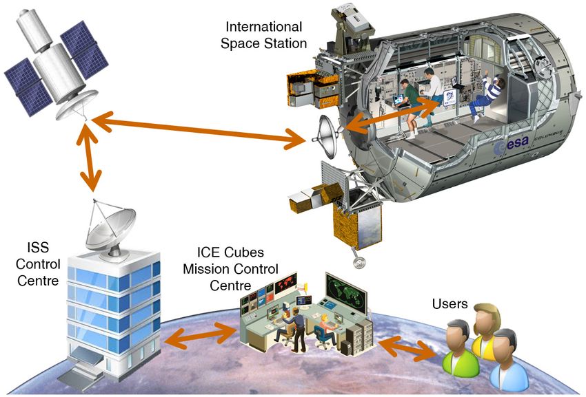
Reference :   ICU-SA-RQ-004
                                                                              Version :               1.3.0
                                                                              Date      :      29-Aug-2018
                                                                              Page      :                 2

                               ICE Cubes Facility to Experiment Cube IRD

                                    DOCUMENT APPROVAL SHEET

Responsibility   Name and Position        Company                          Signature and Date

Prepared by:     ICE Cubes Team           Space Applications Services

Checked by:      T. Peignier              Space Applications Services
                 System Engineer

PA Checked by:   L. Tazi                  Space Applications Services
                 PA&S Engineer

Approved by:     M. Ricci                 Space Applications Services
                 Project Manager

                                  Space Applications Services NV/SA

                                     www.spaceapplications.com

                       Leuvensesteenweg 325           1932 Sint-Stevens-Woluwe

                      (Brussels Area), Belgium        Tel: +32-(0)2-721.54.84

                                   This document is the property of

                                 Space Applications Services NV/SA.

                                          All rights reserved.

                      Copyright by Space Applications Services – All Rights Reserved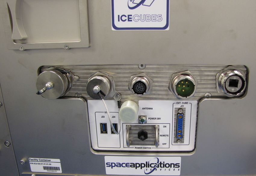
Reference :       ICU-SA-RQ-004
                                                                                Version :                   1.3.0
                                                                                Date      :          29-Aug-2018
                                                                                Page      :                     3

                             ICE Cubes Facility to Experiment Cube IRD

                                    DOCUMENT CHANGE RECORD

Version   Date          Author                Changed                 Reason for Change / RID No
                                              Sections / Pages

1.0.0     29-Jul-2016   ICE Cubes Team                                Initial release

1.1.3     30-Jan-2017   ICE Cubes Team        All                     Draft release for PDR

1.2.0     16-Mar-2018   ICE Cubes Team        §1.3, §3.4.1,           Update of RDs; Electrical interface
                                              §3.5.1, §3.6.1,         update; Addition of clarifications about
                                              §3.6.3, §3.6.5,         communications between UHBs and
                                              §3.6.7, §3.8.1,         Experiment Cubes, and about antivirus;
                                              §3.8.10, Appendix       Addition of §3.6.7; Deletion of §4.2.3.7 to
                                              A, Appendix C,          §4.2.3.9; Addition of Appendix A and
                                              Appendix D              Appendix D; Update of Appendix C;
                                                                      Editorial corrections throughout the
                                                                      document

1.2.1     20-Apr-2018   ICE Cubes Team        §3.4.1, §3.5.1.3        Figure 13 minor update; Addition of
                                                                      capacitive coupling requirement

1.3.0     29-Aug-2018   ICE Cubes Team        §1.1, §1.2, §1.3,       Deletion of AD1; Addition/update of RDs;
                                              §2.1, §2.2, §2.3,       Update of figures; Addition of §2.3.1,
                                              §2.4, §3.1.1,           §2.3.2, §2.4.1, §2.4.2; Addition of
                                              §3.1.3, §3.1.7,         clarifications (e.g. notes); Update of
                                              §3.1.8, §3.2.1,         requirements; Deletion of §3.6.3; Addition
                                              §3.2.2, §3.2.3,         of §3.8.7 and §3.9.3; Update of Appendix
                                              §3.3.2, §3.3.4,         A and Appendix C
                                              §3.5.2, §3.5.3,
                                                                      All changes above are indicated by black
                                              §3.6.3, §3.6.4,
                                                                      bars in the page margins)
                                              §3.8.3, §3.8.7,
                                              §3.8.8, §3.9.2,         Editorial corrections (not indicated by
                                              §3.9.3, §4.2.1,         black bars) throughout the document
                                              Appendix A,
                                              Appendix C

                        Copyright by Space Applications Services – All Rights Reserved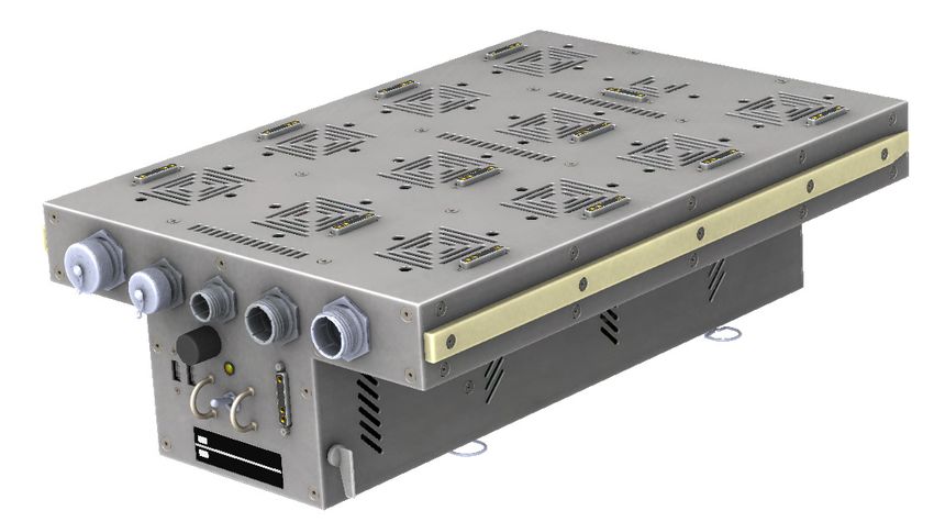
Reference :             ICU-SA-RQ-004
                                                                                                      Version :                         1.3.0
                                                                                                      Date      :                29-Aug-2018
                                                                                                      Page      :                           4

                                        ICE Cubes Facility to Experiment Cube IRD

                                                   Table of Contents
1   Introduction ................................................................................................................................. 9
    1.1         Purpose and Scope .......................................................................................................... 9
    1.2         Applicable Documents ...................................................................................................... 9
    1.3         Reference Documents ...................................................................................................... 9
    1.4         Acronyms ........................................................................................................................ 10
2   ICE Cubes Flight Segment Overview ...................................................................................... 13
    2.1         The ICE Cubes Facility (ICF) ......................................................................................... 13
    2.2         The Framework .............................................................................................................. 14
    2.3         “Internal” Experiment Cubes .......................................................................................... 15
                2.3.1       Experiment Cube Locations on the ICF ............................................................ 16
                2.3.2       ICF Sliding Door ................................................................................................ 17
    2.4         “External” Experiment Cubes and Other Payloads ........................................................ 18
                2.4.1       ICF J21 Connector (DB13W3S) ........................................................................ 20
                2.4.2       ICF J22 Connector (RJFTV71N) ....................................................................... 20
    2.5         Thermal Cooling ............................................................................................................. 20
3   Experiment Cube Flight Interface Requirements ................................................................... 22
    3.1         Mechanical Requirements .............................................................................................. 22
                3.1.1       Experiment Cube Connector ............................................................................. 22
                3.1.2       Outer Surfaces................................................................................................... 23
                3.1.3       Fins, Vents and Fans ......................................................................................... 23
                3.1.4       Standard Form Factors ...................................................................................... 24
                3.1.5       Dimensions & Tolerances .................................................................................. 24
                3.1.6       Sharp Edges ...................................................................................................... 25
                3.1.7       Audible Noise..................................................................................................... 25
                            3.1.7.1         Continuous Noise Limits .................................................................. 25
                            3.1.7.2         Intermittent Noise Limits .................................................................. 25
                            3.1.7.3         Audible Noise Limits Verification ..................................................... 25
                3.1.8       Microgravity Disturbances ................................................................................. 25
    3.2         Structural and Environmental Interface Requirements .................................................. 26
                3.2.1       Environmental Conditions .................................................................................. 26
                            3.2.1.1         Temperature, Pressure and Humidity Conditions ........................... 26
                            3.2.1.2         Depressurization/Re-Pressurization Conditions .............................. 26
                            3.2.1.3         Thermal Environment inside the ICE Cubes Facility ....................... 27
                3.2.2       Launch & Landing Loads ................................................................................... 27
                3.2.3       Random Vibration Loads ................................................................................... 27

                                Copyright by Space Applications Services – All Rights Reserved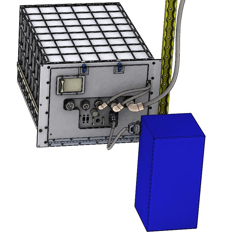
Reference :             ICU-SA-RQ-004
                                                                                            Version :                         1.3.0
                                                                                            Date      :                29-Aug-2018
                                                                                            Page      :                           5

                             ICE Cubes Facility to Experiment Cube IRD

      3.2.4      Shock Loads ...................................................................................................... 27
3.3   Thermal Requirements ................................................................................................... 28
      3.3.1      Temperature Control ......................................................................................... 28
      3.3.2      Touch Temperature ........................................................................................... 28
      3.3.3      Thermal Sensor ................................................................................................. 28
      3.3.4      Condensation Prevention .................................................................................. 28
3.4   Electrical Interface Requirements .................................................................................. 28
      3.4.1      DB13W3 Connector Proprietary Wiring ............................................................. 28
      3.4.2      Power ................................................................................................................. 29
      3.4.3      Unexpected Power Loss .................................................................................... 29
3.5   Electrical and Electromagnetic Compatibility (EMC) Requirements .............................. 30
      3.5.1      Grounding, Bonding & Isolation ......................................................................... 30
                 3.5.1.1          Grounding (i.e. Ground Return) ....................................................... 30
                 3.5.1.2          Bonding (i.e. Chassis Ground) ........................................................ 30
                 3.5.1.3          Isolation ........................................................................................... 30
      3.5.2      Electromagnetic Interference (EMI) ................................................................... 31
                 3.5.2.1          E-Field Radiated Emissions ............................................................ 31
                 3.5.2.2          B-Field Radiated Emissions ............................................................ 31
                 3.5.2.3          Conducted Emissions ...................................................................... 32
                 3.5.2.4          Radiated Susceptibility / Immunity................................................... 32
                 3.5.2.5          Conducted Susceptibility / Immunity................................................ 33
                 3.5.2.6          Electromagnetic Interferences Verification ...................................... 34
      3.5.3      Electrostatic Discharge (ESD) Susceptibility / Immunity ................................... 34
      3.5.4      DC Magnetic Fields ........................................................................................... 34
3.6   Data & Communication Interface Requirements ............................................................ 35
      3.6.1      Experiment Cube IP Communication ................................................................ 35
      3.6.2      Experiment Cubes Data Synchronization Service............................................. 36
      3.6.3      Experiment Cube Download of Data ................................................................. 36
      3.6.4      Experiment Cube Software Security ................................................................. 36
      3.6.5      Gigabit Ethernet Interface.................................................................................. 36
      3.6.6      Intentional Transmitters and Receivers ............................................................. 37
3.7   Materials Requirements ................................................................................................. 37
      3.7.1      Declared Materials List (DML) ........................................................................... 37
      3.7.2      Forbidden Materials and Components .............................................................. 37
      3.7.3      Surface Treatments & Protective Coatings ....................................................... 37
      3.7.4      Flammability....................................................................................................... 37

                     Copyright by Space Applications Services – All Rights Reserved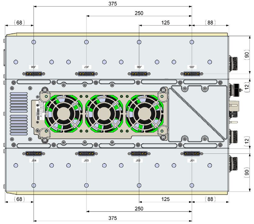
Reference :             ICU-SA-RQ-004
                                                                                                   Version :                         1.3.0
                                                                                                   Date      :                29-Aug-2018
                                                                                                   Page      :                           6

                                    ICE Cubes Facility to Experiment Cube IRD

             3.7.5      Offgassing.......................................................................................................... 37
             3.7.6      Fasteners Locking ............................................................................................. 38
    3.8      Safety Requirements ...................................................................................................... 38
             3.8.1      Collection of Safety-Related Data ..................................................................... 38
             3.8.2      Non-Conformity with Requirements .................................................................. 38
             3.8.3      Containment ...................................................................................................... 38
             3.8.4      Volatile Organic Compound............................................................................... 38
             3.8.5      Glass or Frangible Materials Release ............................................................... 38
             3.8.6      Lasers ................................................................................................................ 38
             3.8.7      Light Sources ..................................................................................................... 38
             3.8.8      Batteries and (Super-) Capacitors ..................................................................... 39
             3.8.9      Pyrotechnics ...................................................................................................... 39
             3.8.10 Smoke & Fire Detection ..................................................................................... 39
             3.8.11 Flight Readiness Certification ............................................................................ 39
    3.9      Human Factor Interface Requirements .......................................................................... 39
             3.9.1      Astronaut Interaction ......................................................................................... 39
             3.9.2      Identification & Marking ..................................................................................... 39
             3.9.3      Crew Safety ....................................................................................................... 39
    3.10     Reliability Requirements ................................................................................................. 40
4   Experiment Cube Ground Interface Requirements ............................................................... 41
    4.1      Hardware Interface ......................................................................................................... 41
    4.2      Software Interface .......................................................................................................... 41
             4.2.1      UHB to ICMCC Interface Overview ................................................................... 41
             4.2.2      Mandatory Software Interface Requirements .................................................... 42
                        4.2.2.1          Software Host .................................................................................. 42
                        4.2.2.2          Connection to the ICMCC ................................................................ 42
                        4.2.2.3          Two-Factor Authentication ............................................................... 42
                        4.2.2.4          Security, Split Tunnelling ................................................................. 42
                        4.2.2.5          System Time Synchronisation ......................................................... 42
             4.2.3      Optional Software Interface Requirements ....................................................... 43
                        4.2.3.1          Data Synchronization Service Downlink .......................................... 43
                        4.2.3.2          Data Synchronization Service Uplink .............................................. 43
                        4.2.3.3          Private IP Address ........................................................................... 43
                        4.2.3.4          Direct TCP and UDP Communication ............................................. 43
                        4.2.3.5          TCP and UDP Protocol .................................................................... 43
                        4.2.3.6          UDP Connection .............................................................................. 43

                             Copyright by Space Applications Services – All Rights Reserved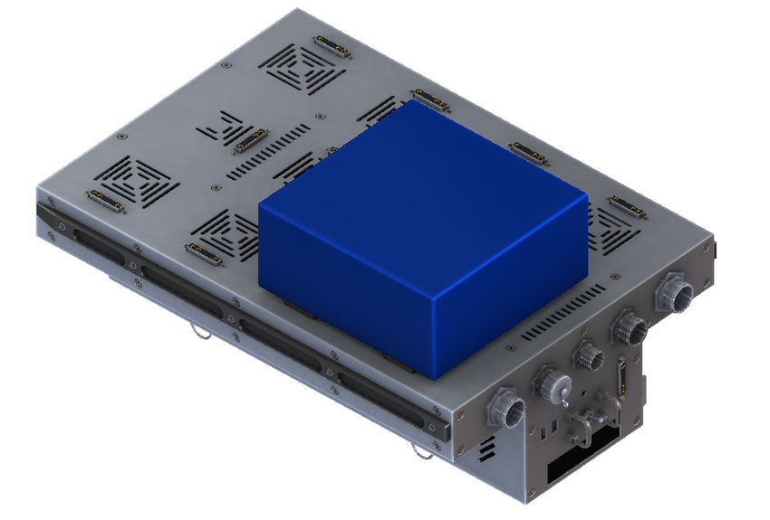
Reference :           ICU-SA-RQ-004
                                                                                                    Version :                       1.3.0
                                                                                                    Date      :              29-Aug-2018
                                                                                                    Page      :                         7

                                          ICE Cubes Facility to Experiment Cube IRD

        4.3         Experiment Cube Unit-to-System Testing ...................................................................... 43
Appendix A Verification Matrix ........................................................................................................ 44
Appendix B Drawings ....................................................................................................................... 47
Appendix C Random Vibration Loads ............................................................................................. 48
Appendix D Typical Timeline and Required Documents ............................................................... 49

                                                        List of Figures
Figure 1 ICE Cubes Facility closed and open views ............................................................................. 13
Figure 2 Framework features ................................................................................................................ 14
Figure 3 Framework with one 2Ux2U Experiment Cube ....................................................................... 15
Figure 4 1U Experiment Cube with protruding male DB13W3P connector .......................................... 15
Figure 5 J01 to J08 connectors positions on the bottom of the Framework ......................................... 16
Figure 6 J09 to J20 connectors positions on the top of the Framework ............................................... 16
Figure 7 ICF sliding door position relative to ICF connector J09 .......................................................... 17
Figure 8 ICF sliding door size (as seen from inside the ICF Container) ............................................... 18
Figure 9 Accommodation of wired external payload (concept) ............................................................. 19
Figure 10 Connectors on the front of the ICF ........................................................................................ 19
Figure 11 AUX LAN J22 connector on the front of the ICF Framework ................................................ 20
Figure 12 Schematics of the forced air cooling inside the ICF Container (top view) ............................ 21
Figure 13 DB13W3P male plug (Cube side) ......................................................................................... 22
Figure 14 Protrusion of the DB13W3P male connector from the Cube wall ......................................... 22
Figure 15 Proper positioning of the DB13W3P connector on a 1U Cube (dimensions in mm) ............ 23
Figure 16 Experiment Cube standard form factors ............................................................................... 24
Figure 17 DB13W3S schematic (receptacle, Framework side) ............................................................ 28
Figure 18 DB13W3P schematic (plug, Cube side) ................................................................................ 29
Figure 19 DB13W3 pin assignment ....................................................................................................... 29
Figure 20 E-field radiated emission limits (RE02 test method) ............................................................. 31
Figure 21 AC magnetic radiated emission limits (RE01 test method) ................................................... 31
Figure 22 Radiated susceptibility E-field limit (RS03 test method) ....................................................... 32
Figure 23 Radiated susceptibility B-field limit (RS01 test method) ....................................................... 33
Figure 24 Limits for conducted susceptibility (sine wave) (CS01/CS02 test methods) ......................... 33
Figure 25 Transient pulse definition (CS06 test method) ...................................................................... 34
Figure 26 ICE Cubes communications (concept) .................................................................................. 41

                                   Copyright by Space Applications Services – All Rights Reserved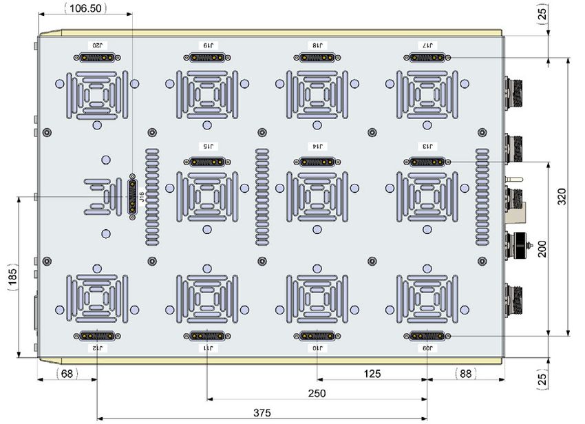
Reference :           ICU-SA-RQ-004
                                                                                                    Version :                       1.3.0
                                                                                                    Date      :              29-Aug-2018
                                                                                                    Page      :                         8

                                          ICE Cubes Facility to Experiment Cube IRD

                                                         List of Tables
Table 1 Experiment Cubes standard external dimensions.................................................................... 24
Table 2 Continuous noise limits ............................................................................................................ 25
Table 3 Environmental conditions ......................................................................................................... 26
Table 4 Launch and landing load factors envelope ............................................................................... 27
Table 5 ICE Cubes Internet protocols ................................................................................................... 35
Table 6 LOS impact on communications between a UHB and its Experiment Cube............................ 42
Table 7 Cut-out dimensions for front and rear mounting methods for DB13W3P connector (mm). ..... 47
Table 8 Random vibration environment attenuated by 76mm of bubblewrap ....................................... 48
Table 9 Random vibration test profile enveloping Space X Dragon and Orbital Cygnus ..................... 48
Table 10 Experiment Cube Timeline ..................................................................................................... 49
Table 11 Documents to be produced by the customer ......................................................................... 49

                                   Copyright by Space Applications Services – All Rights Reserved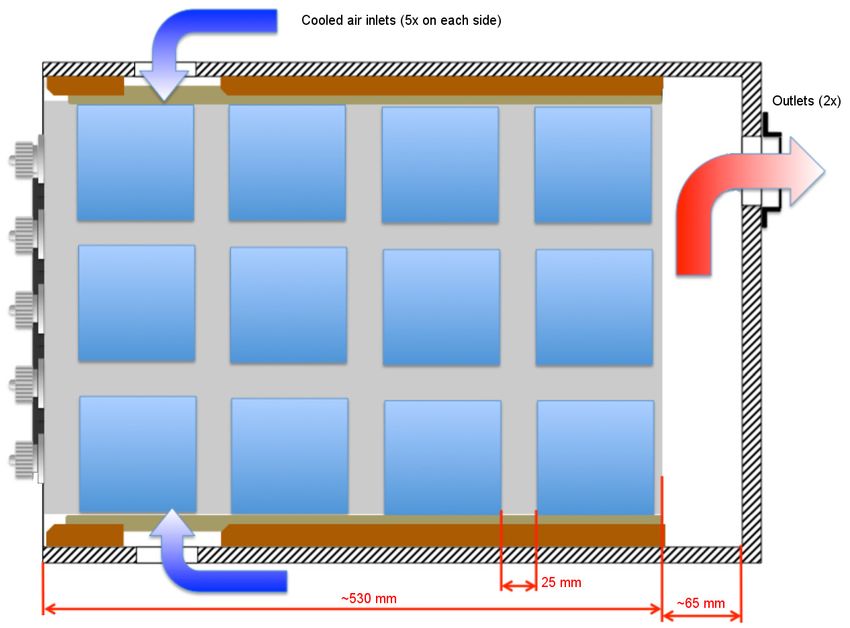
Reference :   ICU-SA-RQ-004
                                                                                 Version :               1.3.0
                                                                                 Date      :      29-Aug-2018
                                                                                 Page      :                 9

                              ICE Cubes Facility to Experiment Cube IRD

1        Introduction

1.1      Purpose and Scope
This Interface Requirements Document (IRD) defines the requirements on external interfaces between
the ICE Cubes Facility (ICF) and the Experiment Cube to be accommodated inside it when using the
ICE Cubes service. In addition, this IRD provides requirements for design and testing of the Experiment
Cube, and software interface requirements necessary for the customer to communicate from ground
with his/her Experiment Cube in orbit.

This IRD is to be complemented by the guidelines ICU-SA-TN-011 [RD1] and ICD Template ICU-SA-
ICD-002 [RD2].

All three documents are updated at regular intervals. Before proceeding, the reader shall ensure to be
in possession of the latest versions by checking on our website: http://icecubesservice.com/

As the individual Experiment Cube is developed, appropriate sections of the IRD will serve as the basis
for establishing a specific Experiment Cube Interface Control Document (ICD) to be agreed with the ICE
Cubes service provider, i.e. Space Applications Services. The ICD (established from the ICD template
[RD2]) shall take over precedence over the IRD for the Experiment Cube for which an ICD exists.

The sections on Experiment Cube requirements take into account the relevant documents listed in §1.3,
and incorporate the technical requirements of the latter documents to the maximum extent compatible
with the technical limitations of the ICF and the programmatic constraints of the ICF development
programme.

1.2      Applicable Documents
The following document establishes requirements that are applicable to the Experiment Cubes.

AD1      deleted

1.3      Reference Documents
The following documents provide information useful in the design, development and verification of the
Experiment Cube. The requirements directly applicable to the Experiment Cube have been already
reported in this IRD, and as such the documents below do not need to be considered as applicable.

RD1      Space Applications Services – Guidelines for Experiment Cube Design and Development,
         ICU-SA-TN-011, latest version

RD2      Space Applications Services – Experiment Cube to ICE Cubes Service ICD Template, ICU-
         SA-ICD-002, latest version

RD3      OHB System AG – Science Module Interface Requirements Document (SMIRD) for the
         European Physiology Model (EPM), EPM-OHB-RQ-0001, Issue 4, 30-Apr-2010 (+ relevant
         IRNs)

RD4      Astrium – Columbus Pressurized Payloads Interface Requirements Document, COL-RIBRE-
         SPE-0164, Issue 2A, 15-Nov-2013 (+ relevant IRNs)

RD5      NASA – ISS Pressurized Volume Hardware Common Interface Requirements Document:
         International Space Station Program, SSP 50835, Rev. D, April 2013 (+ associated PIRNs)

                         Copyright by Space Applications Services – All Rights Reserved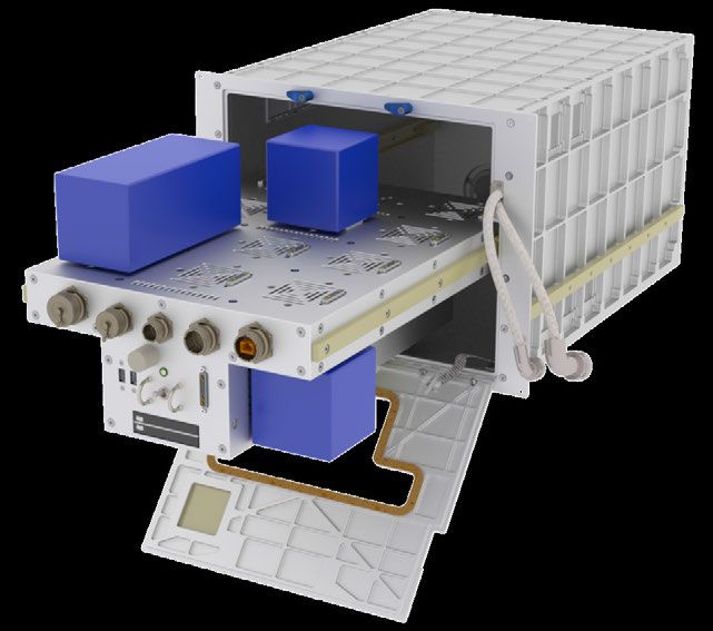
Reference :   ICU-SA-RQ-004
                                                                               Version :               1.3.0
                                                                               Date      :      29-Aug-2018
                                                                               Page      :                10

                            ICE Cubes Facility to Experiment Cube IRD

RD6    Space X – C3-1 Dragon Interface Definition Document, SPX-00001047, Version 21, 14-Aug-
       2014

RD7    Astrium – Columbus Payload Engineering Integration Requirements, ESO-IT-TN-0173,
       Issue 5, 16-Jun-2017

RD8    ESA – Security Requirements for LAN Connected Payloads, ESA-ISS-COL-SEC-RS-0002,
       Issue 1, 14-Oct-2014

RD9    ISO – General tolerances -- Part 1: Tolerances for linear and angular dimensions without
       individual tolerance indications, ISO 2768-1:1989, 02-Nov-1989

RD10   ISO – General tolerances -- Part 2: Geometrical tolerances for features without individual
       tolerance indications, ISO 2768-2:1989, 02-Nov-1989

RD11   ISO – Space systems -- Safety and compatibility of materials -- Part 1: Determination of
       upward flammability of materials, ISO 14624-1:2003, 01-Jun-2003

RD12   ISO – Space systems -- Safety and compatibility of materials -- Part 2: Determination of
       flammability of electrical-wire insulation and accessory materials, ISO 14624-2:2003, 01-Jun-
       2003

RD13   Underwriters Laboratories – Standard for Tests for Flammability of Plastic Materials for Parts
       in Devices and Appliances, UL 94, 6th edition, 28-Mar-2013

RD14   IETF – Network Time Protocol Version 4: Protocol and Algorithms Specification, RFC 5905,
       Jun-2010

RD15   IETF – Transmission Control Protocol, RFC 793, Sep-1981

RD16   IETF – User Datagram Protocol, RFC 768, 28-Aug-1980

RD17   ESA – Columbus EMC & Power Quality Requirements, COL-ESA-RQ-014, Issue 2 Rev. E,
       10-Dec-2001

RD18   USDOD – Measurement of Electromagnetic Interference Characteristics, MIL-STD-462, 31-
       Jul-1967 (+ Notice 1, 1-Aug-1968, and Notice 2, 1-May-1970)

RD19   CENELEC – Electromagnetic compatibility of multimedia equipment - Emission requirements
       (CISPR 32:2015/COR1:2016), EN 55032:2015/AC:2016-07, Jul-2016

RD20   ISS Exploitation Programme SCB – System Hardening by Operating System Patching, OPS-
       SCB-DIR-004, Issue 0 Rev. 2 draft

1.4    Acronyms
AD           Applicable Document
AOS          Acquisition of Signal
CCSDS        Consultative Committee for Space Data Systems
CD           Cube Detection
CENELEC      European Committee for Electrotechnical Standardization
CFDP         CCSDS File Delivery Protocol
COTS         Commercial Off The Shelf
CTB          Cargo Transfer Bag
DC           Direct Current
DDS          Data Distribution Service

                       Copyright by Space Applications Services – All Rights Reserved
Reference : ICU-SA-RQ-004
Version : 1.3.0
Date : 29-Aug-2018
Page : 11
ICE Cubes Facility to Experiment Cube IRD
DML Declared Materials List
EDR European Drawer Rack
EMC Electromagnetic Compatibility
EMI Electromagnetic Interference
EPM European Physiology Module
ESA European Space Agency
ESD Electrostatic Discharge
FSR Flight Safety Review
FTP File Transfer Protocol
GND Ground
GRE Generic Routing Encapsulation
HK Housekeeping
H&S Health and Status
HTTP Hypertext Transfer Protocol
HTTPS HTTP Secure
HTV H-II Transfer Vehicle
ICD Interface Control Document
ICE Cubes International Commercial Experiment Cubes
ICF ICE Cubes Facility
ICMCC ICE Cubes Mission Control Centre
ICMP Internet Control Message Protocol
IETF Internet Engineering Task Force
IP Internet Protocol
IRD Interface Requirements Document
IRN Interface Revision Notice
ISO International Organization for Standardization
ISS International Space Station
LAN Local Area Network
LED Light-Emitting Diode
LOS Loss of Signal
MEVR Maximum Effective Vent Ratio
N/A Not Applicable
NASA National Aeronautics and Space Administration
NLT Not Later Than
NTP Network Time Protocol
OS Operating System
PDR Preliminary Design Review
PIRN Preliminary Interface Revision Notice
PKI Public Key Infrastructure
RD Reference Document
RDT Real Data Transport
RFB Remote Framebuffer
RID Review Item Discrepancy
RTCP RTP Control Protocol
RTP Real-time Transport Protocol
RTPS Real Time Publish Subscribe
RTSP Real Time Streaming Protocol
SFTP SSH File Transfer Protocol
SCB Security Control Board
SPL Sound Pressure Level
SSD Solid State Drive
SSH Secure Shell
SSL Secure Sockets Layer
TBC To Be Confirmed
TBD To Be Determined
TC Telecommand
Copyright by Space Applications Services – All Rights ReservedReference : ICU-SA-RQ-004
Version : 1.3.0
Date : 29-Aug-2018
Page : 12
ICE Cubes Facility to Experiment Cube IRD
TCP Transmission Control Protocol
TIM Technical Interchange Meeting
TLS Transport Layer Security
TM Telemetry
U Unit (= 10 x 10 x 10 cm)
UDP User Datagram Protocol
UHB User Home Base
USB Universal Serial Bus
USDOD United States Department of Defense
VNC Virtual Network Computing
VPN Virtual Private Network
WAP Wireless Access Point
WLAN Wireless Local Area Network
XLS Microsoft Excel Spreadsheet File Format
XML Extensible Markup Language
XTCE XML Telemetric and Command Exchange
Copyright by Space Applications Services – All Rights ReservedReference : ICU-SA-RQ-004
Version : 1.3.0
Date : 29-Aug-2018
Page : 13
ICE Cubes Facility to Experiment Cube IRD
2 ICE Cubes Flight Segment Overview
This section provides an overview of the ICE Cubes Facility (ICF). Detailed information and interface
requirements are provided in section 3 and section 4.
2.1 The ICE Cubes Facility (ICF)
The main characteristics in terms of physical conceptual configuration are briefly highlighted in the
following.
The ICE Cubes Facility (ICF) is composed of:
• The Framework, accommodating up to 20 Experiment Cubes, and providing power and
data/commands connectivity.
• The structural Container, to be installed and mechanically fastened inside the hosting rack (EPM)
on board Columbus.
• Removable mass memory storage devices, namely the Solid State Drives (SSDs) and USB
flash drives necessary to host the operational software and to physically download the scientific
data.
The Experiment Cubes are standardized plug-and-play research modules (1U = 10cmx10cmx10cm)
or modular combinations of that basic size.
Views of the ICF with the Framework and the Experiment Cubes are shown in Figure 1.
ICF Container
Sliding door
(within the
hinged door)
Cooled air inlets
(5x on each side
of the Container)
Experiment Cubes (one
2U and two 1U shown)
ICF Framework
Figure 1 ICE Cubes Facility closed and open views
Copyright by Space Applications Services – All Rights ReservedReference : ICU-SA-RQ-004
Version : 1.3.0
Date : 29-Aug-2018
Page : 14
ICE Cubes Facility to Experiment Cube IRD
2.2 The Framework
The Framework (Figure 2) is the central unit that accommodates each Experiment Cube and offers
services such as power, connectivity and data storage.
It offers:
• Up to 20 active locations (power + gigabit Ethernet) for the accommodation and management of
“internal” Experiment Cubes, each location is equipped with one DB13W3S female receptacle (J01
to J20, cf. Figure 5 and Figure 6).
• 1 active location (in the front), J21, for the accommodation/interfacing of an Experiment Cube
located externally to the ICF and connected via a cable (see Figure 9)
• 1 Wireless Access Point (WAP) for the management of Experiment Cubes hosted in Columbus and
connected via a private Wireless Local Area Network (WLAN) generated by the ICF.
• 2 USB 3.0 Type-A ports (in the front) used, e.g. for connecting USB flash drives
• 1 auxiliary LAN connector, J22 (RJ45 port)
The system, including the Experiment Cubes, is monitored and operated from ground.
Nominal interventions of the astronauts are limited to activation of power switch, exchange of
Experiment Cubes and, if requested, installing/removing the SSD and USB flash drives used for
collection of large amounts of scientific data to be physically downloaded to ground.
DB13W3 receptacles to
plug Experiment Cubes
Air cooling slits
Auxiliary LAN
connector J22
(dust cap on)
Sliding guides for
accommodation in
Container
Two USB 3.0 slots LAN port to/from ground
(J23 & J24)
DB13W3 receptacle J21
for one “external” Cube
Power switch
Hosting bay for two
removable SSDs
Figure 2 Framework features
Copyright by Space Applications Services – All Rights ReservedReference : ICU-SA-RQ-004
Version : 1.3.0
Date : 29-Aug-2018
Page : 15
ICE Cubes Facility to Experiment Cube IRD
2.3 “Internal” Experiment Cubes
The “internal” Experiment Cubes (hereafter referred to as “Experiment Cubes” or “Cubes”) can vary per
experiment but will all have to meet basic interface requirements with the Framework such as modular
size, weight, interface, maximum allowable power, etc.
The size of the Experiment Cubes is set to mimic the CubeSat standard, i.e. 10x10x10cm (1 litre) for a
1U Experiment Cube, 20x10x10cm for a 2U Experiment Cube, etc. with one principal difference: the
Experiment Cubes can be scaled along two axes in order to offer more flexibility to customers.
Figure 3 Framework with one 2Ux2U Experiment Cube
Figure 4 1U Experiment Cube with protruding male DB13W3P connector
Copyright by Space Applications Services – All Rights ReservedReference : ICU-SA-RQ-004
Version : 1.3.0
Date : 29-Aug-2018
Page : 16
ICE Cubes Facility to Experiment Cube IRD
The Experiment Cubes can be functionally interconnected via the network offered by the Framework.
The ICF housekeeping and the scientific data will be stored on a removable SSD and will be downlinked
to ground according to the capabilities offered by the ISS infrastructure.
2.3.1 Experiment Cube Locations on the ICF
Different voltages (5V and/or 12V) and power profiles are available for each Experiment Cube location.
Figure 5 J01 to J08 connectors positions on the bottom of the Framework
Figure 6 J09 to J20 connectors positions on the top of the Framework
Copyright by Space Applications Services – All Rights ReservedReference : ICU-SA-RQ-004
Version : 1.3.0
Date : 29-Aug-2018
Page : 17
ICE Cubes Facility to Experiment Cube IRD
2.3.2 ICF Sliding Door
The Container door features a smaller sliding door (cf. Figure 1). This sliding door allows a limited access
to possible special Cubes located on top of the J09 connector of the Framework. Indeed, a class of
special Cubes may be able to host experiment cartridges (e.g. 20x40x80mm), which may require to be
replaced more frequently than the Cubes and/or while the ICE Cubes Facility remains powered.
For making use of this sliding door, please contact the ICE Cubes service.
Figure 7 ICF sliding door position relative to ICF connector J09
Copyright by Space Applications Services – All Rights ReservedReference : ICU-SA-RQ-004
Version : 1.3.0
Date : 29-Aug-2018
Page : 18
ICE Cubes Facility to Experiment Cube IRD
Figure 8 ICF sliding door size (as seen from inside the ICF Container)
2.4 “External” Experiment Cubes and Other Payloads
The requirements in this IRD have mostly been defined for “internal” Experiment Cubes. Nevertheless,
“external” Experiment Cubes or other payloads can be physically accommodated outside the ICF and
connected to the ICF via:
• Wi-Fi
• the front DB13W3S female receptacle (J21) of the Framework
• the auxiliary LAN connector (J22) of the Framework
• the USB 3.0 Type-A ports (J23 / J24) of the Framework.
For making use of any of these interfaces, please contact the ICE Cubes service.
The concept for the accommodation of wired external payloads is shown in Figure 9. The “external”
Experiment Cube could for example be attached via a bogen arm to the seat track next to the ICF.
Copyright by Space Applications Services – All Rights ReservedReference : ICU-SA-RQ-004
Version : 1.3.0
Date : 29-Aug-2018
Page : 19
ICE Cubes Facility to Experiment Cube IRD
Seat track
LAN cable to/from Columbus
“External” Experiment Cube
(20x20x30cm shown)
“External” Experiment Cube
to ICF J21 connection cable
Figure 9 Accommodation of wired external payload (concept)
Figure 10 Connectors on the front of the ICF
Copyright by Space Applications Services – All Rights ReservedReference : ICU-SA-RQ-004
Version : 1.3.0
Date : 29-Aug-2018
Page : 20
ICE Cubes Facility to Experiment Cube IRD
2.4.1 ICF J21 Connector (DB13W3S)
The front DB13W3S receptacle (J21) of the Framework is almost identical in all aspects to the twenty
other DB13W3S receptacles (J01 to J20) on the Framework, as defined in §3.1.1 and §3.4. The only
difference is the fact that there is one #4-40UNC-threaded jackpost on each side of J21 (cf. Figure 10)
to better secure a mated plug using two jackscrews.
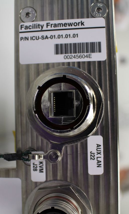
2.4.2 ICF J22 Connector (RJFTV71N)
The AUX LAN connector (J22) provides a Gigabit Ethernet interface to the ICF. The connector is an
Amphenol RJFTV71N receptacle with key coding A (cf. Figure 11). The pin assignment follows the
commonly used ANSI/TIA-568 standard. It can be interfaced using a typical RJ45 plug, which may (or
not) be encased in an Amphenol RJFTV6MN or RJFTV6N shell.
Figure 11 AUX LAN J22 connector on the front of the ICF Framework
2.5 Thermal Cooling
The ICF thermal dissipation concept is based on forced air cooling provided by the hosting rack.
The warm air is sucked from two air outlets located on the rear panel of the Container, while the cold air
enters from the ten inlets on the side walls of the Container.
Copyright by Space Applications Services – All Rights ReservedReference : ICU-SA-RQ-004
Version : 1.3.0
Date : 29-Aug-2018
Page : 21
ICE Cubes Facility to Experiment Cube IRD
Figure 12 Schematics of the forced air cooling inside the ICF Container (top view)
Copyright by Space Applications Services – All Rights ReservedReference : ICU-SA-RQ-004
Version : 1.3.0
Date : 29-Aug-2018
Page : 22
ICE Cubes Facility to Experiment Cube IRD
3 Experiment Cube Flight Interface Requirements
3.1 Mechanical Requirements
3.1.1 Experiment Cube Connector
Figure 13 DB13W3P male plug (Cube side)
The Experiment Cube shall have a DB13W3P male connector protruding from one external Cube wall
(cf. Figure 4). This protrusion (p in Figure 14) shall be comprised between 3 and 7.2 mm.
DB13W3 male plug
protruding screw head (if any)
>3mm
protrusion p
Cube wall
Figure 14 Protrusion of the DB13W3P male connector from the Cube wall
A mechanical interface drawing of the DB13W3P connector that is required for compatibility with the
ICF is included in Appendix B.1.
For a 1U Experiment Cube, the positioning of the connector on the Cube shall comply with Figure 15.
For positioning of the connector(s) on larger Cubes and/or Cubes requiring more than one DB13W3P
connector (see Figure 5 and Figure 6 for the positions of the various DB13W3S connectors on the
Framework), please coordinate with the ICE Cubes service.
Copyright by Space Applications Services – All Rights ReservedReference : ICU-SA-RQ-004
Version : 1.3.0
Date : 29-Aug-2018
Page : 23
ICE Cubes Facility to Experiment Cube IRD
Figure 15 Proper positioning of the DB13W3P connector on a 1U Cube (dimensions in mm)
Note: In agreement with the ICE Cubes service, the coordinate system for the Experiment Cube may
be different than the one pictured in Figure 15.
3.1.2 Outer Surfaces
No object or element shall protrude from the external walls of the Experiment Cube, with the following
exceptions:
• the aforementioned connector (see req. 3.1.1),
• heads of eventual screws fastening the aforementioned connector (cf. Figure 14),
• heads of eventual screws fastening the Experiment Cube walls (see also req. 3.1.6),
• eventual fins (see req. 3.1.3).
Note: Cubes requiring a different setup need prior approval from the ICE Cubes service.
3.1.3 Fins, Vents and Fans
For Experiment Cubes requiring objects or elements which have the potential to significantly alter the
direction and/or speed of the forced air flow around the Experiment Cube (e.g. fins, vents and/or fans),
please coordinate with the ICE Cubes service for more information and approval.
Copyright by Space Applications Services – All Rights ReservedReference : ICU-SA-RQ-004
Version : 1.3.0
Date : 29-Aug-2018
Page : 24
ICE Cubes Facility to Experiment Cube IRD
3.1.4 Standard Form Factors
The Experiment Cube can range in size from 1U to 4Ux3U, as illustrated in Figure 16.
2Ux1.5U
4Ux2U
3Ux2U
3Ux3U 2Ux2U 2U 4Ux3U
1.5U 1U 4U 3U
Figure 16 Experiment Cube standard form factors
3.1.5 Dimensions & Tolerances
The Experiment Cube shall have external dimensions as per one of the lines in Table 1.
Cube Form Factor Cube External Dimensions*
1U 100mm x 100mm x 100mm
1.5U 162.5mm x 100mm x 100mm
2U 225mm x 100mm x 100mm
3U 350mm x 100mm x 100mm
4U 475mm x 100mm x 100mm
2U x 1.5U 225mm x 162.5mm x 100mm
2U x 2U 225mm x 225mm x 100mm
3U x 2U 350mm x 225mm x 100mm
3U x 3U 350mm x 350mm x 100mm
4U x 2U 475mm x 225mm x 100mm
4U x 3U 475mm x 350mm x 100mm
* excluding the exceptions per requirement 3.1.2
Table 1 Experiment Cubes standard external dimensions
Note: Cubes requiring different dimensions need prior approval from the ICE Cubes service.
Dimensions shall have standard tolerances, as specified in ISO 2768-1 [RD9] for linear and angular
dimensions and in ISO 2768-2 [RD10] for features. The applicable tolerance classes are “m” and “K”,
respectively.
Copyright by Space Applications Services – All Rights ReservedReference : ICU-SA-RQ-004
Version : 1.3.0
Date : 29-Aug-2018
Page : 25
ICE Cubes Facility to Experiment Cube IRD
3.1.6 Sharp Edges
To prevent inadvertent injury to the astronauts, the external surfaces of the Experiment Cube shall not
have sharp edges, sharp corners and/or sharp protrusions.
The sharp edges verification shall make use of a cotton glove that should not be snagged as it passes
over all of the Cube surfaces (including the protruding connector, etc. per req. 3.1.2).
3.1.7 Audible Noise
3.1.7.1 Continuous Noise Limits
The total unweighted Sound Pressure Level (SPL) generated by the Experiment Cube in the noisiest
functioning conditions shall be measured at a fixed distance from the noisiest Cube surface in all octave
bands between 63Hz and 8000Hz (i.e. 63Hz, 125Hz, 250Hz, 500Hz, 1kHz, 2kHz, 4kHz and 8kHz). This
distance is 60cm for an “external” Cube, and can vary from 61cm to 98.5cm for an “internal” Cube, to
be coordinated with the ICE Cubes service.
For continuous noise (i.e. more than 8 hours per 24-hour period), the limit levels defined in Table 2 shall
not be exceeded in any octave band.
Frequency 63Hz 125Hz 250Hz 500Hz 1kHz 2kHz 4kHz 8kHz
Limit (“internal”, TBC) 60dBL 50dBL 39dBL 35dBL 34dBL 32dBL 33dBL 35dBL
Limit (“external”, TBC) 64dBL 56dBL 50dBL 45dBL 41dBL 39dBL 38dBL 37dBL
Table 2 Continuous noise limits
Note: If the noise generated by the Experiment Cube is lower than 26dBA (A-weighted dB) when
measured at 61cm from the noisiest Cube surface in the noisiest functioning conditions, the above-
specified measurement is in principle not required. Please contact the ICE Cubes service for details.
3.1.7.2 Intermittent Noise Limits
In case of intermittent noise generated by the Experiment Cube, i.e. less than 8 hours per 24-hour
period, the acceptable noise limits can be higher than the values defined in Table 2 and they shall be
agreed with the ICE Cubes service.
3.1.7.3 Audible Noise Limits Verification
The requirements of audible noise produced by the Experiment Cube can be verified by:
• Analysis based on the datasheets of the commercial parts, if available
• Test
The test setup and procedure (including success criteria) shall be agreed between the ICE Cubes
service and the customer.
3.1.8 Microgravity Disturbances
Microgravity disturbances generated by the Experiment Cube at the level of the mechanical interface
with the ICF shall be limited.
For Experiment Cubes containing moving parts, please coordinate with the ICE Cubes service.
Copyright by Space Applications Services – All Rights ReservedReference : ICU-SA-RQ-004
Version : 1.3.0
Date : 29-Aug-2018
Page : 26
ICE Cubes Facility to Experiment Cube IRD
3.2 Structural and Environmental Interface Requirements
3.2.1 Environmental Conditions
3.2.1.1 Temperature, Pressure and Humidity Conditions
To guarantee mission success (reliability-related, see req. 3.10), the Experiment Cube should be able
to withstand the ISS, HTV, Progress, Soyuz, SpaceX Dragon, and Orbital Cygnus humidity, temperature
and atmospheric pressure requirements as summarized here below (from COL-RIBRE-SPE-0164 [RD4]
and SSP 50835 [RD5]).
Temperature (°C) Pressure (mbar) Maximum Relative
Humidity (%)
Storage +5 to +35 942 to 1050 85
Transport -10 to +50* 150 to 1060 90
Accommodation into 0 to +50 600 to 1293 85
launcher
Launch / Ascent 0 to +50 0 to 1293 90 (100 depressed)
On Orbit (on board the +0 to +50 0 to 1050 70 (100 depressed)
ISS) non operational
Descent / Landing 0 to +48,9 0 to 1293 90 (100 depressed)
* In the event of a launch in Progress or Soyuz, the temperature range requirement during transportation by train
to the launch site is actually -50°C to +50°C. However, this temperature range can be narrowed to -10°C to +50°C
by shipping the hardware items from Space Applications Services’ premises to the launch site in such a way that
no transportation in an uncontrolled temperature environment takes place (as it has been done in the past for other
projects). Therefore, it is considered appropriate to verify compliance of the Experiment Cube design against the -
10°C to +50°C range.
Table 3 Environmental conditions
For Experiment Cubes with special temperature and/or humidity control requirements (on board, during
launch, and/or return to ground), please coordinate with the ICE Cubes service.
3.2.1.2 Depressurization/Re-Pressurization Conditions
The Experiment Cube shall be compatible with the following:
• The maximum depressurization/re-pressurization rates during transport (ascent/descent) of
13.3 kPa/s and 798 Pa/s, respectively.
• The depressurization/re-pressurization rates on board the ISS of 878 Pa/s (for at least 2 min,
starting at ambient pressure), and 230 Pa/s (for at least 3 min, starting at p = 100 Pa).
• The pressure gradient that may occur due to fire suppression in the rack where the ICF is
hosted, with a peak pressurization rate of 20 kPa/s (for less than 0.1 second in the case of
manual fire suppression).
Note: To guarantee that no significant mechanical stress is applied on enclosed (not intentionally sealed)
structures during depressurization or re-pressurization, vents in each enclosure should be implemented
such that the Maximum Effective Vent Ratio (MEVR) = internal volume (cm³) / effective vent area (cm²)
≤ 5080 cm. Enclosures verifying this criterion will not need any depressurization/re-pressurization test
nor structural analysis.
Copyright by Space Applications Services – All Rights ReservedReference : ICU-SA-RQ-004
Version : 1.3.0
Date : 29-Aug-2018
Page : 27
ICE Cubes Facility to Experiment Cube IRD
3.2.1.3 Thermal Environment inside the ICE Cubes Facility
The cooling of the Experiment Cube is obtained via forced air ventilation inside the ICF.
The temperature of the cooled air flow entering the ICF Container can range between 17°C and 30°C
(hosting rack design values). Measurements performed in the past range between 20°C and 25°C.
Approximate temperature of the air surrounding the Experiment Cube, if requested, can be offered by
proper location of the Cube itself in the ICF.
Fine temperature control shall be implemented at Cube level by the introduction of heaters, fins, vents,
fans (see req. 3.1.3) or Peltier coolers, as necessary.
3.2.2 Launch & Landing Loads
The Experiment Cube safety-critical and interface-critical structures shall provide positive margins of
safety when exposed to the accelerations documented in Table 4 at the centre of gravity of the Cube
soft stowed in bags (soft packaging in principle provided by the ICE Cubes service), with all six degrees
of freedom acting simultaneously.
Nx (g) Ny (g) Nz (g) Rx (rad/s²) Ry (rad/s²) Rz (rad/s²)
Launch +/-7.4 +/-7.4 +/-7.4 +/-13.5 +/-13.5 +/-13.5
Landing +/-10.0 +/-10.0 +/-10.0 N/A N/A N/A
Table 4 Launch and landing load factors envelope
Safety-critical and interface-critical structures within an Experiment Cube will be identified by the ICE
Cubes service, based on the peculiarities of the Experiment Cube.
3.2.3 Random Vibration Loads
The Experiment Cube safety-critical and interface-critical structures packed soft stowed in bags (soft
packaging in principle provided by ICE Cubes service) shall meet the specified performance
requirements when exposed to the maximum flight random vibration environments defined in Appendix
C (from Table 3.1.1.2.1.2.3.1-1 of SSP 50835 [RD5]).
Safety-critical and interface-critical structures within an Experiment Cube will be identified by the ICE
Cubes service, based on the peculiarities of the Experiment Cube.
For reliability purposes (see req. 3.10), Experiment Cubes may be random vibration tested regardless
of the criticality of their structures.
Mechanical drawings of structurally qualified Cubes will be included in Appendix B.2. Cubes built
according to these drawings do not necessitate structural analysis and testing until the limits of mass
distribution (TBD) are observed.
For Experiment Cubes with different structure requirements and/or for establishing the proper vibration
test for your Cube, please coordinate with the ICE Cubes service.
3.2.4 Shock Loads
The Experiment Cube packed in foam will not experience significant mechanical shock. Shock
verification is not required for launch and return events.
Copyright by Space Applications Services – All Rights ReservedReference : ICU-SA-RQ-004
Version : 1.3.0
Date : 29-Aug-2018
Page : 28
ICE Cubes Facility to Experiment Cube IRD
Any mechanical or electrical components that are highly sensitive to shock should be assessed on a
case-by-case basis with the help of the ICE Cubes service.
3.3 Thermal Requirements
3.3.1 Temperature Control
For Experiment Cubes with special temperature control requirements (on board, during launch, and/or
return to ground), please coordinate with the ICE Cubes service.
3.3.2 Touch Temperature
Under all modes of operation, the Experiment Cube shall have no external surface exceeding the
required permissible material temperature TPM for intentional contact (any length of time). TPM depends
on the surface material characteristics and can be calculated as follows:
TPM = 17570 / I + 44.87 (expressed directly in °C).
I = (kρc)½ is the thermal inertia [J·m-2·K-1·s-½], where k is the thermal conductivity [W·m-1·K-1], ρ the density
[kg·m-3] and c the specific heat [J·kg-1·K-1].
TPM for commonly used materials is equal to: 45.8°C for aluminium alloy AA6061-T6; 47.3°C for stainless
steel AISI 316; 57.0°C for glass; 69.0°C for Teflon.
3.3.3 Thermal Sensor
Although in principle not needed, the implementation of thermal sensor(s) in the Experiment Cube may
be requested by the ICE Cubes service on a case-by-case basis.
3.3.4 Condensation Prevention
Under all modes of operation, no condensation shall occur in the internal parts or on the external surface
of the Experiment Cube.
Note: This requirement is in principle automatically verified for all Experiment Cubes without active
cooling system (e.g. Peltier cooler) that could reach a temperature ≤15°C.
3.4 Electrical Interface Requirements
3.4.1 DB13W3 Connector Proprietary Wiring
The Experiment Cube shall comply with the following proprietary pin assignment (see also req. 3.6.5).
Figure 17 DB13W3S schematic (receptacle, Framework side)
Copyright by Space Applications Services – All Rights ReservedReference : ICU-SA-RQ-004
Version : 1.3.0
Date : 29-Aug-2018
Page : 29
ICE Cubes Facility to Experiment Cube IRD
Figure 18 DB13W3P schematic (plug, Cube side)
A1 A2 A3 1 2 3 4 5 6 7 8 9 10
+12V GND +5V B+/R+ B-/R- C+ C- CD A+/T+ A-/T- D+ D- SHLD
(A to D = bidirectional Gigabit Ethernet data pairs, T = Transmit, R = Receive;
GND = Ground; CD = Cube Detection; SHLD = Ethernet cable shield)
Figure 19 DB13W3 pin assignment
The Cube Detection circuit enables to detect the presence of a recognized plugged Cube. As such, pin
5 shall be properly terminated in the Experiment Cube, as follows:
• Unless otherwise specified: electrical resistance = 0 Ω (short to ground).
• For specific cases (e.g. non-IP-enabled Cubes): resistance value between 12 kΩ and 220 kΩ to be
assigned by the ICE Cubes service.
In case 5V power is not required, the unused pin A1 shall be left unconnected in the Experiment Cube
(isolation resistance to all other pins >10MΩ).
In case 12V power is not required, the unused pin A3 shall be left unconnected in the Experiment Cube
(isolation resistance to all other pins >10MΩ).
3.4.2 Power
The Experiment Cube can make use of two different power lines: 5V @ 0.9A (thus 4.5W maximum) and
12V @ 3A (thus 36W maximum).
The maximum amount of power delivered to the Experiment Cube depends on its capability to dissipate
heat through its external surfaces (i.e. on its geometry).
For preliminary design purposes, the following maximum power consumptions shall be considered: 10W
for 1U, 15W for 1.5U, 20W for 2U, 30W for 3U and 40.5W for 4U and bigger sizes (cf. §3.1.5).
For Experiment Cubes with higher power requirements, please coordinate with the ICE Cubes service.
3.4.3 Unexpected Power Loss
The Experiment Cube shall be able to safely withstand unexpected power loss and multiple power
cycles, resulting from normal operations on board the ISS.
Copyright by Space Applications Services – All Rights ReservedReference : ICU-SA-RQ-004
Version : 1.3.0
Date : 29-Aug-2018
Page : 30
ICE Cubes Facility to Experiment Cube IRD
3.5 Electrical and Electromagnetic Compatibility (EMC) Requirements
3.5.1 Grounding, Bonding & Isolation
3.5.1.1 Grounding (i.e. Ground Return)
The grounding (i.e. input power ground return) of the Cube shall be exclusively implemented via pin A2
(GND) in the Cube DB13W3P connector.
3.5.1.2 Bonding (i.e. Chassis Ground)
There shall be no floating metal within the Experiment Cube, i.e. all substantial metallic part shall be
bonded.
Preferred bonding strategy: the Experiment Cube shall be bonded to the ICF via the metallic frame of
the DB13W3 interface connector (there is no bonding strap between the Experiment Cubes and the
ICF).
The Experiment Cube shall have a bonding resistance ≤ 2.5 mΩ DC per bonding junction between:
• different parts of the Cube metallic structure,
• DB13W3P connector shell and Cube metallic structure,
• internal bonding straps, if any, and Cube metallic structure.
In case an isolating DC/DC converter is used downstream of the DB13W3P connector, the secondary
power ground return shall be connected to the DB13W3P shell with a bonding resistance ≤ 2.5 mΩ DC.
Preferred bonding strategy for the shield: the Experiment Cube shall have a bonding resistance between
cable shield termination (Cube DB13W3P connector pin 10) and DB13W3P shell ≤ 7 mΩ DC.
Optional bonding strategy: the Cube metallic structure may be used as power ground return (e.g.
multipoint ground) and thus isolated from the DB13W3P shell (cf. req. 3.5.1.3). In such a case, the
Experiment Cube shall have a bonding resistance ≤ 2.5 mΩ DC per bonding junction between:
• different parts of the Cube metallic structure,
• internal bonding straps, if any, and Cube metallic structure.
Optional bonding strategy for the shield: the Experiment Cube cable shield termination (Cube DB13W3P
connector pin 10) shall be connected to the power ground return (pin A2) with a 10MΩ to 40MΩ resistor.
3.5.1.3 Isolation
The isolation resistance between the Cube DB13W3P connector shell and pins 1, 2, 3, 4, 6, 7, 8, 9 of
the DB13W3P connector shall be > 10MΩ.
The isolation resistance between the Cube DB13W3P connector shell and pins A1, A2 and A3 of the
DB13W3P connector shall be > 10MΩ.
The capacitive coupling between the Cube DB13W3P connector shell and pins A1, A2 and A3 of the
DB13W3P connector shall be < 220nF.
The isolation resistance between pin A1 and pin A3 of the Cube DB13W3P connector shall be > 10MΩ.
Copyright by Space Applications Services – All Rights ReservedYou can also read