AMPTEC RESEARCH - AMPTEC 630ES SAFETY IGNITER TESTER OPERATION/MAINTENANCE MANUAL
←
→
Page content transcription
If your browser does not render page correctly, please read the page content below
AMPTEC
                                       RESEARCH

                 AMPTEC 630ES
            SAFETY IGNITER TESTER
        OPERATION/MAINTENANCE MANUAL

                                                                     Revision D
PHONE (512) 858-4045; FAX (512) 858-4340; TOLL FREE IN USA 800-350-5105
website http://www.amptec.com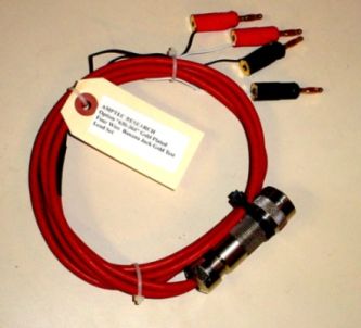
1

TABLE OF CONTENTS
_______________________________________________________________

SECTION A: UNPACKING AND INSPECTION

      A-1   Introduction to the AMPTEC 630ES
      A-2   Unpacking and Inspection
      A-3   Opening the 630ES Ohmmeter and Removal of the Lid
      A-4   AC Adaptor/ Battery Charger- Power Requirements
      A-5   Setup and Use

SECTION B: 630ES Explosive Safety Igniter Tester
           SPECIFICATIONS

            Table B-2.    Specifications

SECTION C: REPLACEMENT, OPTIONAL AND ACCESSORY
ITEMS

      C-1   Available Accessories and Options
      C-2   Test Lead Sets

SECTION D: OPERATION AND USE

      D-1   General
      D-2   Front Panel Features and Operation
      D-3   Fuse Holder
      D-4   4-Wire Resistance Measurement
      D-5   Connections
      D-6   Failsafe Operation
      D-7   Battery Monitoring Circuitry
      D-8   Zero Pot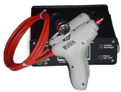
1

SECTION E: THEORY OF OPERATION

    E-1    General
    E-2    Troubleshooting
    E-3    Circuit Descriptions
    E-4    Analog-to-Digital Converter
    E-5    Ohms-to-DC Converter
    E-6    Failsafe Design
    E-7A   Ultra-Safe Power Supply Scheme
    E-7B   Failsafe Current Limiting Circuit
           Figure E-1.     Model 630ES Block Diagram
           Figure E-1B     Analog-to-Digital Converter Timing Diagram
           Figure E-2     Analog Section of IC1 and IC2
           Figure E-3.     Constant Diagram (Simplified)
           Figure E-4.     LED Display Pin Functions

SECTION F: ROUTINE MAINTENANCE

    F-1    General
    F-2    Required Test Equipment
    F-3    Calibration Procedure
    F-4    Battery Replacement Instructions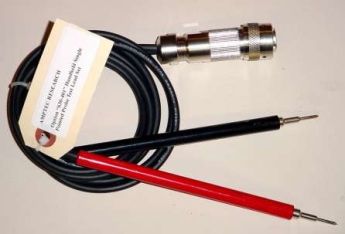
SECTION A: UNPACKING AND INSPECTION

A-1. Introduction to the AMPTEC 630ES

The AMPTEC Series 620A and now the 630
Series Igniter Testers are becoming the          A standard feature of the 630ES is a battery
standard in the Explosive Safety Igniter         monitoring circuit that alerts the user it is time to
Circuit Test industry, and are designed to       recharge the batteries. Refer to section D-7 for
                                                 more details.
provide extremely safe and reliable
resistance testing of explosive or volatile
                                                 A-2.    Unpacking and Inspection
devices. Safety Approvals from various
Safety Boards include, the U.S. Air Force (
620A-4) for generic use on Non-Nuclear           If the shipping carton (box)                  RMA
munitions. Some of the devices the 630ES         appears damaged, request that the
Failsafe Ohmmeter may be used on include:        carrier's agent (i.e. UPS) be present
fuses, squibs, igniters, explosive bolts,         when the unit is unpacked. If the instrument
automobile airbag initiators and many            appears damaged, the carrier's agent should
others.                                          authorize repairs before the unit is returned to the
                                                 factory. Even if the instrument appears
Essentially, a AMPTEC 630ES is a 4-wire          undamaged, it may have suffered internal damage
failsafe digital ohmmeter which has been         in transit that may not be evident until the unit is
designed to reliably use very low test           operated or tested to verify conformance with its
currents for its resistance measurement.         specifications. You may refer to the Functional
Additional circuitry proprietary to              Test section of Section D of this manual to help
AMPTEC RESEARCH is used to ensure                identify the problem (i.e Test leads etc.) The
                                                 630ES has a set of test resistors built-in the
that test current levels do not exceed the
                                                 Functional Test Section that can quickly help the
specified "failsafe current" even in a worst-    user figure out where the problem is most of the
case component failure situation. The            time. If the unit fails to operate or fails to meet the
failsafe feature is tested in every instrument   performance specifications of Section B, notify
before shipment.                                 the carrier's agent and the nearest AMPTEC Sales
                                                 Office. Retain the shipping carton for the carrier's
The 620A and the newer 630 series                inspection. DO NOT return equipment to
represent the latest in ultra-safe Igniter       AMPTEC RESEARCH or any of its sales offices
Tester measurements. The 630ES uses the          prior to obtaining an (RMA) Return Material
same main printed circuit board (PCB) as         Authorization number.
the AMPTEC 620A Igniter Tester. The
630ES has been made water-resistant and
has many features which make it useful in a
variety of applications. Please check the
front of this manual for any addendums that
may apply to new 630ESs and 630AN
conversions.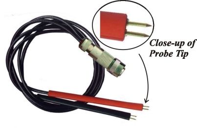
1

A-3. Opening the 630ES Igniter Tester             The 630ES has a way to remove it’s lid
and removal of the Lid                            completely, for example when used in an
                                                  indoor laboratory environment. With the
When closed, the 630ES Explosive Safety           630ES open, remove the units two hinge
Igniter Tester has two large O-rings that         pins (hex type) by twisting them. The lid
provide a very water resistant and on             should come free at the hinge. Once the lid is
occasion even an air tight seal. By               removed replace the hinge pins in the hole they
pressing down with your palm as                   were pulled out of.
diagramed above you compress the O-ring
in the lid of the 630ES.. This makes it           A-4. AC/DC Battery Charger - Power
easier to flip up the release latch. Repeat the   Requirements
palm press step on the other corner of the
630ES while flipping up the release latch.        The AMPTEC 630ES is powered by an
At this point the 630ES lid will normally be      internal rechargeable heavy-duty nickel-
able to be raised, and placed in an open lid      cadmium battery pack (4 ea D cell - 5.7 AHr).
state.
                                                  The battery charge is maintained by an
If the 630ES doesn’t open after flipping up       external AC/DC converter that plugs into a
the release latches, a change in atmospheric      standard 115VAC receptacle. The AC adapter
pressure since the unit was last closed may       provides 9VDC @ 1.1A. The AC Adapter
be the culprit. Turn the Air Pressure             Battery Charger is configured with a keyed
Equalization or “Purge Valve” counter-            connector that plugs into the “mating” keyed
clockwise. Once air-pressure is equalized,        connector on the 630ES front panel.
the 630ES can be opened. If the Purge
Valve was opened, return the valve to the         For safety reasons, the battery charger’s keyed
closed state (tighten = clockwise) once the       connector blocks access to the test lead
630ES lid is open. +                              connections that are also part of the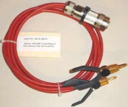
630ES Explosive Safety Igniter Tester keyed              the AC adapter must be connected for 4 hours in
connector. In this way the user may not ever be able     order to fully restore the charge. If you need a
to connect any test leads while the unit is charging.    replacement AC/DC Battery Charger for the 630A,
The 630ES is designed so it is virtually impossible to   contact the AMPTEC customer service department
be powered (in operating - measurement mode)             and request an option “630DC” Battery Charger.
directly from the AC line adapter. As an additional
note, the 630ES main power switch must also be in        A-5.   Setup and Use
the “Off/Charging” mode in order for the connected
battery charger to recharge the 630ES’s batteries.       Once the AMPTEC 630ES has had it’s batteries
                                                         charged for 12 to 24 hours it is ready for use. The
For customers using 220VAC 50 HZ AC line power           630ES consumes little power and generates virtually
for running the battery charger, please inform           no heat. Consequently, it may be used in any area
AMPTEC’s sales department at the time of your            where the environment does not exceed the
order and the appropriate adaptor will be included       specifications of Table B-2.
with the 630ES Failsafe Ohmmeter shipment for an
additional fee.                                          Avoid exposing the 630ES Explosive Safety Igniter
                                                         Tester to extremes of temperature which will affect
A fully charged battery pack may power the 630ES         accuracy and shorten battery life-span.
for approximately 8 to 10 hours before requiring a
recharge. Amptec installs a quality set of 4 each
Heavy Duty (5700 mAHr) Ni-Cad batteries. The
620A will also operate on a 4000 mAhr D cell Ni-
Cads with a shortened operating time between
charges.

The “Power” switch has two separate modes. The
“ON” position supplies internal battery isolated
power to operate the 630ES when they are charged.
If you turn on the 630ES, and the display does not
come on, it may indicate the batteries need charging.
The “OFF/CHARGING” power switch position is for
use when the batteries need charging or the 630ES is
not in use. As mentioned earlier of course the AC/DC
Battery Charger must be plugged into the 630ES’s
keyed connector to facilitate charging the batteries.

Although the batteries are fully charged prior to
shipment, it may be desirable to refresh the charge
for 24 hours before use. As a rule of thumb, the
630ES requires twice as much time to fully recharge
as the amount of discharge time. For example, if the
instrument was used continuously for 2 hours,
SECTION B - 630ES EXPLOSIVE SAFETY
IGNITER TESTER - SPECIFICATIONS
______________________________________________________________
Table B-2. Specifications
Accuracy: (for 1 year @25°C ± 10°C)
2.0 Ohm range . . . . . . . . . . . . . . . . . . . . . . . . . . . . . ±0.02% of reading ±0.05% of range
20 Ohm through 200 Ohm ranges . . . . . . . . . . . . . . . . ±0.02% of reading ±0.02% of range
200 KOhm range . . . . . . . . . . . . . . . . . . . . . . . . . . . ±0.05% of reading ±0.05% of range
Temperature Range
Operating 0°C to 50°C
Storage -10°C to 70°C
Temperature Coefficient
2.0 Ohm through 200 Ohm ranges . . . . . . ±0.002% per °C (from 0°C-15°C and 35°C-50°C)
200 KOhm ranges . . . . . . . . . . . . . ±0.005% per °C (from 0°C-15°C and 35°C-50°C)
Conversion Rate . . . . . . . . . . . . . . . . . . . . . Approximately 3 per second
Instrument Display . . (20,000 count) 4½ digit Super Bright Light Emitting Diodes (LED)
Over-Range Indication . . . . . . . . . . . . . . . . ( select next higher range) 630ES Display flashes
Measurement Update Rate . . . . . Approximately 300ms (~3 per second)
Voltage Protection - Maximum Input . . . . 250VDC or ACpeak without damage
Open Circuit Current Source Compliance Voltage . . . . . clamped at ~1.6 volts ( ± 2% )
Power . . . . (4 "D" 5.0 AHr Heavy Duty) 1.2V rechargeable nickel-cadmium batteries
Fuse . . . . . . 2 ampere fast blo (3 AG type)
AC/DC Battery Charger (Option 630DC) provides 9VDC at 1.1 Ampere nominal
Dimensions . . . . . . . . . . . . . . . . . . . . . . . . . . . . 13.5" (34.3cm) W x 12" (30.5cm) D x 6"(15.2cm) H
Weight . . . . . . . . . . . . . . . . . . . . . . . . . . . . . . 12 lbs net; 15 lbs shipping
Functional Test Section - The 630ES Functional Test Section provides added measurement integrity using a
milliammeter and test resistors to cross check the overall 630ES operation whenever desired. The test
resistors are for cross checking 630ES basic operation and should not be used for calibration purposes.
Simpsontm DC Milliammeter Range - 0-10 mA fullscale, Accuracy ±3%
2
4 6
MILLAMPERES
8 FTSR1 01-23572 0.1 Ohm 3.0 % Resistor, Tc-50ppm/°C 1/4W
10
FTSR2 01-23573 1.0 Ohm 3.0% Resistor, Tc- 50ppm/°C 1/4W
FTSR3 01-23574 10.0 Ohm 3.0% Resistor, Tc- 50ppm/°C 1/4W
FTSR4 01-23576 100.0 Ohm 3.0% Resistor, Tc- 50ppm/°C 1/4W
FTSR5 01-23580 100 KOhm 3.0% Resistor , Tc- 50ppm/°C 1/4W
FTSR6 01-23582 190 KOhm 3.0% Resistor, Tc- 50ppm/°C 1/4W
1.0 OHM
190K OHMCHAPTER C - REPLACEABLE ITEMS,
OPTIONS AND ACCESSORIES
C-1. Available Accessories and Options C-2. 630ES Test Lead and Connector Sets
This manual does not list all possible All AMPTEC Explosive Safety - Igniter Tester /
accessories that AMPTEC RESEARCH is Failsafe Ohmmeter Test Leads and Probe sets
willing to provide as a support items for the are a minimum 48" length. One end of the test
630ES Explosive Safety Meter Igniter Tester. lead set is terminated with the mating connector
Contact the sales department at AMPTEC if you for 630ES Front panel connection port (user
have a request for an item that is not described specified). AMPTEC RESEARCH's website
here. Listed below are the options available for http://www.amptec.com should also provide the
use with the AMPTEC 630ES Explosive Safety latest information on accessories available.
Meter Igniter Tester.
Option 630-300 : A 4 Terminal Kelvin Clip
Lead Set (630ES compatible)
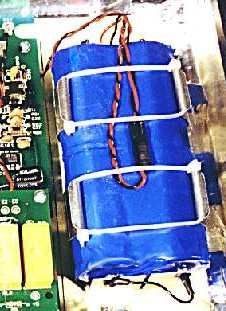
Option 630-BAT: Replacement Battery Pack
The rechargeable NICAD battery pack
installed in the 630ES Explosive Safety Meter
should provide trouble-free operation.
Replacement, however, may eventually be
necessary. The 630ES Explosive Safety Meter
battery pack uses four "D cell" - 1.2V (5.0 AHr
NICAD recommended) installed in a
rechargeable battery pack.
The option "630-300" is a shielded 48" lead set
terminating in ½" opening Gold Plated 4
Terminal Kelvin clips that is AMPTEC 630ES
(photo shows AMPTEC 630ES battery pack) compatible. The option "630-300" can clip
easily to wires, pins, and medium size (up to ½"
The reliability of the 630ES battery pack is diameter) conductors. Option "630-300" is the
estimated to be ten fold better than individual recommended Kelvin Clip four wire lead set for
batteries simply placed in the battery holder. the 630ES Series Igniter Testers. The notched
AMPTEC RESEARCH does not recommend connector end plugs directly into the 630ES’s J1
using individual NICAD batteries in lieu of the main front panel connector labeled for “test
AMPTEC 630ES battery pack, and as such leads”.
would be deemed a violation of product
warranty. To order a replacement
AMPTEC630ES Explosive Safety Meter
NICAD battery pack specify AMPTEC part
number "OP630-BAT".C-1. Available Accessories and Options The option "630-400" can clip easily to wires,
pins, and medium size (up to ½" diameter con-
This manual does not list all possible ductors). The notched connector end plugs
accessories that AMPTEC RESEARCH is directly into the 630’s J1 main front panel con-
willing to provide as a support items for the nector labeled for “test leads”.
630BN Igniter Tester. Contact the sales
department at AMPTEC if you have a request
for an item that is not described here. Listed
below are the options available for use with the
AMPTEC 630BN Igniter Tester.
Option 630-305: Separate/Twin Banana Plug
(Red tipped and Black tipped) Cable Set
Option "630-305" is a 48" long replacement
cable set normally supplied as part of the
AMPTEC 630BN Ohmmeter package. The
Option “640-305 has two single banana plugs
Option 630DC: Battery Charger (meter and common) terminated with the
630BN style notched connector. One banana
Option "630DC" is an AC/DC converter that plug is red (Voltage high and Current High) and
converts 115VAC line voltage to 9VDC at 1.1A. one banana plug lead end is black (Voltage low
The 630 Battery Charger is fitted with the and Current low) . The 4-wire configuration is
mating plug that connects to the unit’s J1 maintained up to the point of the banana plug,
connector. One charger is provided as a standard eliminating most cable resistance effects.
accessory with every 630ES Igniter Tester .
A= I High
Replacement Batteries A
G
B= V High
H F C= V Low
B
C
E D= I Low
The rechargeable NICAD batteries installed in D E=
F= Ground (-)
the 630ES should provide trouble-free G=Chassis Ground
operation. Replacement, however, will H= +5 V
eventually be necessary. The 630ES uses four
1.2V cells (5.7 AHr recommended) installed in a
reusable battery box. The batteries are held in
place by a metal retaining plate. When
ordering replacement batteries, please specify Option 630-Plug: For Custom Test Harnesses
AMPTEC Stock #05-10117, quantity four (4).
Option "630-Plug" is the 630Test Lead Plug
C-2. Test Lead and Connector Sets along with 8 gold pin/sockets for custom wir-
Option 630-400: 4 Wire Kelvin Lead Set ing/missile test harness applications.
Contact the sales department at AMPTEC
Option "630-400" is the recommended Kelvin RESEARCH (phone 1-800-350-5105 from
four wire lead set for the 630 Series Igniter inside the USA) if you have need for a special
Testers ( especially for versions that have a 2 probe, adapter, lead set, or custom option..
Ohm range). Option 630-300 is a shielded 48" AMPTEC’S engineers have helped customers
lead set terminating in ½" opening Kelvin clips. with special igniter tester accessory require-
ments. Check with our website which is
http://www.amptec.com for latest AMPTEC
RESEARCH contact (address and phone #
changes) information.SECTION C: REPLACEABLE ITEMS & ACCESSORY ITEMS CONTINUED
The AMPTEC 630ES Explosive Safety Igniter Tester is compatible with most all 630 series
accessories and test leads. Including the option "PG-401" 4 Wire Kelvin type
Pistol Grip Kelvin Probes (OP PG-401) shown below.
Option "PG-401" 4 Wire Kelvin
Pistol Grip Probes/Test Leads
Option "630-305" twin single banana jack lead set
The AMPTEC 630ES Igniter Tester test leads are normally 48" long. The 630ES uses the water-resistant
ITT Cannon Tridenttm (Test Lead mate) connector on its front panel. Most all AMPTEC 630 series
ohmmeter 4 Wire Kelvin test leads are compatible.
Option "KCS"
Kelvin Clips accept
banana jacks in back.
Option "630-403" is a 4-wire Kelvin
Handheld Probe Lead set terminated with works with
two handheld probes (2 sharp pointed gold
Option "630-304" Gold 4-Wire Kelvin Banana Jack
plated spring loaded tips per probe).
Test Lead Set ( twin single banana jack version also available)
Option "630-401" Gold 4-Wire Kelvin Option "630-304"
Single Point Probe Lead Set are 4 wire Gold 4-Wire Kelvin
to the base of each tip Clip Test Lead SetSECTION D: OPERATION AND USE
_____________________________________________________
D-1. General 630ES Front Panel Diagram.). When a given
range is selected an indicator LED informs
This section of the manual contains the user. Also note that a resistance range
complete operating instructions for the must be selected after powering up the
AMPTEC 630ES Explosive Safety Igniter 630ES in order to place it in an operational
Tester/ Failsafe Ohmmeter. A description of mode.
the front panel controls, connection
instructions, and the theory behind 4-wire Calibration Access Screws
resistance measurement is discussed in this
section. Around the perimeter of the 630ES front
panel you will note there are 10 screws
D-2. Front Panel Features and Operation (philips head type) that are used for
calibration access. These screws are meant
Power Switch to remain intact and should only be removed
by authorized personel (i.e. Calibration Lab
When the front panel power switch is placed staff).
in the OFF/CHARGE position, all power is
removed from the ohmmeter measurement Function Test Section
pins of the J1 connector (see E-6), and the
battery pack is connected to the charging The Function Test Section of the 630ES
circuit. When the switch is placed in the ON contains an analog 10 mA fullscale
position, the battery pack is disconnected milliammeter and a variety of test resistors.
from the charging circuit. In addition the With one test lead (i.e. red banana ) plugged
keyed connector on the 630ES front panel into the meter panel jack and the other test
only allows either connecting a) the battery lead (i.e. black banana lead) plugged into the
charger or connecting b) the test lead set but common panel jack, the milliammeter will
not both. The possibility of a common mode display the actual test current coming from
voltage between the device under test and the 630ES Igniter Tester.
AC Power ground is therefore completely
eliminated. The operator can not be The test resistors for the Function Test
concerned if the battery charging adapter is Section may also be used to verify general
plugged into the 630ES as it is then 630ES operation. Keep in mind the proper
impossible to make any resistance resistance range should be selected in order
measurements. to measure a selected test resistor. You can’t
measure a 1000 ohm resistor on the 20 ohm
Range Switches range of the 630ES. With one test lead (i.e.
red banana lead ) plugged into the selected
The AMPTEC 630ES input range is selected test resistor panel jack and the other test lead
by depressing the desired range switch (i.e. black banana lead) plugged into the
(silicone boot coated for water resistance) on common panel jack, the 630ES Igniter
the front panel. The pushbutton for the (20 Tester should display a resistance value
Ohm ) lowest resistance range is just below close to the labeled value of the resistor.
the display on the left, (see item 20 of the The 0.1 ohm resistor is commonly used totest the low end (i.e. linearity) of a given proof calibration sticker or seal.
630ES resistance range. The 0.1 ohm
resistor can be used to check the 630ES’s 2. Purge Valve provides air pressure
zero offset. The AMPTEC 630ES’s zero equalization to open the 630ES case after a
adjust knob can be adjusted while whilt the transit envolving an altitude change if unit
test leads are connected to the 0.1 ohm will not easily open.
resistor. The 630ES zero knob can be
adjusted until the 630ES display shows 0.1 3. Handles for lifting front plate, once the
ohms. access screws have been removed, for
calibration access
Refer the AMPTEC 630ES to qualified
service personnel (i.e Calibration Lab) if you 4. Single Access Multi-purpose Notched
suspect (i.e large error) the 630ES Main Connector - for either test lead
measurement display readings don’t agree hookup or connection to the battery charger.
with the resistor values labeled on 630ES With only one connector to the outside
Function Test Section. world, it is physically impossible to do both
at the same time. The power switch (item
AMPTEC 630ES Front Panel Diagram #21) must also be in the “Off/Charging”
while the battery charger is connected to
1. Calibration/Maintenance access screws, recharge the batteries.
also can be easily protected with a tamper5. Milliammeter for measuring test current
coming from the AMPTEC 630ES 14. Input jack for connecting to the 630ES
Ohmmeter. Plug one lead into the panel jack Ohmmeter common test lead (plug-in black
labeled “meter” and the other into the banana jack). This common jack is also
common panel jack. The Analog “Chassis Ground”. The lining of the 630ES
Milliammeter (current meter) is for Explosive Safety Igniter Tester case is
measuring actual 630ES test current (0 to 10 completely enclosed in a conductive
milliamperes fullscale). Use of the shielded Faraday Cage. The AMPTEC
milliammeter (+) panel jack and Common 630ES Faraday Cage design provides
panel jack (-) in the FUNCTION TEST additional electronic noise immunity,
SECTION with the 630ES test leads Electromagnetic Pulse (EMP) and
provides the 630ES analog millammeter test Electrostatic Discharge (ESD) protection.
current measurement connection. All measurement cabling (i.e Current high,
Voltage high, Current low, Voltage low) are
6. Negative sign at the front of the digital sheilded. The measurement leads conductive
display indicates “low battery level” - time sheilding is all connected to Chassis
to recharge. Ground (Pin G of the Single Access
Multipurpose Notched Main Connector
7. Fuse Access - required for general and the Faraday Cage) when the leads are
operation - 2 ampere fast blow type. connected to the AMPTEC 630ES
Explosive Safety Igniter Tester. This chassis
8. Zero pot - for adjusting the shorted ground common terminal may also be
resistance offset of the test lead wiring when connected to earth ground at the users
in the 2 wire mode. discretion. Chassis Grounding the 630ES
eliminates the possibility of an electrostatic
9. Keylock Switch - “Safe” mode shorts discharge coming from the 630ES to the
inputs together (locked “SAFE” with the key resistance device under test.
removed), disconnects & isolates any user
inputs from all 630ES measurement 15. 100 ohm test resistor for checking the
electronics. “Measure” mode switches user functionality of the 200 ohm range.
test lead/inputs to the 630ES Explosive
Safety Igniter Tester/Ohmmeter (the key is 16. 100K ohm test resistor for checking the
required to switch 630ES to the Measure functionality of the 200K ohm range.
mode) . Again, if the key is removed the
630ES cannot measure. 17. 190K ohm test resistor - if shunted in
parallel during an “Open Circuit” test using
10. Input jack for connecting the 630ES the 200 K ohm range, a shift < 40 counts
Ohmmeter meter test lead (plug-in red means the resistance under test is >200
banana jack) to the analog milliammeter. Megohms.
11. Input jack of 0.1 ohm test resistor for 18. Water Resistant O-ring seal(s) in lid
checking the lower end or near zero and under the edge of the front plate.
accuracy of the 2 ohm and 20 ohm range.
19. Tight Squeeze Flip Latch Area - pro-
12. 1 ohm test resistor for checking the vides a water resistant seal when closed.
mid-scale functionality of the 2 ohm range. While pressing down with palm on corner of
case, flip latch up to open.
13. 10 ohm test resistor for checking the
mid-scale functionality of the 20 ohm range.20. Resistance Ranges - 2 ohm, 20 ohm, 200 internally stepped down from the 9VDC
ohm and 200K ohm - silicone boots provide @1.1A supplied by the charger. The correct
water-resistance (small LED indicates the charging voltage is supplied by the adapter
selected range). included with the instrument. Additional
AC/DC Battery Chargers are available as
21. Power “On or OFF/Charging Switch” Option "630DC". Typically an overnight
charge (16 hours) will provide about an 6 to
22. Beveled Display Hood and Super Bright 8 hour continuous powered up life for the
LED Display ( five times brighter than 630ES. The 630ES have an internal
bright yellow, red or green LEDs). ovenized voltage reference the draws a
considerable amount of battery power when
23. Padlock Hole (i.e. security) while stored first turned on. If you know you will be
or during transit. using the 630ES again in 10 to 15 minutes,
you actually conserve battery power by not
D-3. Fuseholder and Charging System turning it off.
Fuseholder D-4. 4-Wire Resistance Measurement
The fuseholder is mounted on the front panel The four-terminal configuration of the
and contains a 2 amp in-line fuse (see item 7 630ES eliminates errors normally caused by
of the 630ES Front Panel Diagram.). This in series test lead resistance and contact
fuse is designed to protect the internal resistances. In many applications the contact
battery pack from excessive charging resistance and can exceed the value of the
currents. Replace blown fuses with the test resistance by several orders of
same type and rating only! magnitude. The 630ES overcomes this
potential error source by providing two
The Charging System terminals of constant current and an
additional two terminals for high impedance
The slimline AC to DC battery charger with voltage measurement. The result is a fast,
connector is a notched connector that mates accurate resistance measurement of the test
with only two of the 8 pin/socket mating resistance, independent of the resistance of
points on the main panel mount connector the current carrying leads.
(see Main Connector J1 Section E6 for
pinout definitions). The connection is made Figure D-1 (below) illustrates how the 4-
on the 630ES front panel (see item 4 of the wire principle is used to eliminate lead, wire
630ES Front Panel Diagram shown earlier). and contact resistances as potential error
sources. The internal current source
Again the Single Access Multipurpose inherently overcomes all series resistance
Notched Main Connector is for either test (within compliance voltage limits) and
lead hookup or connection to the battery delivers a precise constant current. The
charger but not both at the same time. With internal high-impedance DVM senses the
only one connector to the outside world, it voltage drop across the test resistance.
is physically impossible to do both at the There is negligible contact and lead
same time (charge and measure). The power resistance error created by the voltage
switch (item #21) must also be in the measurement because the high input
“Off/Charging” mode while the battery impedance of the DVM limits current flow
charger is connected in order to recharge the in the voltage leads.
batteries. The charging requirements
supplied to the internal battery pack areFor 630ES leads other than those terminated
with banana plugs, RG-58 Coax Cabling is
used. This insures that using the four wire
Kelvin measurement system - the current is
carried in the largest conductor and that the
voltage input is shielded.
In addition, the 630ES keyed test lead
connector is optionally available for
customized wiring connections , kelvin
clips, cables terminated with spade lugs, and
special banana jacks.
All AMPTEC ohmmeters use a high
impedance voltmeter as part of the
Figure D-1. Error Sources in Resistance resistance measurement process. This
Measurements eliminated with Four Wire voltmeter is a highly accurate and stable 4½
Kelvin Connections digit analog-to-digital converter (A to D).
Unless it is receiving a definite input signal,
D-5. Connections the output reading of this A to D is
ambiguous. The display may indicate a
Connections are made to the front panel randomly wandering number or it may
terminals using a 4-wire configuration as indicate an overrange condition. This
described in section D-4. Only use unpredictable display may make it seem to
AMPTEC test leads supplied with the appear that the instrument is experiencing
630ES Failsafe Ohmmeter. When using some sort of malfunction. It is, in fact, just a
AMPTEC test leads, the notched connector characteristic of the voltmeter circuit and
end plugs directly into the single access should not be mistaken for a fault in the
notched main connector (see J1 manual instrument.
section E-6) of the 630ES. Next turn the
connector clockwise until you feel the A flashing display (on and off usally all
notch or click of the mating connector of zeros) indicates an over-range condition
the 630ES. All AMPTEC 630ES leads have whenever the terminals are open, or the
the 4 wire current high, current low as well resistance under test is a higher value than
as the voltage sense high and voltage sense the selected 630ES resistance range. By
low routed to the end of the leads. The 4 using a 4-wire Kelvin type lead set or by
wire Kelvin wires then terminate in a pair of shorting the VHI and IHI terminals together
single banana plugs. One banana plug (red) and Vlow and Ilow terminals together the
for current and voltage high, and another instrument is in the 2 wire resistance mode.
banana plug (black) for current and voltage
low. All wiring including harness wires from the
two wire test connection out - are in series
The 630ES’s keyed single access connector with the test squib resistance and become
also make it extremely difficult if not part of the actual two wire measurement
virtually impossible during normal operation (another potential source of measurement
to mis-connect measurement leads to the error if not compensated for) . Many
630ES . Ordnance test procedures have the 630ES
user short their wiring harnesses at the very
end (by the squib) and record the resistancevalue or offset. Then when the 630ES leads, under test connection.) If the 630 series
including the in-series harness wiring meter doesn’t agree with the test resistors in
resistance, is connected to the test squib, the the Functional Test Section, then the meter
squib test resistance can be calculated (via or it’s test leads are most likely broken. If
subtraction of the 2 wire harness offset). this case, please contact your local
That is the 2 wire lead length shorted offset AMPTEC RESEARCH Service Office, or
resistance (without the squib resistance) can call 1-800-350-5105 or (512) 301-9333
be subtracted for the total resistance (International Overseas) or FAX (512) 301-
(including the squib resistance) to 9303, email service@amptec.com .
determine the actual squib (test) resistance.
D-6. Failsafe Operation
The display should indicate a stable reading
when the test leads are securely attached to The AMPTEC 630 series of igniter testers or
the device under test. If the display appears failsafe ohmmeters incorporate a constant
to be erroneous when connected to the current source design that renders them
resistance under test, recheck the test leads incapable of delivering excessive voltage or
for integrity and cleanliness. If all external current to the device under test. The typical
items appear to be functioning properly, the fail-safe current for each range is indicated
next step in troubleshooting is to use the under the corresponding range switch on the
Function Test Section of the AMPTEC 630 630 series meter front panel. Please refer to
series igniter tester. The Functional Test section E-6 for a technical description of the
section contains test resistors of known failsafe circuitry specifics.
value. If a measurement problem appears on
the 20 Ohm range of the meter, test for a As a further precaution the 630 series igniter
zero offset problem first. Plug the test leads tester is isolated from the AC line
into the 0.10 test resistor banana panel jack whenever the POWER switch is in the ON
built into the Functional Test Section of the position.
meter. If the meter doesn’t display a value The 630 series igniter tester receives its
close to 0.1 Ohms adjust the zero knob on power from an internal rechargeable battery
the front of the meter until it does. The zero pack (4 “D” Cell Ni-Cad batteries). The 630
adjustment knob only has enough span to series igniter tester main power switch (see
zero out the 630 series test leads. The item 21 of the 630 series igniter tester
meter’s zero adjustment knob wasn’t Front Panel Diagram) must be in the OFF /
designed to zero out a 100 feet of 2 wire CHARGING position in order to charge the
harnessing. batteries. Of course, the battery charger must
also be plugged into the unit’s keyed single
The 10.0 Ohm test resistor is also located access connector. As mentioned earlier the
Functional Test Section of the meter. The 630 series igniter tester ’s keyed single
10.0 Ohm test resistor can be used for access front panel connector allows either
testing mid-scale performance of the 20 the slim-line battery charger to be connected
Ohm range. Performing a similar Functional or the 630 series igniter tester test leads to
Test with the meter across the 10.0 Ohm test be connected to the 630 series igniter tester
resistor should get a reading close to 10.0 ohmmeter but never both simultaneously.
Ohms (i.e 9.995 Ohms is OK). If the This “keyed single access front panel
630 series Igniter Tester appears OK after connector” safety feature eliminates any
checking the test resistors in the Functional possibility of the operator measuring with
Test Section then the connect ion problem the 630ES Igniter Tester test leads while
must be outside of the 630 series meter (i.e also connected to an AC line powered
your wiring harness or the actual device adapter.D-7. Battery Monitoring Circuitry igniter tester Front Panel Diagram) is used
to adjust linearity, which effectively adjusts
The 630 series igniter tester display has a ± the “zero” of the meter. The zero can be
polarity display indicator preceding the adjusted using the “zero knob” per the
unit’s regular 4 ½ digit numeric display. maintenance section of this manual. The
The negative polarity display LED (see zero knob can also be used to counteract the
item 6 of the 630 series igniter tester Front 2 wire resistance offset encountered with
Panel Diagram) is used as a Low Battery some test lead harnesses. Checking the
indicator. 630ES “zero offset” should be one of the
first items a user does if one encounters an
If the low battery LED is illuminated, 630ES unusual or unexpected resistance level.
readings should not be trusted. An
overnight recharge should be performed
before using the 630 series igniter tester for
critical testing.
It is possible for the user to receive a low
battery indication on a single range only
(particularly the 20 ohm range), while the 630
series igniter tester remains well within
operating limits on other ranges. Unless the
user observes a continuous low battery
indication during measurement, readings
are still valid.
Notice for Cal Lab: The variable
potentiometer - RV3 is factory adjusted to
have the low battery indicator come on at
4.50 VDC. To make this adjustment, and
remove the fuse from the fuseholder. With
an adjustable DC power supply, set the
power supply output to be 4.50 VDC. Be
sure to observe power supply polarity.
Connect the power supply to the test points
labeled “MAIN” + pos. and - neg. located
in the rear section of the 620A MAIN PCB.
(i.e positive + power supply output to the
anode side). Adjust trimpot RV3 to have the
low battery indicator just come on (negative
sign on display). An increase in power
supply voltage to 4.52 VDC should have the
low battery indicator go out. Finally,
disconnect the power supply, and return the
fuse to the fuse holder in the rear panel.
D-8 Zero Pot
The Zero Pot on the 630 series igniter tester
Front panel (see item #8 on 630 seriesCHAPTER E GENERAL OPERATION AND DESIGN
E-1. General If the 630ES exhibits problems that cannot be
eliminated by reviewing Chapters B and D, the
The AMPTEC RESEARCH 630ES Igniter following guidelines have been established to
Tester is shown in block diagram form in Figure help solve the problem.
E-1. All diagrams and information disclosed in
this chapter is proprietary and is included in E-2-1. Localizing the Problem
order to make troubleshooting to component
level possible. Chapter D-2 discusses how to use the
Functional Test Section of the 630 Tester to
The AMPTEC 630 Series Igniter Tester uses help localize the problem. The key to successful
modern solid-state semiconductors exclusively troubleshooting is to localize the problem to a
and digital CMOS circuits extensively to general electronic parameter as much as possible
minimize power requirements and make battery before trying to pin the problem down to a
operation useful and practical. AMPTEC also specific component. Certain questions should
maintains a spare parts inventory of all be asked such as "Does the problem occur on all
components found in the 630 tester and it’s ranges or on a specific range only?". If the 630
customer service department can also provide Tester does not come on when powered up, did
additional assistance in the trouble shooting you check the front panel fuse. The power
process. supplies for both the current source and the
digital voltmeter electronics are also one of the
E-2. Troubleshooting first things that should be tested.
Since the 630 Tester is used to test potential As it is not possible to anticipate all failure
deadly explosive force detonators and warheads modes of the 630 series igniter tester, servicing
of missiles etc., personnel that are not qualified personnel should become familiar with this
to make such electrical repairs on the 630 section to gain a complete understanding of the
Tester should not even attempt to remove the internal workings of the ohmmeter.
calibration access screws or open the main
panel or effect any repair whatsoever. E-2-2. Component Replacement
Apparent 630 Tester malfunctions can If the malfunction is a faulty component, the
sometimes be the result of bad test accuracy of the 630 series igniter tester can be
lead/connection wiring, wrong connections, maintained only if the 630 is re-calibrated
misinterpretation of specifications, low battery following the component replacement and the
levels, and in rare cases due to an incomplete following precautions are taken:
understanding of the instrument and how to use
it. A thorough review of the operating Use only the specified component or its exact
instructions for this instrument is recommended equivalent. Spare parts can be ordered from
prior to any component replacement. Check to your nearest AMPTEC RESEARCH Service
be sure that cables and other test equipment are Center or directly from the factory by referring
in good working order before attempting to to the AMPTEC Stock Number listed in the
troubleshoot the 630 series igniter tester . Parts Lists section at the back of this manual.
If you turn on the AMPTEC 630BN, and the The highest quality 63/37 grade rosin core
display does not come on, it may indicate the electronic grade solder with a 50W or lower
batteries need charging, or fuse needs replacing. maximum power soldering iron should be used.
Never use an acid core solder as corrosion of
components leads and PCB etch loss can occur.When soldering, heat the PCB pad and the lead
of the component, not the solder. After several
seconds of the component lead in contact with
the hot soldering iron apply solder smoothly and
evenly onto the PCB pad and component lead
not the soldering iron. Do not touch or move
the replacement part until the solder has cooled.
Cold solder and bad solder joints can cause
more problems.
Use the chassis ground (connect to the common
terminal of the functional test section)
connection - i.e. connect to an earth ground to
avoid a static discharge to a static sensitive
component. Handle all 630 internal components
as if they are static sensitive if you are not sure.
See Next Page for Start of 630 Circuit Descriptions and Functional DiagramsE-3. Circuit Descriptions E-4. Analog to Digital Conversion
The circuit descriptions which follow are The A to D conversion is done with a ICL8068
referenced to Figures E-1, E-2, E-3 and the /ICL71C03 chip set. The ICL8068 takes care of
schematic diagrams at the back of this manual. the analog part and the ICL71C03 takes care of
In the following descriptions, references to the digital part of the 4 ½ digit 20,000 count
integrated circuits are given in the form "IC201- dual slope conversion.
1", which refers to Integrated Circuit 201, pin 1.
RANGE DC CONSTANT
SWITCH DISPLAY
CURRENT SOURCE
UUT
MULTIPLEXER
INPUT BUFFER INTEG
SWITCH
COUNTERS
CONTROL
LOGIC
COMPARATOR
ZERO
CROSSING
DETECTOR
MODEL 630ES OHMMETER BLOCK DIAGRAM
COUNTS
PHASE I PHASE II PHASE III
4 ½ DIGIT I0.00 I I0.000 20.00 I
POLARITY ZERO CROSSING
DETECTED OCCURS
ZERO CROSSING
DETECTED
INTEGRATOR
OUTPUT
AZ PHASE l INT PHASE ll DEINT PHASE ll AZ
CLOCK
INTERNAL
LATCH
BUSY
OUTPUT
AFTER ZERO CROSSING,
NUMBER OF COUNTS TO ZERO CROSSING ANALOG SECTION WILL BE
PROPORTIONAL TO VIN IN AUTOZERO CONFIGURATION
Figure E1 - 630 Conversion Timing DiagramRINT CINT
BUFFER INTEGRATOR
5 2 _ _ COMPARATOR
4 1 µF _
A1 A2
+ A3 ZERO CROSSING
+
DETECTOR
CREF CAZ +
CSTRAY
VIN 1 6
3
FIGURE E-2A. PHASE l AUTO-ZERO
RINT CINT
BUFFER INTEGRATOR
5 2 _ _ COMPARATOR
4 1 µF _
A1 A2
+ A3 ZERO CROSSING
+
DETECTOR
CREF CAZ +
CSTRAY
VIN 1 6
POLARITY
3 FF
FIGURE E-2B. PHASE ll INTEGRATE INPUT
RINT CINT
BUFFER INTEGRATOR
5 2 _ _ COMPARATOR
4 1 µF A1 A2 _
+ A3 ZERO CROSSING
+
DETECTOR
CREF CAZ +
CSTRAY
VIN 1 6
POLARITY
3 FF
FIGURE E-2C. PHASE lll AND DE-INTEGRATE
RINT CINT
BUFFER INTEGRATOR
5 2 _ _ COMPARATOR
4 1 µF A1 A2 _
+ A3 ZERO CROSSING
+
DETECTOR
CREF CAZ +
CSTRAY
VIN 1 6
POLARITY
3 FF
FIGURE E-2D. PHASE lll AND DE-INTEGRATE
Figures E2. Main Analog Section of DVM Circuit - IC1 and IC2Detailed Description
Analog Section E-4-1. Reference Voltage
Figures E2 diagrams A thru D shows the The precision reference voltage required to do
equivalent circuit of the analog section in 3 the A/D conversion is developed by IC201. The
different phases of operation. The system will zener voltage is attenuated to approximately -
perform conversions at a rate determined by the 0.5V . This voltage is applied to IC2-7 .
clock frequency 40,002 clock periods per cycle.
(see Figure E1B shown earlier in this chapter for
details of conversion timing).
E-4-2. LED Display
Auto-Zero Phase I (Figure E2A) The output format from IC2 is in Binary Coded
Decimal (BCD) format. Each digit is scanned
During the Auto-Zero, the input of the buffer is for 10 clock pulses. The scan sequence is D5 D4
connected to V REF through switch 2, and D3 D2 D1. This drives Q1 thru Q5, which in
switch 3 closes a loop around the integrator and turn drivers the seven segment displays. The
comparator, the purpose of which is to charge BCD data is converted to seven segment format
the Auto-Zero capacitor until the integrator by IC4. When the 630BN electronics are in open
output dose not change with time. Also, circuit or over-range mode the display flashes
switches 1 and 2 recharge the reference “0000". IC5 is a 1 MHz oscillator which is
capacitor to V REF. divided by 10 by IC6. The 100 KHz clock
output then goes to IC2.
Input Integrate Phase II (Figure E2B)
E-5. Ohms-To-DC Converter
During Input Integrate the Auto-Zero loop is
opened and the Analog Input is connected to the The ohms-to-DC converter generates a constant
Buffer Input through switch 4 and C REF if the current which is passed through the device under
input signal is zero, the buffer, integrator and test to develop the voltage measured by the A/D
comparator will see the same voltage that converter.
existed in the previous state (Auto-Zero). Thus,
the integrator output will not change but will E-5-1. Constant Current Source
remain stationary during the entire input
integrate cycle. If V IN is not equal to zero, and The constant current source is composed of
an umbalanced condition exists compared to the IC201, IC202, Q202, D203 and their associated
Auto-Zero Phase, the integrator will generate a components. The input to the constant current
ramp whose slope is proportional to V IN. source is approximately +1.05 volts, developed
at IC201-7 and connected to IC201-13 through
R209 and R210. The heart of the constant
Deintegrate Phase II (Figures E2C and current source is the voltage-to-current
Figures E2D) converter. A simplified schematic of this circuit
is shown in Figure E-4 and described in Section
During the Deintegrate phase, switch 5 is closed E-5-2. The amplifier of IC201-12 is an invertor,
and a voltage which is V REF more positive and its output is applied to IC201-9. The
than during Auto-Zero is impressed on the amplifier of IC201-8 has unity gain due to the
BUFFER INPUT. Thus the referance capacitor feedback through R213 . Its output is applied
stores the equivalent voltage. This returns the to the inverting input of IC202-3. The output of
output of the integrator to the zero crossing IC202-6 provides feedback to the non-inverting
point established in Phase I. The time, or input of IC201-10. This circuit operates to
number of counts, required to do this is maintain the inverting input at IC202-3 and the
proportional to the input voltage. non-inverting input at IC202-2 at the same
potential.E-5-2 Constant Current Circuit Operation igniter could not exceed safe limits, because the
-5 volt and +5V supplies includes inherent
Assume that terminals Ihi and Ilo of Figure E-3 are current limiting. Because of the design of both
shorted, and 1 volt is applied to Ein so that Ihi is supply isolation transformers T101 and T102,
positive. To equalize the 1 volt applied to Ein , the ±5 volt supplies can only deliver 20 to 25
the inputs of IC202, IC201 must be driven to milliamperes before the DC/DC converter
zero. This condition occurs only when the disengages, dropping the -5 volt output to zero.
voltage drops across R212 and R222 are equal to See Section D-7.
the drops across R213 and R221. For these
voltage drops to be equal, the output of IC202
must be at +1 volt. Since the output of IC201-8 “J1” 630 Series Main Connection Jack
must be zero, the drop across R213 is 0.5 volts,
making the inverting input 0.5 volts. The drops G
across R212, R221 and R222 will also be 0.5 A CONNECTIONS
H
volts. Since the inputs to IC201 are essentially
F
B TEST LEADS
E C
OR
equal, its output is zero (offset by the few D
BATTERY CHARGER
microvolts required to drive IC202 to +1 volt).
Under these conditions the sum of the voltages
A= I High E=
across R212, R213 , R221 and R222 equals B= V High F= Ground (- neg Battery Charger)
the sum of Ein plus the output of IC202. C= V Low G=Chassis Ground
D= I Low H= +5 V (Battery Charger)diode protected
Consider now that the short is removed from the
Ihi and Ilo terminals and a 100-ohm resistor (RL)
is connected in its place. The current through RL
increases the voltage at the input to IC201. A The AMPTEC 630 Testers are powered by a
balanced condition will be reached when the rechargeable internal battery pack and cannot be
output of IC201 is equal to the non-inverting operated directly from the battery charging
input of IC202. Again, this condition occurs adapter. This is to eliminate the possibility of
when the voltage drops across R212 and R222 an electrical short to/from the AC line. Only
are equal to the voltage drops across R213 and when the 630 POWER switch is in the “OFF/
R221. At this time the output of IC202 is 1.1 CHARGING” position are the batteries are
volts. The voltage drop across the range resistor connected to only 2 of the possible 8 pin/socket
is 1 volt, just as it was when the output terminals contacts of the “Connections” panel mounted
were shorted. The current through RL is 10 connector on the front panel to allow for
recharge (see J1 Connections diagram in section
milliamperes, just as it was through the jumper
E-6 of this manual). For safety reasons, none of
when the output terminals were shorted.
the test lead connections (outside pins A thru
D) can ever make the pin-socket contact with
E-6. Failsafe Design
center Pin H . If for some reason, an abusive
630 Tester user tried physically jambing the test
Reference to the AMPTEC 630 Tester Igniter
lead connection onto the J1 connector (i.e with a
Tester schematic will show that the output of
hammer) it is vitually physically impossible due
IC202-6 is actually applied to the base of
to the inner and outer align ring and drop into
transistor Q202, which acts as a current limiter.
sleeve construction of J1 . So even if this
The worst-case component failure that could
impossible connection did some how occur, and
occur in this circuit would be a Q202 short,
make contact with pin H, remember all battery
which would effectively connect the -5 volt
wiring is disconnected from the Main
supply directly across R218, D202, the range
Connection Jack “J1” if the AMPTEC 630
resistor and RL.
Tester is turned ON. When the POWER switch
is in the ON position, the batteries are
D203, however, acts as a 1.6 volt zener diode, disconnected from the battery charger and
limiting the voltage that can appear across these connected to the internal circuits of the
components. Even if every component in the AMPTEC 630 Igniter Tester.
amplifier circuit shorted, the current through theThe 630ES Tester measurement circuitry is also E-7A . Ultra-Safe Power Supply Scheme
failsafe current limited, even under worst case
component failure. A simple startup test The +5 volt power supply is provided directly
procedure which also has the 630 Tester user by the batteries (for driving the LED displays
perform a functional check using the and digital logic). The ±5VD is used for driving
milliammeter would also detect any current IC8, the low battery detection circuit. The ±15V
level even getting close to the Failsafe level. power supply is generated by IC7 for the digital
voltmeter (DVM) chip set (IC1 and IC2).
For the 630ES Tester the normal or typical
operating current level is less than 5 mA, and The ±5 VA is developed by one DC to DCE-7.B AMPTEC 630ES - Failsafe Current Limiting Circuit Constant Current Circuit Operation Failsafe Design Assume that terminals Ihi and Ilo of Figure E-3 are The AMPTEC 630ES Igniter Tester measurement shorted, and 0.5 volt is applied to Ein so that Ihi is circuitry is failsafe current limited, even under worst positive. To equalize the 0.5 volt applied to Ein , case component failure. the inputs of IC202, IC201 must be driven to zero. This condition occurs only when the voltage drops For the 630ES the normal or typical operating current across R212 and R222 are equal to the drops across level is less than 5 mA, and
SEGMENT PIN              PIN   PIN
                                  A         A........ 1            1     14
                                            B . . . . . . . . 13
                                            C . . . . . . . . 10   2     13
                            F         B     D........ 8            3     12
                                 G          E........ 7            4     11
                                            F........ 2
                            E         C     G . . . . . . . . 11   5     10
                     D.P.                 D.P. . . . . . . . . 6   6     9
                                D         Common . . . . 14        7     8

                                Figure E-4. LED Display Pin Functions

E-8. Relay Board General Operation

The internal 630ES PCB labeled “620-relay
board” replaces the range switch S1 on the main
board. IC-1 is actually a ribbon cable header
that goes to the top panel and connects to the
range push buttons (covered by silicone rubber
boots) and their corresponding panel mount
LEDS. IC-2 is a latch that will latch its output to
the corresponding range push button input. Its
output turns on the front panel LED (acts as an
range mode indicator LED) and a corresponding
relay that connects to the main PCB to select the
range. RL1 is for the 20-Ohm range, RL2 is for
the 200-Ohm range, RL3 is for the 2K Ohm
range, and RL4 is for the 200K Ohm range.
F-1. General in the top-plate perimeter of the unit. Use the
two handles (careful not to break any umbilical
This section of the manual contains routine
cabling to the main PCB) to lift up the top plate
maintenance information regarding the AMPTEC to access most of the main PCB RV trimpots.
RESEARCH 630ES Igniter tester. Calibration The locations of the adjustments are shown on
should be performed on a regular basis to ensure drawing number 630-600 at the back of this
continued instrument accuracy or following a main manual.
PCB electronic component repair / replacement. The
recommended calibration interval is 1 year. F-3-1. Zero Offset Adjustment (20 ohm and
higher ranges)
The AMPTEC 630ES Igniter Tester is a four wire
Kelvin ohmmeter. The AMPTEC 630ES Igniter 1. Select the 20 ohm range. Connect the Kelvin
Tester must be calibrated using four wire Kelvin leads to the 0.1 ohm standard resistor.
connections to the resistance standard in order to
eliminate lead resistance and contact resistance 2. Adjust potentiometer RV2 (the front panel
errors. The Option “630-304” is a Gold Plated 4 zero pot located on the top plate - not found on
the main PCB) for a display indication of 00.10
Wire Kelvin ( or equivalent) Banana Jack Test Lead
Ohms . Do not over adjust RV2 past a 0.00
Set that should be used to calibrate the AMPTEC
reading. A false or negative polarity 0.010
630ES Igniter Tester. The 4-wire configuration is display reading offset error can be created. This
maintained up to the point of the connection to the calibration error has the display appearing
resistance standard. normal (even though a negative 0.010 offset has
been created ) - the display doesn't indicate a
F-2. Required Test Equipment negative sign).
Following standard resistors are required to calibrate
F-3-2. Full Scale Adjustment (20 ohm and
the 630ES Igniter Tester .
higher ranges)
Precision Resistors:
0.001 ohm ± 0.01% Accuracy (2 Ohm zero) 1. Select the 200 ohm range. Connect the
0.1 ohm ± 0.01% Accuracy (20-20K Ohm zero) Kelvin leads to the 100 ohm standard resistor.
1.0 ohms ± 0.005% Accuracy (2 ohm fullscale) 2. Adjust RV1 for a display reading of 100.00.
10 ohms ± 0.005% Accuracy (20 ohm verify)
100 ohms ± 0.005% Accuracy (200 ohm fullscale) F-3-3 2.0 Ohm Range Zero adjustment
100 KOhm ± 0.005% Accuracy (200 Kohm verify)
1. Select the 2 ohm range. Connect the 4 wire
Test Leads: Kelvin leads to the 0.001 ohm standard resistor.
4-wire Kelvin Test Lead set or AMPTEC
Option "630-304" Kelvin 4 Wire Banana Test Leads 2. Adjust potentiometer RV5 (on the main PCB)
for a display indication of 0.0010 Ohms . Do
F-3. Calibration Procedure
The AMPTEC 630ES should be calibrated with fully not over adjust RV5 past a 0.00 reading. A
false or negative polarity 0.0010 display reading
charged batteries (NICAD) and should be allowed to
offset error can be created. This calibration
warm-up for a minimum of 15 minutes before
error (mis-adjusted beyond zero) has the display
beginning the calibration procedure. Some
appearing normal (even though a negative
calibration adjustments are accessed by removing
0.0010 offset has been created ) - the display
the calibration access screws (cont next column) doesn't indicate a negative sign)F-3-4. 2 Ohm Range Full Scale Adjustment 3) Unplug/disconnect the polarized battery wiring
plug (black and red wires go into a keyed molex
1. Select the 2 ohm range. Connect the 4-Wire connector). Remove the old battery pack and
Kelvin leads to the 1.00 ohm standard resistor. replace with the new battery pack . Reconnect the
2. Adjust RV6 (on main PCB) for a display reading
battery plug to the mating connector, align the
of 1.0000 Ohms.
notch to the connector with the mating connector
3. Check the 200 KOhm range with the 100 Kohm to plug together.
4) Secure the new battery pack in place and re-
Standard Resistor. All ranges must be within the
connecting the battery retaining box/cover.
specifications outlined in Chapter B. There are no
5) Replace the 630ES igniter tester front panel top
adjustments necessary for the 200 KOhm and 200
plate and re-tighten the calibration access screws,
Kohm ranges. Contact AMPTEC’s customer
taking care not to pinch any wiring.
service department if further technical support is
necessary.
Low Battery Indicator:
F-4. Battery Replacement Instructions
The variable potentiometer - trimpot RV3 is
The rechargeable NICAD battery pack (D cell 5.0 factory adjusted to have the low battery indicator
AHr each) with internal fuse used in the 630 series come on at 4.50 VDC. To make this adjustment,
Igniter Tester is durable and should provide years remove the fuse from the fuseholder located on
of trouble-free operation. Some military the front panel of the 630ES. Remove the calib.
maintenance procedures may require replacement access screws on perimeter the 630ES Igniter
of the 630ES NICAD batteries as part of the Tester.
overall annual calibration plan, even if the batteries
are working well every other year. As with all With an adjustable DC power supply, set the
batteries, replacement will eventually be necessary. power supply output to be 4.60 VDC. Observe
power supply polarity. Connect the power supply
Replacement battery pack may be ordered from to the wiring labeled “MAIN” + pos. and - neg.
AMPTEC RESEARCH as stock #630-BAT which located in the rear section of the MAIN PCB. (i.e
is a quantity of 1 complete heat shrink wrapped positive + power supply output to the anode side).
pack with fuse of 4 ea "D" cell Heavy Duty Adjust trimpot RV3 to have the low battery
NICAD batteries). The battery replacement indicator just come on (negative sign on display)
process is : with 4.60 VDC applied from the power supply. An
increase in power supply voltage to 4.62 VDC
1) Remove the 10 calibration access perimeter
should have the low battery indicator go out. The
screws located around the edges of the unit's top
low battery indicator adjustment is now set.
plate. Carefully lift up and tilt (using the handles)
the front panel top plate. Note: ~16" of umbilical Disconnect the power supply, and return the fuse
wire cabling connects the top plate electronics to to the fuse holder. Replace the calibration access
the main PCB inside the bottom of the 630 series screws on the perimeter of the unit's top plate of
igniter tester case. Delicately place the 630 series the AMPTEC 630ES Safety Igniter Tester.
igniter tester front panel - top plate (face side up)
on the work bench next to the 630 series igniter
tester case, with the umbilical wiring intact.
2) Locate and unscrew the metal battery box on the
bottom of the 630 series igniter tester (next to the
main PCB).You can also read