AspenPro Installation, Setting and Start-up Manual - Water Softener Filter Conditioner - Pargreen ...
←
→
Page content transcription
If your browser does not render page correctly, please read the page content below

AspenPro Installation, Setting and Start-up Manual

                                           Water Softener

                                        Filter Conditioner

                        1206 W. Capitol Drive   sales@pargreen.com
                        Addison, IL 60101       www.pargreenwater.com
                        800-323-2810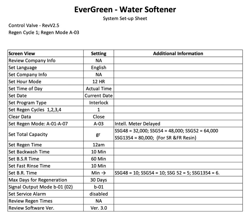
TABLE OF CONTENTS

Product Dimensions & Specifications .......................                         pg. 3
Bypass Instructions .....................................................           pg. 4
Pre-Installation ..............................................................     pg. 5
Operating Conditions & Cautions ...............................                     pg. 6
System Location ...........................................................         pg. 7
Programming .................................................................       pg. 8-10
System Set-up ..............................................................        pg. 10-11
Start-up Instructions ....................................................          pg. 12
Troubleshooting ...........................................................         pg. 13-15
Warranty ........................................................................   pg. 15-16

                                            1206 W. Capitol Drive       sales@pargreen.com
                                            Addison, IL 60101           www.pargreenwater.com
                                            800-323-2810
Product Dimensions and Specifications

               Length (max.)                 Width (max.)           Height (max.)       Regeneration Mode
                     8"                            8"                    6.10"              Down-flow
       These valve dimensions are for reference only.

Connect Port Dimensions
Product Model Inlet Port Outlet Port Drain Port             Brine Port   Base        Riser Pipe   Hard Water Bypass
   RevV2.5           1"            1"    1/2" Barb              3/8"      2.5" 8NPSM    1.05"           Yes
 Main Technical Parameters
 Water Capacity See Performance Data Sheet
 Power Input          120VAC / 60Hz
 Power Output         12VAC / 1.5A
                 Sequence 1: Service → Backwash → Brine & Slow Rinse → Fast Rinse → Brine Refill
Regeneration     Sequence 2: Service → Backwash → Brine & Slow Rinse → Backwash → Fast Rinse → Brine Refill
Cycles           Sequence 3: Service → Brine Refill → Service (240 min-time fixed) → Backwash → Brine & Slow Rinse
                 → Backwash → Fast Rinse
                 Sequence 4: Service → Backwash → Fast Rinse → Air Draw

                                                                                                             3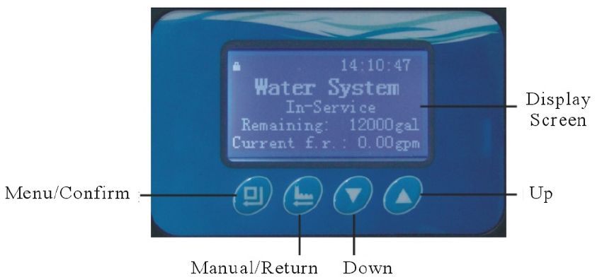
Bypass Installation

∗    Push Pull Bypass – 41204 NA / Every EverGreen System uses a Ceramic Bypass -- 41205
     Note: Before attaching the bypass to the valve, verify the meter is installed into the outlet side of the bypass with the
     impeller facing in.
        As Figure 1-2 shows; install the seals into the animated connector.
        Attach animated connectors to the inlet/outlet and grease the O-rings.
        Attach the bypass valve and insert the clips.
        Meter cable is installed into cable port on the outlet side during system start-up, see page 25.

                                                                                            EverGreen uses the Ceramic
                                                                                                 Upgrade By-Pass

                                                       Figure 1-2

                                                                                                                     4
Pre-Installation Checklist

   IMPORTANT NOTICE

   Read through the instructions thoroughly and obtain all materials and tools before proceeding with the
   installation. Be sure to follow all applicable national, state, county and local plumbing codes and regulations.

   All plumbing and electrical work should be performed by an accredited professional to ensure all local, state,
   and municipal guidelines are met.

   During cold weather it is recommended that the installer warm the valve to room temperature before
   operating.

   Required Operating Conditions

                               Working Pressure                20psi to 90psi
    Working Conditions
                               Water Temperature               35 °F to 125 °F
                               Environment Temperature 35 °F to 125 °F
    Working Environment Relative Humidity                      ≤95%

                               Power Source                    120VAC /60Hz

                               Turbidity                         5 FTU
                               Hardness                        50 grains per gallon
    Inlet Water Quality
                               Chlorine                          1.0 ppm

                               Iron                              1.0 ppm

                                                               <
                                              CAUTION
                                                    <
                                   Do not exceed 120 psi water pressure.
                               Do not exceed 35° C / 125° F water temperature.
                                  Do not subject unit to freezing conditions.

              Failure to use this product within the described conditions may void the warranty.

                                                                                                                5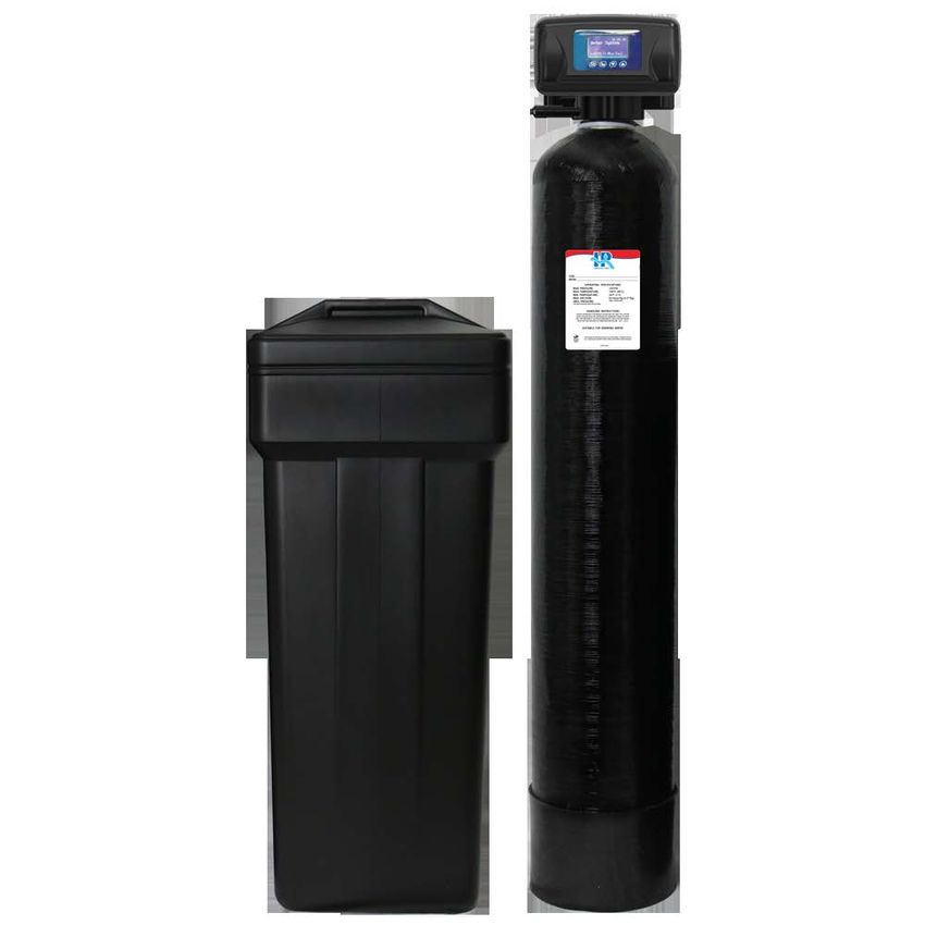
Operating Condition and Cautions

•   Do not use the system with water that is microbiologically unsafe or of unknown quality without
    adequate disinfection before or after the system.

•   Do not use the brine tube, injector body, or other connectors on the RevV2.5 valve as a handle to carry
    the system.

•   Ensure there is salt in the brine tank at all times when this valve is used for softening. The brine tank
    should contain clean water softening salt only, at least 99.5% pure. Do not use small grain salt.

•   When there is moderate to high turbidity, a filter should be installed before the water softening system
    on the inlet side.

•   If the water pressure exceeds 120psi, a pressure reducing valve must be installed before the water inlet. If
    the water pressure exceeds 80 psi, installing a pressure reducing valve before the water inlet is highly
    recommended. If the water pressure is under 20 psi, a booster pump must be installed before the
    water inlet.

•   Replacement parts for the ApsenPro valve should only be purchased through Pargreen
    resellers. Electrical components, such as transformers, are specific to the AspenPro valve from Pargreen.

•   Regular interval monitoring of the water quality and work environment is recommended to ensure
    proper operation of the valve and system.

•   Any modification to AspenPro equipment, which is outside the standard scope of supply, voids
    the product warranty.

•   AspenPro equipment, like all modern electronic devices, can be damaged by electrical surges or
    brown outs. Every effort has been taken to harden the circuits, by design, to protect against such
    events. These precautions, or even additional surge protection, are not 100% effective. Therefore,
    equipment damage caused by abnormal electrical events is not covered by warranty.

Plumbing and Mechanical Setup
If making a soldered copper installation, all sweat soldering should be done before connecting pipes to the
valve. Torch heat will damage plastic parts.

When turning threaded pipe fittings onto plastic fitting, take precaution not to cross thread or over tighten.

                                                                                                            6
Unit Location

•   The filter or softener should be located close to a floor drain away from direct sunlight and any heat
    sources.

•   Protect equipment from direct sunlight and precipitation exposure.

•   Install equipment in a location safe from unauthorized access or vandalism.

•   Ensure that the unit is installed with enough space for operation and maintenance.

•   The installation surface should be clean and level.

•   Install the unit in an environment which minimizes consumer risk of loss in the event of malfunction.

•   AspenPro offers many different products for many different applications, for both indoor and
    outdoor environments. If you are not 100% sure the equipment purchased is suitable for the
    installation application or environment, please check with a your local equipment provider, to ensure
    the proper equipment is selected. Equipment installed in inappropriate applications or environments
    are not covered by warranty.

•   Brine tank should be installed within 10 feet of the AspenPro control valve.

                                                                                                             7
Programming: Display and Instructions

                                                                       Display Screen

  Menu/Confirm                                                         Up

                            Back/Return/ Down
                            Manual Regeneration

  Unlocking the Keypad
  The      icon indicates the buttons are locked within 5 minutes of idle use. To unlock press and hold   and
  for 3 seconds until the     icon is off.

  Manual / Delayed Regeneration
  1. Pressing     at any time results in an immediate manual regeneration.
  2. Pressing and holding      for 3 seconds, when system is locked, results in a delayed regeneration at the
     preselected time.

  One Button to Change the Current Time
  Pressing and holding the   button for 3 seconds, when system is locked, allows the current time of day to
  be adjusted.

                                                                                                          8
Enter Key
Press button to enter the basic programming mode, modify highlighted options, and return to the main
menu.
Manual Regen/Esc. Key
Press
to the home screen without modifying the current highlighted option.
at any phase during manual regeneration to advance to the next phase or press during programming to exit
Up and Down Arrows
and buttons are used to scroll through the various basic programming options as well as adjust values.
Basic Programming
Allows you to adjust the time values for each phase. To enter basic programming, follow the directions below.
1. When the icon is on, press and hold both and for 3 seconds to unlock the keypad.
2. Press to enter the main menu; press or to highlight each option.
3. Press to enter highlighted option.
4. Press or to adjust the value.
5. Press to accept changes.
6. Press to exit back to service status.
Advanced Programming
Allows you to set the Regen Cycle and Regen Mode that will work best for your customer; as well as adjust or
set each phase time. To enter advanced programming, follow the directions below.
91. Plug in the RevV2.5. Immediately press in sequence to enter into the advanced setting.
2. Press or to select the menu item to be changed.
3. Press to return to the previous menu.
If valve locks while programming, unplug power supply and repeat step above.
4. Press to enter the main menu; press or to highlight each option.
5. Press to enter highlighted option.
6. Press or to adjust the value.
7. Press to accept changes.
8. Press to advance to service status.
AspenPro Water Softener
1011
Start-up Instructions – Water Conditioners (Softeners & Filters)
1. Plugging in the power cord: Plug the water conditioner's transformer into an
   appropriate electrical outlet. Then plug the DC jack into the pigtail cord on the control
   (see manual.)

    Make sure that the outlet is not on a switch. The outlet needs to be live at all times.
    Avoid electrical circuits that also service large appliances, sump pumps or devices with
    large motors with high Amp draw.
2. Ensure that the water heater supply valve is off during the conditioner start-up!

3. Setting the water conditioner controls: Set the controller as directed in the manual.
   For a Water Softener: Set time and date, water hardness and number of people supplied
   by the system. For a Filter: Set time and date.
4. Open the bypass valve: It is recommended to keep the water inlet valve at ½ open
   during the next step. With the control set for normal service, slowly open the water inlet
   valve and check for leaks in the installation plumbing. If okay, slowly open the bypass
   valve.
5. Allow water to fill the conditioner tank. Run the water into the conditioner until the
   flow stops.
6. Perform a conditoioner regeneration cycle. Follow the instructions in this manual for a
   “manual regeneration” start-up. (see pg. 8)
   VERY IMPORTANT: TURN THE WATER INLET TO THE “OFF” POSITION BEFORE
   STARTING STEP 6. PUT TWO GALLONS OF CLEAN WATER IN THE SALT TANK
   BEFORE STARTING THE MANUAL REGENERATION CYCLE.

    Note: There will be air trapped in the top of the conditioner tank at the beginning of this
    step. Make sure the drain hose is secured before starting the manual regeneration.
    Once the control is in its first cycle, slowly open the water inlet (about ¼ open) and allow
    the air to escape to the drain. When the air has cleared the conditioner, turn the water
    inlet to full and allow the conditioner to finish the complete regeneration cycle.
    In the case of a filter conditioner, check the drain water during the fast rinse to see
    that all the media fines & color are cleared. If color remains, run the cold faucet
    nearest to the conditioner until the water is clear.
7. Water softener salt and salt tank. Make sure the water in the salt tank is above the
   salt grid after the systems refills. On the initial start-up, only fill the salt tank half full of
   salt incase adjustments to water levels are required. Use a salt that is 99% pure, solar
   salt crystals are recommended.
8. Water Heater. Open the water heater supply valve. If the water heater holds hard
   water, it will take several days of service until the hot water is totally soft.

                                                                                                    12
Troubleshooting
Control Valve
Problem Cause Correction
A. Electrical service to unit has been A. Check for consistent electrical service.
interrupted. B. Reset regeneration cycles.
1. Softener fails
B. Regeneration cycles set incorrectly. C. Replace controller.
to regenerate
C. Controller is defective. D. Replace motor.
D. Motor failure.
2. Regeneration A. Time of Day not set correctly. Check program and reset time of day.
time is not B. Power failure over 3 days.
correct
A. Bypass valve is open or leaking. A. Close or repair bypass valve.
B. No salt in brine tank. B. Add salt to brine tank and maintain salt level above water
C. Injector plugged. level.
D. Insufficient water level in brine tank. C. Change or clean injector.
E. Leak at O-ring on riser pipe. D. Check brine tank refill time.
3. Hard water F. Internal valve leak. E. Make sure riser pipe is not cracked. Check O-ring and tube
G. Regeneration cycles not correct. pilot.
H. Shortage of resin. F. Change valve body.
I. Bad quality of feed water or meter blocked. G. Set correct regeneration cycles in the program.
H. Add resin to mineral tank and check for leaks.
I. Reduce the inlet turbidity, clean or replace meter.
A. Line pressure is too low. A. Increase line pressure.
B. Brine line is plugged. B. Clean brine line.
C. Brine line is leaking. C. Replace brine line.
4. Softener fails
D. Injector is plugged. D. Clean or replace injector.
to draw brine
E. Internal leakage. E. Replace valve body.
F. Drain line is plugged. F. Clean drain line flow control.
G. Wrong size BLFC, DLFC and injector. G. Install properly sized BLFC, DLFC and injector. See Page 13.
5. Unit uses too A. Improper salt setting. (Brine refill time) A. Check salt usage and salt setting. (Brine refill time)
much salt B. Excessive water in brine tank. B. See problem no.6.
A. Brine refill time is too long. A. Reset correct refilling time.
B. Foreign material in brine line. B. Clean brine line.
6. Excessive
C. Foreign material in brine valve or plugged C. Clean brine valve, and DLFC.
water in brine
drain line flow control. D. Put the valve in bypass. Install a safety float in brine tank.
tank
D. Power outage during brine fill. E. Repair or replace brine safety valve.
E. Safety valve in brine tank malfunction.
13A. Iron in the water supply pipes. A. Clean the water supply pipe.
7. Pressure lost B. Iron mass in the softener. B. Clean valve and add resin cleaning chemical, increase
or iron in C. Fouled resin bed. frequency of regeneration.
conditioned D. Too much iron in the raw water. C. Check backwash, brine draw and brine refill. Increase
water frequency of regeneration and backwash time.
D. Install Iron removal equipment before softening.
A. Air in water system. A. Assure that well system has proper air eliminator control.
8. Loss of
B. Bottom strainer broken. B. Replace bottom strainer.
mineral through
C. Improperly sized drain line control (DLFC). C. Check for proper drain rate.
drain line
A. Signal to the locating PCB is interrupted. A. Check the connection between the main PCB to the
9. Control B. Controller is faulty. locating PCB.
cycles C. Foreign material in the drive gear. B. Replace controller.
continuously D. Time of regeneration steps were set to C. Remove blockage in drive gear.
zero. D. Check program setting and reset.
A. Internal valve leak. A. Check and repair valve body or replace it.
10. Drain flows
B. Interrupted power supply during B. Adjust valve to service position or turn off bypass valve
continuously
backwash. and restart when power is restored.
A. Water pressure too low or not stable. A. Increase water pressure.
11. Interrupted
B. Injector is plugged or faulty. B. Clean or replace injector.
or irregular
C. Air in resin tank. C. Check and find the reason.
brine
12. Water flows A. Foreign material in the valve body. A. Clean foreign material in valve body.
from drain or B. Hard water mixed in valve body. B. Change valve core or sealing ring.
brine line after C. Water pressure is too high. C. Reduce water pressure or use pressure release function.
regeneration
13. High A. Foreign material in injector. A. Clean and repair injector.
concentration B. Brine valve cannot be shut-off. B. Replace brine valve or clean it.
of brine C. Rapid rinse time is too short. C. Extend rapid rinse time.
A. Regeneration is not occurring. A. Reset regeneration parameters.
B. Fouled resin bed. B. Increase backwash flow rate and time, clean or change
C. Safety float is not at the proper height or resin.
14. Decreased
brine time is low. C. Adjust brine draw time and float height.
Capacity
D. Softener setting not proper. D. Re-test the water and change the valve parameters.
E. Raw water quality has altered. E. Regenerate unit manually then reset regeneration cycle.
F. Flow meter is slow or stationary. F. Disassemble and clean flow meter or replace.
15. Power A. System locked in current phase/cycle. A. Close the bypass until power resumes. If power outage
Outage Occurs lasts over 72 hours, the time of day will need to be reset.
During
Regeneration
14Electronics
Problem Cause Correction
A. Wiring to the front panel is loose. A. Check and replace the wiring.
1. Abnormal B. Control board is faulty. B. Replace control board.
display C. Transformer malfunction. C. Check and replace transformer.
D. Electrical service unstable. D. Verify power source.
A. Wiring to the front panel is loose. A. Check and replace wiring.
B. Front panel damaged. B. Replace front panel.
2. Blank display
C. Control board damaged. C. Replace control board.
D. Electricity is interrupted. D. Check power source.
A. Wiring of locating board with controller A. Replace wiring.
fails to work. B. Replace locating board.
B. Locating board damaged. C. Replace Discs or drive gear.
3. E1 code C. Mechanical drive failure. D. Replace control board.
D. Faulty control board. E. Replace wiring.
E. Wiring to the motor has a short. F. Replace motor.
F. Motor damaged.
A. Hall effect on locating board damaged. A. Replace locating board.
B. Possible short in the wiring to the locating B. Replace wiring.
4. E2 code
board. C. Replace control board.
C. Control board malfunction.
5. E3 or E4 code A. Control board malfunction. A. Replace control board.
15Any parts used for replacement are warrantied for the remainder of the original warranty period applicable to
the part from the date of manufacture so long as the parts are installed by a Pargreen factory trained
and authorized installer.
Hankscraft Runxin's obligation by this Limited Warranty, at is option, is to repair or replace any
warrantied product only. Labor for repair or replacement is not included as part of this warranty. Prior
to returning the product to Pargreen, a valid return materials authorization number must be obtained from
Pargreen. Any product returned to Pargreen without a valid return authorization number will be rejected. Any
product found to be defective will, at the sole discretion of Pargreen, be repaired or replaced. Pargreen
is not responsible for shipping cost to the repair facility. This section lists the sole remedies for any valid
warranty claim.
This warranty does not apply to defects reported to outside of the warranty period.
This warranty does not apply to defects caused by installing, operating, servicing, modifying,
repairing or maintaining (or lack of maintaining) the product outside of Pargreen's
recommendations. Filters, membrane elements and flow restrictors that become fouled or plugged due to
excessive turbidity, dissolved solids, or microorganisms are not covered by this warranty. This warranty does
not apply to defects caused by damage during shipment, neglect, misuse, modification, accident,
noncompliance with local codes and ordinances, hot water, frozen water, sediment, corrosive liquids,
gases, chemicals, bacteria, animals, sand, salt, flood, wind, fire, outdoor installations where the
product is not reasonably covered, pneumatic use, natural disasters, war, terrorism or acts of God. No
other person is authorized to make any other warranty on behalf of Pargreen either during or after the
applicable warranty period.
Pargreen assumes no liability for determining the proper products and equipment
or installation necessary to meet the requirements of the user of the product, and Pargreen does
not authorize others to assume such liability on its behalf.
THE WARRANTIES AND REMEDIES HEREIN ARE EXCLUSIVE AND IN LIEU OF ANY AND
ALL OTHER WARRANTIES OR REMEDIES EITHER EXPRESSED OR IMPLIED, HEREIN OR
ELSEWHERE, INCLUDING WITHOUT LIMITATION WARRANTIES OF MERCHANTABILITY, FITNESS
FOR ANY PARTICULAR PURPOSE, NON-INFRINGEMENT OR WARRANTIES RESULTING FROM
COURSE OF PERFORMANCE, COURSE OF DEALING OR FROM USAGE OF TRADE.
HANKSCRAFT RUNXIN HEREBY DISCLAIMS ALL OTHER WARRANTIES. HANKSCRAFT
RUNXIN'S LIABILITY SHALL NOT EXCEED THE COST OF THE PRODUCT AND IS NOT
RESPONSIBLE FOR INCIDENTAL OR CONSEQUENTIAL DAMAGES OR EXPENSES OF ANY
KIND WHATSOEVER, INCLUDING LOSS OF PROFITS, UNDER ANY CIRCUMSTANCES AND
REGARDLESS OF WHETHER HANKSCRAFT RUNXIN WAS AWARE OF THE POSSIBILITY OF ANY
SUCH LOSS.
16You can also read