Beam-colored Sketch and Image-based 3D Continuous Wireframe Reconstruction with different Materials and Cross-Sections
←
→
Page content transcription
If your browser does not render page correctly, please read the page content below
Beam-colored Sketch and Image-based 3D Continuous Wireframe Reconstruction with different Materials and Cross-Sections Martin Denk, Klemens Rother, Kristin Paetzold The automated reverse engineering of wireframes is a common task in topology optimiza- tion, fast concept design, bionic and point cloud reconstruction. This article deals with the usage of skeleton-based reconstruction of sketches in 2D images. The result leads to a flex- ible at least ܥଵ continuous shape description. Keywords: Reverse Engineering, Fast Concept Design, Skeleton Introduction Modern design projects with complex problems are often decomposed, and each part is tackled by a multidisciplinary design team (MDT) (Ensici and Badke-Schaub, 2011). Splitting the development into different parts is the simplest decision but comes with a high risk of a suboptimal solution (Song, 2004). In particular, in the early stage of product development, fast concept design is required, which should ensure a huge amount of conceptual design suggestions. With a huge number of simple sketches, the rough shape of the product is often estimated but not evaluated. Particularly, in mod- ern lightweight designs, shapes derived from scanned point clouds (Berger et al., 2017) or from surfaces in finite element analysis (Ben Makhlouf et al., 2019; Louhichi et al., 2015) are necessary to redesign. Such shape is often computed numerically using structural optimization such as topology optimization (Changizi and Warn, 2020; Denk et al., 2020a), shape optimization (Bandara et al., 2016), or in some cases, multi-mate- rial optimization (Gao et al., 2020). For the reconstruction, a huge variety of different shape descriptor (Agathos et al., 2007; Guo et al., 2016) can be chosen, such as con- structive solid geometry (CSG) (Bénière et al., 2013; Denk et al., 2019; Vidal et al., 2014) or freeform surfaces representing the boundary (Ben Makhlouf et al., 2019; Louhichi et al., 2015). In particular organic shapes resulting from topology optimization, a de- scriptor such as medial axes (skeletons) (Blum, 1967) shows desirable concepts for re- cent reverse engineering approaches in topology optimization (Mayer and Wartzack, 2020; Nana et al., 2017a; Stangl and Wartzack, 2015; Yin et al., 2020). These skeleton- Beam-colored Sketch and Image-based 3D Continuous Wireframe Reconstruction with different Materials and Cross-Sections 345
based methods are capable of reasonable part segmentation (Agathos et al., 2007;
Feng et al., 2015; Reniers and Telea, 2008), so that a hand can be segmented into five
fingers and the palm of the hand (Wu et al., 2016). Such parametrization has been
implemented in various applications for the reverse engineering task in topology opti-
mization (Mayer and Wartzack, 2020; Nana et al., 2017a; Stangl and Wartzack, 2015;
Yin et al., 2020) for predefined optimized shapes. Performing topology optimization
requires knowledge in finite element analysis, mechanical engineering and access to
software packages. Additionally, these results often need to be modified to fulfill geo-
metric limitations for the manufacturing process such as 3D printing (Adam and Zim-
mer, 2015). The approach proposed in this article deals with a fast concept design us-
ing images that can result from topology optimization, hand-drawn sketches, or com-
puter-aided design applications. If proof of strength or further shape optimization
should be done, such shapes can directly be evaluated with a small amount of
knowledge in mechanical engineering.

State of the Art
State of the Art is referred to skeleton-based reverse engineering and sketch-based
reverse engineering strategies. Sketch-based reverse engineering deals with the 3D
shape reconstruction using 2D sketches (Zhao et al., 2017). In the recent publications,
the beamline of topology optimized shapes is approximated by a contraction method
applied on a polygon mesh (Nana et al., 2017b; Stangl and Wartzack, 2015), a medial
axis transformation (Mayer and Wartzack, 2020), or morphological thinning applied on
images (Bremicker et al., 1991; Denk et al., 2020b; Yin et al., 2020). While these publi-
cations cover only the geometric shape, our approach also deals with different mate-
rials, predefined cross-sections, and, similar to (Denk et al., 2020b), a fully automated
robust subdivision surface representation. Additionally, the use-cases are extended to
also user-defined shapes for 2D images. Furthermore, we use similar to (Zhao et al.,
2017) skeleton-based sketches for the reconstruction, which is extended using colored
regions in the image similar to (Xu et al., 2013). Our work is mostly inspired by our
recent work (Denk et al., 2020b). In that approach, shapes, as obtained by topology
optimization, are reconstructed to a subdivision surface control grid by using the Eu-
clidian distance transformation for circular control grids. In contrast, this work ad-
dresses the usage of different materials and automatic beam evaluation with a finite
element method and also considering elliptical cross-sections. The following figure
shows the fast concept design using colored cross-sections and the line thickness of a
skeleton and its desirable 3D parametrization.

346                                                           Martin Denk, Klemens Rother, Kristin Paetzold
Skeleton          Colored Skeleton                            „Skin“ of the Skeleton                         Shape Adjustment
 (Line Thickness)      (Cross Sections)                            (Subdivision Surfaces)

                                           Figure 1: Coloured Shape Determination

Sketch-based reconstruction
As input, the user has to draw a skeleton-based sketch with optional colored lines and
corresponding colored cross-sections. Based on the cross-section bounding box, we
estimate the shape using subdivision surfaces and evaluate the suggested concept au-
tomatically using FEM. These subdivision surfaces are bounded by the skeleton so that
adjusting the position of the skeleton knots also changes the resulting surface. To gen-
erate a wire frame representation, these images need to be transferred into
wireframes enriched by the corresponding cross-sections. First, the extraction of the
skeleton similar to (Denk et al., 2020b) is covered In the following chapters. The image
is thinned until a beam-like representation consists. Second, based on the line thick-
ness or the colored cross-section, the finite element analysis and the subdivision sur-
face control grid estimation are covered. This beam representation serves for the 3D
redesign.
Beam Line Approximation Using Thinning and B-Spline Fitting
The skeleton is approximated by applying a homotopic thinning method (Lee et al.,
1994). The pixels of the image will be iteratively eroded until a chain having only one-
pixel in thickness is finally obtained. Based on that skeleton, a topological segmenta-
tion followed by B-spline fitting is applied. The following figure shows the different
steps for the estimation of the beamline topology and its position.
Cross-Section Extraction and FEM
The determination of the cross-section covers two different approaches. First, if no
cross-section is predefined, the line thickness of the skeleton is chosen as an approxi-
mation of the control grid similar to (Denk et al., 2020b). Second, if a predefined ellip-
tical cross-section is chosen, the control grid is approximated using a bounding box.
The following figure shows the two different strategies for the determination of the
control grid for the subdivision surface model.

Beam-colored Sketch and Image-based 3D Continuous Wireframe Reconstruction with different Materials and Cross-Sections               347
2D Image 2D Binary
(Coloured)
Binarization
Image
2D Binary
Image
Thinning
Topological Segmented
Segmentation Image
B-Spline Legend
Model B-Spline Fitting
Data Data flow
Object
Control flow
Action
Figure 2: Beam Line Approximation
Distance
Segmentation
Transformatoin
Median Radis of each
Bounding Box
Beam
Parameter
Approximation
ܾ ܾ
ܽ Control Grid
Approximation ܽ ܽ
ܽ ʹݎ
Figure 3: Radii determination
Based on these cross-section properties, a finite-element analysis can be directly ap-
plied to beam elements. The stiffness matrix for a 2D-truss element can be com-
puted by
ͳ ܣ െͳ (1)
ൌ න ் ݀ȳ ൌ ܣන ் ݈݀ ൌ ܧ ቂ ቃǡ
ஐ ݈ െͳ ͳ
where represents the strain-displacement transformation matrix and the material
matrix reducing to the modulus of elasticity ܧ, ܣthe area of the cross-section and ݈ the
length of the element (Rieg et al., 2012). For a 2D-beam element, the stiffness matrix
can be computed with
348 Martin Denk, Klemens Rother, Kristin Paetzold்
ͳʹ ݈ െͳʹ ݈
ଶ
߲ଶ ߲ଶ
ܫ݈ Ͷ݈ ଶ െ݈ ʹ݈ ଶ
ൌ ܧන ܣ݀ ݕන ቆ ଶ ࡺቇ ቆ ଶ ࡺቇ ݀ ݔൌ ܧଷ ൦ ൪ǡ (2)
߲ݔ ߲ݔ ݈ െͳʹ െ݈ ͳʹ െ݈
݈ ʹ݈ ଶ െ݈ Ͷ݈ ଶ
with the second moment of inertia ( ܫRieg et al., 2012). By assembling both stiffness
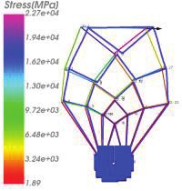
matrices, a complete frame structure can be computed. The following figure shows the
result of a colored sample using FEM. By changing the material properties for the red
lines, the corresponding elements are stiffer so that the deformation is smaller.
ܧൌ ͲͲͲͲ
ܧൌ ͲͲͲͲ
ܧൌ ͲͲͲͲ
ܧൌ ͲͲͲͲ ܧൌ ʹͳͲͲͲͲ
ܧൌ ͲͲͲͲ
Two Overlay Beams (Same Topological Start and Endpoint)
Figure 4: Sample of the topological segmented beam with the young module with F=10000
Subdivision Surface Reconstruction
The figure 5 shows the assembly of the skeleton and control points of the cross-section
into a connected control grid mesh. For each beam along with the skeleton, several
points are chosen where the control grid of the cross-section is applied. These control
girds are connected to a beam control grid, which consists of a not-connected mesh
for each beam. On the junctions, the corresponding control points of the connected
beams are chosen to compute a convex hull. Such hull and the beams are combined
using a Boolean operation on the mesh. This connected mesh can be subdivided for a
smooth geometry.
Skeleton
Cross-Section Beam
Generate Beam
Cotrol Grid Control
Control Points Grid
Hull On Convex Hull On the
Connection Dissconnected
Junctions
Boolean Beam and Connected
Junction Control Grid Mesh
Representation Subdivide
Figure 5: Subdivision Surface Reconstruction of the wireframe model
Beam-colored Sketch and Image-based 3D Continuous Wireframe Reconstruction with different Materials and Cross-Sections 349The figure 6 shows the generation of the control grid of the cross-section by projecting
them normal to the skeleton. Additionally, the generation of the Convex Hull is visual-
ized for a junction.
Cross-Section Grid Convex Hull on Junctions
ܽ
Figure 6: Control Grid Creation for Beams and Junctions
Beam Represen- 3D Model (con-
Use Case Skeleton FEM 1D
tation nected)
Fixed
Table 1: Use-Cases of the wireframe reverse engineering
350 Martin Denk, Klemens Rother, Kristin PaetzoldExperiment
The experiment is separated into two parts. First, the sketch-based reconstruction on
four samples is covered, showing the skeleton, the beam model, the Finite Element
model, and the beams connected to the junctions. Table 1 shows the result using dif-
ferent colored cross-sections, different frame structures, and different line thicknesses.
In particular, the last results derived from Michell structures (M.C.E, 1904) show a ro-
bust approach covering complex shapes and a huge amount of junctions. Additionally,
the figure 7 shows the example using different elliptical cross-sections depending on
the orientation and the size of the designed section. The different sizes of the cross-
section are smoothly connected to each other.
That proposed approach can also be applied to results provided by topology optimiza-
tion. Table 2 covers different use-cases in topology optimization, such as simultaneous
consideration of multiphysics, like a pareto-optimization of linear elastostatics heat
transfer and fluid flow (Denk et al., 2020a).
Table 2: Reverse Engineering of 2D Results in Topology Optimization
Convex Hull con-
Use Case Segmentation Skeleton Beam Grid
nected
Figure 7: Sample showing the connection of different beams as junctions
Beam-colored Sketch and Image-based 3D Continuous Wireframe Reconstruction with different Materials and Cross-Sections 351Conclusion This article deals with the fully automated evaluation and 3D redesign of images cov- ering beam-like shapes. The skeleton-like images can be provided by topology optimi- zation, sketches, or drawing images. Based on the skeleton image, the beamlines are approximated using a thinning method. The cross-sections are determined by the Eu- clidian distance transformation or by predefined elliptical cross-section sketches. These cross-sections serve as a guideline for the control grid estimation for a subdivi- sion surface grid. Based, on this beam representation, a finite element analysis is per- formed. For each topological segmented beam, one element is defined. Based on the color of the skeleton and predefined cross-section, different materials and cross-sec- tions can be covered automatically. The subdivision surface beam grids need to be connected to each other. Therefore, this work uses a convex hull algorithm, which con- nects the control grid of each topological segmented beam on each junction. After- ward, this convex hull on the junction is united with the beam elements so that con- nectivity is ensured. For wireframe sketches, optimized topology results, or Michell structures shown in (M.C.E, 1904), this approach leads to a reasonable result. The topology and each branch are covered but it can sometimes lack in covering the size of cross-sections. Due to the convex hull on each junction, quite a number of polygons are generated, which increases the number of points particular in that region. For further processing, the points on these junctions should be reduced. To cover a better approximation of the beams, a more variable cross-section can be applied along each beam. Literature Adam, G.A.O., Zimmer, D., 2015. On design for additive manufacturing: evaluating geometrical limitations. Rapid Prototyp. J. 21, 662–670. https://doi.org/10.1108/RPJ-06-2013-0060 Agathos, A., Pratikakis, I., Perantonis, S., Sapidis, N., Azariadis, P., 2007. 3D Mesh Segmentation Methodologies for CAD ap- plications. Comput.-Aided Des. Appl. 4, 827–841. https://doi.org/10.1080/16864360.2007.10738515 Bandara, K., Rüberg, T., Cirak, F., 2016. Shape optimisation with multiresolution subdivision surfaces and immersed finite elements. Comput. Methods Appl. Mech. Eng. 300, 510–539. https://doi.org/10.1016/j.cma.2015.11.015 Ben Makhlouf, A., Louhichi, B., Mahjoub, M.A., Deneux, D., 2019. Reconstruction of a CAD model from the deformed mesh using B-spline surfaces. Int. J. Comput. Integr. Manuf. 32, 669–681. https://doi.org/10.1080/0951192X.2019.1599442 Bénière, R., Subsol, G., Gesquière, G., Le Breton, F., Puech, W., 2013. A comprehensive process of reverse engineering from 3D meshes to CAD models. Comput.-Aided Des. 45, 1382–1393. https://doi.org/10.1016/j.cad.2013.06.004 352 Martin Denk, Klemens Rother, Kristin Paetzold
Berger, M., Tagliasacchi, A., Seversky, L.M., Alliez, P., Guennebaud, G., Levine, J.A., Sharf, A., Silva, C.T., 2017. A Survey of Surface Reconstruction from Point Clouds: A Survey of Surface Reconstruction from Point Clouds. Comput. Graph. Forum 36, 301–329. https://doi.org/10.1111/cgf.12802 Blum, H., 1967. A Transformation for Extracting New Descriptors of Shape. M.I.T. Press. Bremicker, M., Chirehdast, M., Kikuchi, N., Papalambros, P.Y., 1991. Integrated Topology and Shape Optimization in Struc- tural Designכ. Mech. Struct. Mach. 19, 551–587. https://doi.org/10.1080/08905459108905156 Changizi, N., Warn, G.P., 2020. Topology optimization of structural systems based on a nonlinear beam finite element model. Struct. Multidiscip. Optim. https://doi.org/10.1007/s00158-020-02636-x Denk, M., Paetzold, K., Rother, K., 2019. Feature line detection of noisy triangulated CSGbased objects using deep learning, in: Proceedings of the 30th Symposium Design for X (DFX 2019), DfX. Presented at the DfX Symposium 2019, The Design Society, Jesteburg, Germany, pp. 239–250. https://doi.org/10.35199/dfx2019.21 Denk, M., Rother, K., Paetzold, K., 2020a. Multi-Objective Topology Optimization of Heat Conduction and Linear Elastostatic using Weighted Global Criteria Method, in: Proceedings of the 31st Symposium Design for X (DFX2020), DFX. Presented at the DfX Symposium 2020, The Design Society, Bamberg, pp. 91–100. https://doi.org/10.35199/dfx2020.10 Denk, M., Rother, K., Paetzold, K., 2020b. Fully Automated Subdivision Surface Parametrization for Topology Optimized Structures and Frame Structures using Euclidean Distance Transformation and Homotopic Thinning, in: Proceedings of the Munich Symposium on Lightweight Design 2020. Springer Nature, Munich, Germany. https://doi.org/10.1007/978-3-662- 63143-0 Ensici, A., Badke-Schaub, P., 2011. Information behavior in multidisciplinary design teams, in: Proceedings of the 18th Inter- national Conference on Engineering Design (ICED 11). Presented at the Proceedings of the 18th International Conference on Engineering Design (ICED 11), Denmark, pp. 414–423. Feng, C., Jalba, A.C., Telea, A.C., 2015. Part-Based Segmentation by Skeleton Cut Space Analysis, in: Benediktsson, J.A., Chanussot, J., Najman, L., Talbot, H. (Eds.), Mathematical Morphology and Its Applications to Signal and Image Processing, Lecture Notes in Computer Science. Springer International Publishing, Cham, pp. 607–618. https://doi.org/10.1007/978-3- 319-18720-4_51 Gao, J., Luo, Z., Xiao, M., Gao, L., Li, P., 2020. A NURBS-based Multi-Material Interpolation (N-MMI) for isogeometric topol- ogy optimization of structures. Appl. Math. Model. 81, 818–843. https://doi.org/10.1016/j.apm.2020.01.006 Guo, Y., Bennamoun, M., Sohel, F., Lu, M., Wan, J., Kwok, N.M., 2016. A Comprehensive Performance Evaluation of 3D Lo- cal Feature Descriptors. Int. J. Comput. Vis. 116, 66–89. https://doi.org/10.1007/s11263-015-0824-y Lee, T.C., Kashyap, R.L., Chu, C.N., 1994. Building Skeleton Models via 3-D Medial Surface Axis Thinning Algorithms. CVGIP Graph. Models Image Process. 56, 462–478. https://doi.org/10.1006/cgip.1994.1042 Louhichi, B., Abenhaim, G.N., Tahan, A.S., 2015. CAD/CAE integration: updating the CAD model after a FEM analysis. Int. J. Adv. Manuf. Technol. 76, 391–400. https://doi.org/10.1007/s00170-014-6248-y Mayer, J., Wartzack, S., 2020. Ermittlung eines Skelettierungsverfahrens zur Konvertierung von Topologieoptimierungsergeb- nissen, in: Proceedings of the 31st Symposium Design for X (DFX2020). Presented at the Symposium Design for X 2020, Bamberg, pp. 111–120. https://doi.org/10.35199/dfx2020.12 Beam-colored Sketch and Image-based 3D Continuous Wireframe Reconstruction with different Materials and Cross-Sections 353
M.C.E, A.G.M.M., 1904. LVIII. The limits of economy of material in frame-structures. Lond. Edinb. Dublin Philos. Mag. J. Sci.
8, 589–597. https://doi.org/10.1080/14786440409463229
Nana, A., Cuillière, J.-C., Francois, V., 2017a. Automatic reconstruction of beam structures from 3D topology optimization
results. Comput. Struct. 189, 62–82. https://doi.org/10.1016/j.compstruc.2017.04.018
Nana, A., Cuillière, J.-C., Francois, V., 2017b. Automatic reconstruction of beam structures from 3D topology optimization
results. Comput. Struct. 189, 62–82. https://doi.org/10.1016/j.compstruc.2017.04.018
Reniers, D., Telea, A., 2008. Part-type Segmentation of Articulated Voxel-Shapes using the Junction Rule. Comput. Graph.
Forum 27, 1845–1852. https://doi.org/10.1111/j.1467-8659.2008.01331.x
Rieg, F., Hackenschmidt, R., Alber-Laukant, B., 2012. Finite Elemente Analyse für Ingenieure, 4., überarbeitete Edition. ed.
Carl Hanser Verlag GmbH & Co. KG, München.
Song, S., 2004. Shared Understanding, Sketching, and Information Seeking and Sharing Behavior in the New Product De-
sign Process. University of California, Berkeley.
Stangl, T., Wartzack, S., 2015. Feature based interpretation and reconstruction of structural topology optimization results, in:
Weber, M., C.;. Husung, S.;. Cascini, G.;. Cantamessa, M.;. Marjanovic, D.;. Bordegoni (Ed.), Proceedings of the 20th Inter-
national Conference on Engineering Design (ICED15). Design Society, p. Vol. 6, 235-245.
Vidal, V., Wolf, C., Dupont, F., 2014. Mechanical Mesh Segmentation and Global 3D Shape Extraction.
Wu, B., Xu, K., Zhou, Y., Xiong, Y., Huang, H., 2016. Skeleton-guided 3D shape distance field metamorphosis. Graph. Mod-
els, SI\: CVM 2016 selected Papers 85, 37–45. https://doi.org/10.1016/j.gmod.2016.03.003
Xu, K., Chen, K., Fu, H., Sun, W.-L., Hu, S.-M., 2013. Sketch2Scene: sketch-based co-retrieval and co-placement of 3D mod-
els. ACM Trans. Graph. 32, 123:1-123:15. https://doi.org/10.1145/2461912.2461968
Yin, G., Xiao, X., Cirak, F., 2020. Topologically robust CAD model generation for structural optimisation. Comput. Methods
Appl. Mech. Eng. 369, 113102. https://doi.org/10.1016/j.cma.2020.113102
Zhao, X., Gregor, R., Mavridis, P., Schreck, T., 2017. Sketch-based 3D Object Retrieval with Skeleton Line Views - Initial Re-
sults and Research Problems. The Eurographics Association. https://doi.org/10.2312/3dor.20171052

Contact
Martin Denk, M. Sc.                                             Prof. Dr.-Ing. Klemens Rother
Prof. Dr.-Ing. Kristin Paetzold                                 Munich University of Applied Science
Bundeswehr University Munich                                    Institute for Material and Building Research
Institute for Technical Product Development                     Lothstraße 64
Werner-Heisenberg-Weg 39                                        80335 München
85577 Neubiberg                                                 sites.hm.edu/imb/
unibw.de/itpe

354                                                                                       Martin Denk, Klemens Rother, Kristin Paetzold
You can also read