Build Your Own Clone Echo Royal Kit Instructions
←
→
Page content transcription
If your browser does not render page correctly, please read the page content below
Build Your Own Clone
                             Echo Royal
                          Kit Instructions
                                       (Rev 1.1)

Warranty:
BYOC, Inc. guarantees that your kit will be complete and that all parts and components
will arrive as described, functioning and free of defect. Soldering, clipping, cutting,
stripping, or using any of the components in any way voids this guarantee. BYOC, INC
guarantees that the instructions for your kit will be free of any majors errors that would
cause you to permanently damage any components in your kit, but does not guarantee
that the instructions will be free of typos or minor errors. BYOC, INC does not
warranty the completed pedal as a whole functioning unit, nor do we warranty any of the
individual parts once they have been used. If you have a component that is used, but feel
it was defective prior to you using it, we reserve the right to determine whether or not the
component was faulty upon arrival. Please direct all warranty issues to:
sales@buildyourownclone.com This would include any missing parts issues.

Return:
BYOC, Inc. accepts returns and exchanges on all products for any reason, as long as they
are unused. We do not accept partial kit returns. Returns and exchanges are for the full
purchase price less the cost of shipping and/or any promotional pricing. Return shipping
is the customer’s responsibility. This responsibility not only includes the cost of
shipping, but accountability of deliver as well. Please contact
sales@buildyourownclone.com to receive a return authorization before mailing.
Tech Support:
BYOC, Inc. makes no promises or guarantees that you will successfully complete your
kit in a satisfactory manor. Nor does BYOC, Inc. promise or guarantee that you will

                                                                                           1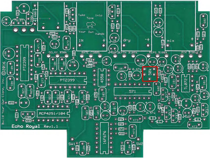
receive any technical support. Purchasing a product from BYOC, Inc. does not entitle
you to any amount of technical support. BYOC, Inc. does not promise or guarantee that
any technical support you may receive will be able to resolve any or all issues you may
be experiencing.

That being said, we will do our best to help you as much as we can. Our philosophy at
BYOC is that we will help you only as much as you are willing to help yourself. We
have a wonderful and friendly DIY discussion forum with an entire section devoted to the
technical support and modifications of BYOC kits.

www.byocelectronics.com/board

When posting a tech support thread on the BYOC forum, please post it in the correct
lounge, and please title your thread appropriately. If everyone titles their threads
“HELP!” then it makes it impossible for the people who are helping you to keep track of
your progress. A very brief description of your specific problem will do. It will also
make it easier to see if someone else is having or has had the same problem as you. The
question you are about to ask may already be answered. Here is a list of things that you
should include in the body of your tech support thread:
1. A detailed explanation of what the problem is. (more than, “It doesn’t work, help”)
2. Pic of the topside of your PCB.
3. Pic of the underside of your PCB.
4. Pic that clearly shows your footswitch/jack wiring and the wires going to the PCB
5. A pic that clearly shows your wiring going from the PCB to the pots and any other
switches (only if your kit has non-PC mounted pots and switches)
6. Is bypass working?
7. Does the LED come on?
8. If you answered yes to 6 and 7, what does the pedal do when it is in the "on" position?
9. Battery or adapter (if battery, is it good? If adapter, what type?)

Also, please only post photos that are in focus.

REV NOTES:

REV 1.1 - Fixed screenprint issues. Includes replacement values for better operation.

Copyrights:
All material in this document is copyrighted 2019 by BYOC, Inc.

                                                                                             2
Echo Royal
                   Kit Instruction Index

Parts Checklist----------------------------------------------page 5-6

Populating the Circuit Board----------------------------page 8-15

Main PCB Assembly---------------------------------------page 16-21

Wiring---------------------------------------------------------page 22-24

Operation Overview----------------------------------------page 25-26

Schematic-----------------------------------------------------page 28

                                                                            3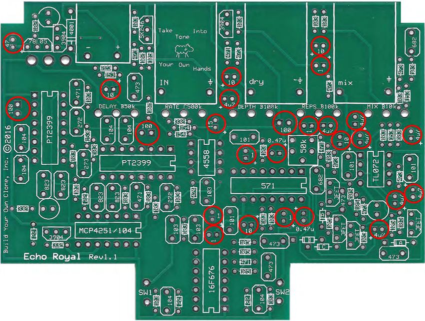
This is what your kit should look like when it’s complete. Your kit may come with
different color capacitors, switches ect. Don’t be alarmed by this. They all still do
                                the exact same thing.

                                                                                        4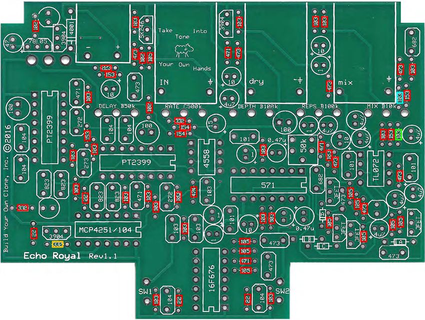
Parts Checklist for the Echo Royal Kit
Resistors: (Metal Film (5 Bands) / Carbon Film (4 Bands))
4 - 22R/22     (Red/Red/Black/Gold/Brown) / (Red/Red/Black/Brown)
3 - 470R/471 (Yellow/Purple/Black/Black/Brown) / (Yellow/Purple/Brown/Gold)
3 - 1k/102     (Brown/Black/Black/Brown/Brown) / (Brown/Black/Red/Gold)
3 - 3k3/332    (Orange/Orange/Black/Brown/Brown) / (Orange/Orange/Red/ Gold)
1 - 4k7/472    (Yellow/Purple/Black/Brown/Brown) / (Yellow/Purple/Red/Gold)
21 - 10k/103 (Brown/Black/Black/Red/Brown) / (Brown/Black/Orange/ Gold)
1 - 12k/123    (Brown/Red/Black/Red/Brown) / (Brown/Red/Orange/Gold)
4 - 15k/153    (Brown/Green/Black/Red/Brown) / (Brown/Green/Orange/ Gold)
1 - 18k/183    (Brown/Gray/Black/Red/Brown) / (Brown/Gray/Orange/Gold)
1 - 22k/223    (Red/Red/Black/Red/Brown) / (Red/Red/Orange/ Gold)
7 - 47k/473    (Yellow/Purple/Black/Red/Brown) / (Yellow/Purple/Orange/ Gold)
2 - 150k/154 (Brown/Green/Black/Orange/Brown) / (Brown/Green/Yellow/ Gold)
1 - 470k/474 (Yellow/Purple/Black/Orange/Brown) / (Yellow/Purple/Yellow/ Gold)
10 - 1M/105    (Brown/Black/Black/Yellow/Brown) / (Brown/Black/Green/ Gold)

Visit www.byocelectronics.com/resistorcodes.pdf for more information on how to
differentiate resistors.

Capacitors:
4 - 100p ceramic disc cap (may say “101” on the body)
2 - 470p ceramic disc cap (may say “471” on the body
2 - .0027u/2n7 film cap (may say “272” on the body)
2 - .0068u/6n8 film cap (may say “682” on the body)
3 - .01u/10n film cap (may say “103” on the body)
1 - .027u/27n film cap (may say “273” on the body)
4 - .047u/47n film cap (may say “473” on the body)
4 - .082u/82n film cap (may say “823” on the body)
6 - .1u/100n film cap (may say “104” on the body)
1 - .47u/470n film cap (may say ‘474’ on the body)
2 - .47uf Aluminum Electrolytic
6 - 1uf Aluminum Electrolytic
8 - 4.7uf Aluminum Electrolytic
5 - 10uf Aluminum Electrolytic
1 - 15uf Aluminum Electrolytic
1 - 47uf Aluminum Electrolytic
3 - 100uf Aluminum Electrolytic

Visit www.byocelectronics.com/capcodes.pdf for more info on how to differentiate
capacitors.

Diodes:
1 - 1N4001 diode
4 - 1N4148 diodes

IC's:
1 - TL072
1 - 4558
1 - 571
2 - PT2399
1 - MCP4251/104
1 - 16F688 or 16F684

                                                                                   5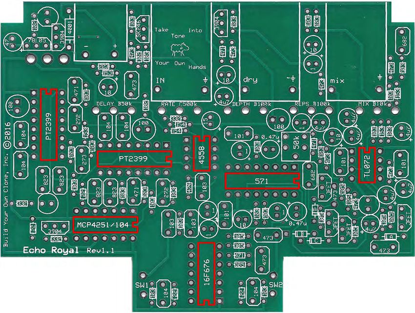
2 - DIP8 sockets
2 - DIP14 sockets
3 - DIP16 sockets

Transistors:
1 - 78L05
3 - 2N3904
4 - 2N5457 (or 2N5458, J111, J112, J113)
1 - 2SK246

Potentiometers: SNAP OFF THE SMALL TABS ON THE TOP OF THE POTS OFF WITH A
PAIR OF NEEDLE NOSE PLIERS. IF YOUR POTS HAVE COVERS, REMOVE THEM BEFORE
CONTINUING. YOU MIGHT HAVE TO CUT A SLIT IN THE COVER WITH A BLADE AND
USE A SMALL SCREWDRIVER TO GET LEVERAGE.

1 - B10k MIX
1 - B50k DELAY
1 - B50k Solder Lug TAP MULTIPLIER
2 - B100k DEPTH, REPS
1 - C500k RATE
1 - 50k Trimpot

Hardware:
1 - predrilled enclosure w/ 4 screws
1 - Echo Royal Printed Circuit Board
2 - momentary footswitch
3 - Enclosed jacks
4 – rubber bumpers
3 – lock washers (for in and out jacks)
hook-up wire
  Your kit will come with mostly 1/8 watt resistors. If you receive ¼ watt resistors,
    simply bend them so the body is vertical on the PCB. Below is an example

                                                                                        6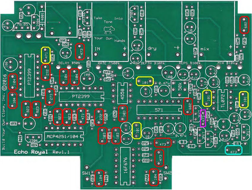
7
Populating the Circuit Board
                                  Replacement Values:
                                   GREEN - R18: 12k
                                    BLUE - R22: 18k
                                  ORANGE - R42: 4k7
Step 1: Add all the resistors. Resistors are not polarized and can be inserted into the PCB
in either direction, meaning you don’t have to worry about orienting them.

                                                                                         8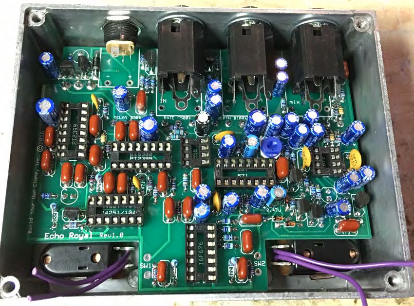
Step 2: Add the diodes. Be sure to match the end of the diode with the stripe
to the layout on the PCB. The striped end should go in the square solder pad.

                                                                                9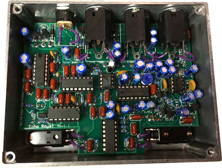
Step 3: Add the IC sockets. Be sure to align the notch on the IC sockets with the notch on
                                  the PCB screenprint.

                                                                                       10
Step 4: Add the transistors. Be sure to match the flat side of the transistor with the flat
side of the transistor on PCB layout. Red outline is 2N3904, blue outline is 78L05, green
outline is 2SK246, and the yellow outline is for the JFETs.
11Step 5: Add the film and ceramic disc capacitors. These are non-polarized so they can go
in either direction. The ceramic disc capacitors are highlighted in yellow, and are also
non-polarized. The “473” highlighted in pink is a .047 film cap and will go on the
underside of the PCB. The capacitor highlighted in BLUE is the .47(474) capacitor.
C8 changed from a .047uF to a .47uF. This adds a very very short rise time to the
switching JFET that lets signal into the delay chips. If you have grounding issues,
the .047uF comes on too quickly and can make a pop that will echo. The .47uF
eliminates this completely no matter what your grounding situation is like.
12When placing the .047uF film capacitor on the underside of the PCB, bend it so it
lies as flat as you can on the PCB. It is recommended to bend the capacitor away
from the LED hole as shown below.
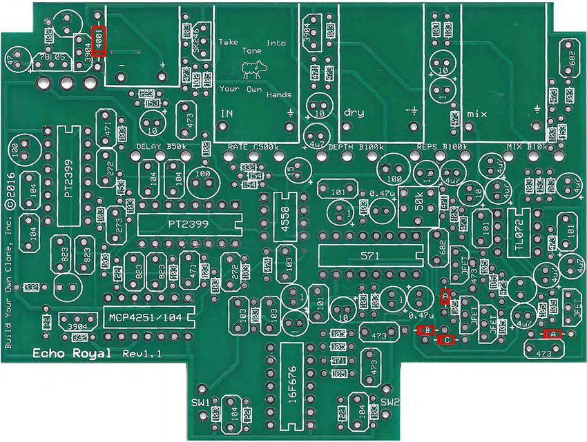
13Step 6: Add the trimpot. This limits the amount of repeats. Most people what to set this
so that the repeats eventually fade away after 10 seconds or so when the repeats knob is
full turn clockwise. If you want infinite repeats, turn this trimpot up a little more. If you
want self-oscillation (when the repeats runaway and keep getting louder) turn it up even
more. You’ll need to set this trimpot when you’re all done building and you actually plug
the pedal in for the first time.
14Step 7: Add the aluminum electrolytic capacitors. These ARE polarized, meaning there
is a positive and negative end. The positive side will have a longer lead and goes in the
square solder pad. The negative side will have a shorter lead and a stripe running along
the body of the cap, and goes in the round solder pad.
15Main PCB Assembly
Step 1: Prepare the footswitches. Cut four 2 inch pieces of wire and solder
them to the footswitches as shown.
16Step 2: Install the footswitches in the enclosure. Orient the footswitches so
the solder lugs are facing each other
17Step 3: Flip the PCB over so that the bottom or solder side is up. Insert the
potentiometers, toggle switch, and the LEDs into the bottom side of the
PCB. IF YOUR POTS HAVE COVERS, REMOVE THEM BEFORE
CONTINUING. YOU MIGHT HAVE TO CUT A SLIT IN THE COVER
WITH A BLADE AND USE A SMALL SCREWDRIVER TO GET
LEVERAGE. DO NOT SOLDER ANYTHING YET!!!
The LEDs will have one lead that is longer than the other. THIS WILL GO
INTO THE SQUARE SOLDER HOLE.
Originally, the Division control was on a switch. We decided to change it to a
potentiometer. The only thing that needs to be changed is instead of adding a toggle
switch, wire in the B50k solder lug potentiometer to the toggle switch holes as shown
above.
18Step 4: Hold the PCB in one hand so that the component side of the PCB is
in the palm of your hand and the bottom side with the pots, toggle switch
and LED is facing up. Now use your other hand to guide the predrilled
enclosure onto the PCB assembly so that the pots, toggle switch and LED all
go into their respective holes. Once the PCB assembly is in place, secure it
by screwing on the washers and nuts for the pots. Only tighten them with
your fingers. You do not want them very tight yet. Make sure you’ve
removed the nuts and washers from the pots and that you’ve also snapped
the tabs off the pots as well before installing.
Step 4: Turn the entire pedal over so that the component side of the PCB is
facing up. Lift the PCB up off the pots about 2mm just to make sure that the
back of the PCB does not short out against the pots. Make sure the PCB is
level and symmetrically seated inside the enclosure.
Step 5: Solder the pots, toggle switch and LEDs. You will be soldering on
the component side (top) of the PCB. After you have soldered them in
place, be sure to tighten up their nuts. TIP: only solder one lug of each
component at first. This will secure everything in place and still allow you
to wiggle things around if you need to adjust the fit of anything. Once you
have everything perfect, go ahead and solder everything else.
19You will want to place the jacks into the enclosure so the sleeve terminal is
facing the right like the picture above. Be sure to remember the lock washers
so the jacks don’t spin on their own.
20This is what your build should look like at this point. Notice the tip terminal
of the AC jack is upwards, and to the left. Also note that the SLEEVE
terminals of the enclosed jacks are all facing right.
21WIRING
Step 6: attach the footswitches to the “SW1” and “SW2” spots as shown
below
22Step 7: Connect the TIP (negative) terminal of the DC adapter jack to the
eyelet on the PCB labeled “-“. Connect the SLEEVE of the DC adapter jack
to the eyelet on the PCB labeled “+” farthest to the right. Also connect the
enclosed audio jacks to the PCB. The SLEEVE connection will go into the
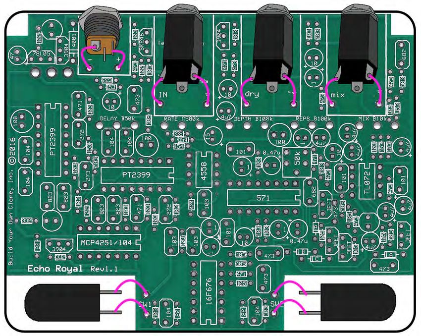
ground spots, and the TIP connection will connect to the ‘in’, ‘dry’, and
‘mix’ eyelets as shown below.
2324
Operating Overview

Blend: Controls the dry to delay ratio.
Repeats: Controls the amount of repeats in the delay.
Depth: Depth control for the modulation.
Rate: Rate control for the modulation
Delay: Sets the delay time.
Tap Multiplier: Used for Tap Tempo switch. The sweep is divided into five sections. The five
sections are listed below.
On/Off: Turns the effect on.
Tap Tempo: Allows the delay time to be set by tapping what tempo you want.
Power supply: 2.1mm negative tip
Current Draw: 80mA
Input Impedance: 1M Ohm
Output Impedance: 47k Ohm

                                                                                               25
Operating Instructions
To engage the delay effect, hit the left footswitch. When the delay effect is active,
the Blend control is a dry/delay(wet) blend. With the knob at noon, you will get a 50/50
mixture, all the way left is just the dry signal, and all the way right is the wet signal.
The Repeats knob controls how many times the delayed signal will repeat. There is the
ability to put the effect into self-oscillation.
The Depth knob controls the depth of the modulated signal, all the way left means that
there will be no modulation, all the way right means that there is intense modulation.
The Rate knob controls how fast the modulation rises and falls. All the way left is a slow
rate, all the way right is a faster rate.
The tap multiplier knob allows you to tap out 1-to-1 quarter notes, dotted eighth notes,
eighth notes, triplets, and sixteenth notes.
The Delay knob controls the rate of delay. All the way to the left is a quick, ‘slap-back’
type delay, all the way right is a longer delay time, and can reach upwards of a second of
delay time.
Tap Tempo
To enable tap tempo mode, simply start tapping on the Tap Tempo footswitch. The Tap
Tempo feature is where the Tap Multiplier potentiometer comes into play. The divisions
are:
• Quarter
• Dotted Eighth
• Eighth
• Triplets
• Sixteenths
Trails Mode
To enable trails mode, that is to say, the delayed signal will continue through it’s delay
cycle when the pedal is disengaged, delaying the signal only until the point you
disengaged the effect; press and hold the on/off switch for three seconds until you see the
Tap Tempo indicator LED blink in quick succession. To disable Trails Mode, hold the
on/off switch for another three seconds.
26Back-side PCB Photo
2728
For hi-res schematic visit http://www.byocelectronics.com/echoroyalschematic.pdf

                             Please visit
                  http://byocelectronics.com/board
                      For any technical support

                             Copyright 2019
                              BYOC, Inc.

                                                                                   29
You can also read