CAP2500 / CAP2300 Universal automatic headlight tester - USER MANUAL - Capelec
←
→
Page content transcription
If your browser does not render page correctly, please read the page content below
Rev A

      USER MANUAL

CAP2500 / CAP2300
Universal automatic headlight tester
     Passenger cars & Trucks

                                  1130, rue des Marels
                         34 000 MONTPELLIER France

                               Tél : (33) 04-67-156-156
                               Fax : (33) 04-67-224-224
                             e-mail :contact@capelec.fr

                             www.capelec.fr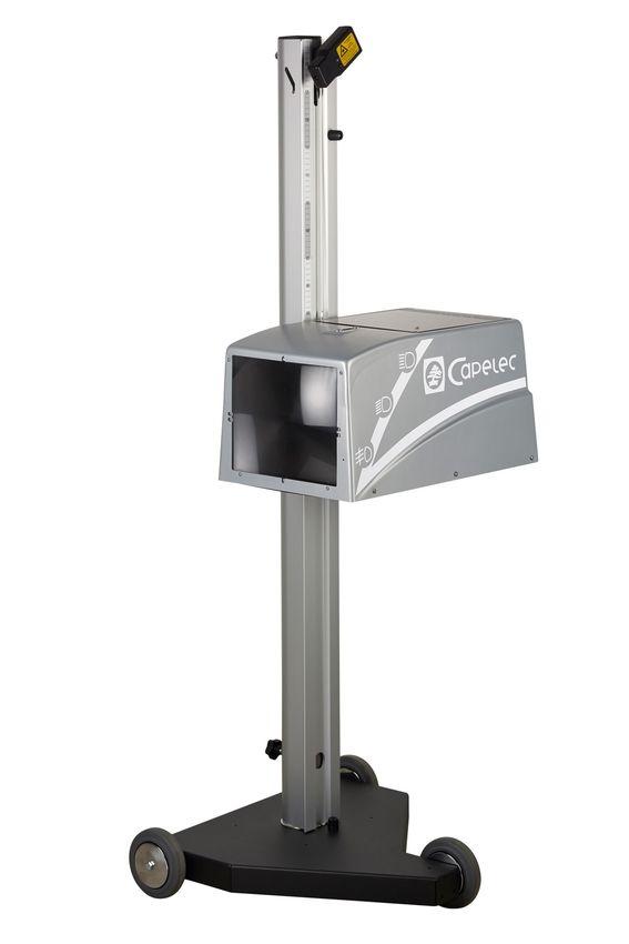
SOMMAIRE

I. Introduction ............................................................................................................................. 2
II. General description ............................................................................................................... 3
    2.1 Visualization screen ......................................................................................................... 3
    2.2 User interface ................................................................................................................... 3
    2.3 Main functions .................................................................................................................. 4
    2.4 Tester power supply......................................................................................................... 4
III Headlight tester positioning.................................................................................................. 6
    3.1 Vehicle preparation .......................................................................................................... 6
    3.2 Vehicle longitudinal axis positioning with laser ............................................................ 7
    3.3 Vehicle longitudinal axis positioning with mirror .......................................................... 8
    3.4 Optical head positioning in front of the headlamp. ....................................................... 9
IV. Vehicle inspection .............................................................................................................. 11
V. Adjustment functions .......................................................................................................... 13
    5.1 Dipped headlight adjustment function ......................................................................... 13
    5.2 High beam adjustment function .................................................................................... 14
    5.3 Fog light adjustment function ....................................................................................... 14
VI. Configuration ...................................................................................................................... 16
VII. Tester maintenance ........................................................................................................... 23
VIII. Technical characteristics ................................................................................................. 24

     30/06/16                                                         1                                               Rev A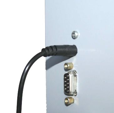
I. Introduction

We thank you for acquiring the headlight tester CAP2500 or CAP2300. This tester takes advantage of the
most advanced technologies, designed and patented by CAPELEC. The CAP2500 or CAP2300 is a
standalone device for controlling and adjusting any type of headlamp.

This manual explains how to use the CAP2500 and CAP2300 in its various versions:
   -   CAP2500 Bluetooth
   -   CAP2500 Wifi
   -   CAP2500 RS232
   -   CAP2300 RS232

Please read this manual carefully before operating the device, in order to get the full benefit of it. Keep it
in a safe place to consult it when necessary.

Remark : Information contained in this document are subject to change without prior notice. CAPELEC
will not be held responsible in any case for any damage, direct or indirect, of any kind whatever, nor for
losses or expenses, resulting from improper use.

                                              WARNING
           The lens of the system must never be exposed to sunlight.
    The concentration of sunlight can cause heating and a risk of damaging the
                             equipment and/or burns.

   30/06/16                                          2                                    Rev A
II. General description
2.1 Visualization screen
LCD screen
Visualization screen
Cut-off graduations for
visual control
2.2 User interface
The battery light indicates, when blinking, that the battery level is low.
On CAP2500, when the rechargeable batteries are in charge, the light remains on.
On CAP2300, when the non-rechargeable battery is low, please replace it.
The key « On/Off » enables to switch on the tester. To switch it off, press the key
3 seconds.
The key «Print-out» enables to print out or to send measurements.
The key «Ok» enables to validate.
The key «ESC» enables to get out of a menu.
The arrows « up » and « down » enable to move in the menus.
30/06/16 3 Rev A2.3 Main functions
5 main modes are available when the tester is on:
Menu 1: Vehicle Inspection
The menu Vehicle Inspection enable to carry out dipped headlamps cut-off control (and fog lights as an
option). Test results could be forwarded to a PC through the GIEGNET protocol. It is also possible to
print-out the results.
Menu 2: Dipped headlamps adjustment
This function enables to carry out dipped headlamps adjustment. It enables a vertical adjustment
complying with the cut-off wished by the operator. It enables a lateral adjustment at 0% only on
CAP2500. Furthermore, the tester gives the light intensity and dazzling default provided by the dipped
headlamp.
Menu 3: High beam adjustment
High beam adjustment enables to adjust these lamps at 0%, both lateral and vertical. The operator is
guided to carry out his adjustment thanks to direction arrows. Furthermore, the light intensity of the high
beam is displayed on the screen.
Menu 4: Fog light adjustment
This mode displays the cut-off measured on fog lights so that the operator can make an adjustment with
an optimal cut-off.
Menu 5: Configuration
This menu gives access to several sub-menus enabling to parameter the various functionalities of the
CAP2500 and CAP2300, such as the print-out mode choice, the date and time setting, the contrast
adjustment, etc.
2.4 Tester power supply
CAP2300
The CAP2300 is provided with R14 C-type non-rechargeable batteries.
Remark: Deactivation of backlight enables to multiply by 3 the tester autonomy.
ATTENTION: Do not try to recharge the CAP2300 batteries.
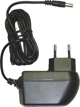
30/06/16 4 Rev ACAP2500 The CAP2500 is provided with R14 C-type rechargeable batteries. Remark: Deactivation of backlight enables to multiply by 3 the tester autonomy. When the batteries are empty, the battery light starts to blink. You must then charge them again. Connect on the rear plug of the tester the 9V charger supplied by CAPELEC. Battery charge is shown through continuous lighting of the battery light. When the light is off, the batteries are charged and then you can disconnect the charger. Remark about the charger: Disconnection device is the adapter block. Therefore, it must remain accessible. You must not use in any case another charger than the one supplied by Capelec. CAP2500 & CAP2300 Remark on the batteries: Battery replacement must be done with original parts. Battery rejection : Get rid of the batteries according to laws and regulations into effect in your own country. Do not throw used batteries in your dust bin : in most of the countries, it is forbidden by law to incinerate them, to bury them or to throw them away in rubbish dumps. Please contact local authorities for further information on measures taken in your country to collect, recycle and destroy used batteries. 30/06/16 5 Rev A
III Headlight tester positioning

3.1 Vehicle preparation
First of all, control the tyre pressure. If it is not correct, reinflation or deflation will be done to reach the
recommended pressure within – 0 bar and + 0.3 bar limits. In every case, this pressure must be balanced.

Move forward the vehicle at low speed, let it stop smoothly (without using the parking brake) on a
levelled and horizontal surface, front wheels in a straight line. By default, it is suitable that the vehicle
runs for at least 1 wheel turn (without any effort for the trains) and to stop it (without using the parking
brake) on a levelled and horizontal surface.

For vehicles with non standard suspension (e.g. : servo suspension), it is necessary to run the engine
before making any measurement, wait for the vehicle to stabilize with the engine running.

Actuate the parking brake (gradually for manual handbrakes).

When the vehicle is equipped, either in the passenger compartment or at the headlamp level, with a
manual setting system, place the device in the position recommended by the manufacturer according to
the charge state. If the system does not work, the control is made in the existing configuration.

   30/06/16                                            6                                     Rev A
3.2 Vehicle longitudinal axis positioning with laser

1- Move forward the headlight tester in front
of the centre of the vehicle so that the
headlight tester lens is within 20 and 50 cm
from each headlamp (optimal distance being
35cm).

2- Identify on the vehicle 2 fixed marks,
symetrically spread out with regard to its
central axis (examples : right and left upper
windscreen angles, non distorted engine
bonnet angles, windscreen washer jets if
their support is not distorted).

3- Make the optical head swivel so that the
laser line match with the marks identified on
the vehicle.

4- You can start with the control or
adjustment procedure. During this phase you
will move the headlight tester in front of the
headlamp to be controlled or adjusted while
keeping the angular positioning carried out
with the laser.

WARNING Laser radiation:
- Class 2M laser device
- Do not look directly into the beam nor directly observe using "magnifying" optical instruments.
- The vehicle must be empty of occupants when the laser beam is being adjusted.
- Laser adjustment must be used momentarily.

   30/06/16                                      7                               Rev A
3.3 Vehicle longitudinal axis positioning with mirror

1- Move forward the headlight tester in front
of the centre of the vehicle so that the
headlight tester lens is within 20 and 50 cm
from each headlamp (optimal distance being
35cm).

2- Identify on the vehicle 2 fixed marks,
symetrically spread out with regard to its
central axis (examples : right and left upper
windscreen angles, non distorted engine
bonnet angles, windscreen washer jets if
their support is not distorted).

3- Make the optical head swivel so that the
mirror line match with the marks identified on
the vehicle.

4- You can start with the control or
adjustment procedure. During this phase you
will move the headlight tester in front of the
headlamp to be controlled or adjusted while
keeping the angular positioning carried out
with the laser.

   30/06/16                                      8      Rev A
3.4 Optical head positioning in front of the headlamp.
Electronic positioning assistance (only available on CAP2500) allows you to be guided when
positioning the optical head in front of the headlamp. It activates itself before each cut-off
measurement for dipped headlamps. Indications displayed on the screen tell you in what
direction to move the head. When the optimal positioning is reached, « Ok » is displayed on the
screen, and the testers goes automatically to the next step.

Operating mode for CAP2500:

1- Move the headlight tester in front of the headlamp to be controlled, by visually positioning it
below the headlamp centre.

2- Follow the indications on the screen, so that to move up the optical head at the right height.

3- At last, position accurately the optical head by taking into account the indications until you get
« Ok » on the screen.

                                                         Up

                                                         Down

                                                         Forward

                                                         Backwards

   30/06/16                                      9                                 Rev A
ATTENTION: During this operation, you must be sure that the front side of the tester is not exposed to external light interference (sun, spot light), which could change the positioning. Visual positioning for CAP2300 or CAP2500: If the positioning assistance is not available on your tester, manual positioning is done by placing face-to-face the lens centre and the headlamp centre as well. 1- First, position laterally the optical head in front of the headlamp 2- Measure the headlamp centre height and position the lens centre at this level. 30/06/16 10 Rev A
IV. Vehicle inspection

In the menu 1 « Vehicle Inspection », the headlight tester will assist you along the vehicle headlamp
control. All the steps proposed by the tester will be described in the hereafter chapter.

Vehicle selection

GIEGNET Mode: vehicle number plate selection.
Connection with the PC of the station allows you to access to the number plate list of vehicles to be
controlled. First step is to select the vehicle number plate that you want to control.

                                   V1 : 120MT034

Validate your selection by pressing the key « Ok ».

Printer: vehicle number plate acquisition.
First step is to acquire the vehicle number plate to be controlled. Press keys « up » and « down » to scroll
numbers and letters to acquire and press « Ok » to go the next letter. Once the number plate is acquired,
press « Ok » until the cursor reaches the end of the line. Then, you can go ahead to the next step.

                                   Plate :000AAA34

To delete the number plate, if any mistake, press « Echap ».
If you do not want to acquire a number plate and proceed directly to the next step, press « Ok » when you
are at step 1.

Dipped headlamps
First of all, please position the headlight tester in front of the first headlamp to be controlled (See chapter
“Headlight tester positioning”).
Remark: If the « Positioning assistance » is available, the tester will tell you how to move the optical head
so that to reach the optimal position for the control.
During the measurement phase, the tester tells you which headlamp you are controlling (right or left) and
the cut-off of this one in % and light intensity in lux or kcd.

                                   R -1,2% 025kcd

            Right Headleam        Cut-off       Light intensity

High beam
As did previously, you have to:
   -   define the high beam light height to be controlled,

   30/06/16                                           11                                   Rev A
- position the tester,
- then successively control, right and left beam. The tester tells you the headlamp to be controlled,
the high beam hot spot position with arrows and light intensity in lux or kcd.
HR 125kcd
High beam Right Hot spot too much right and down Light intensity
HR >>OKV. Adjustment functions
5.1 Dipped headlight adjustment function
This function allows the operator to carry out a lateral and vertical adjustment of dipped headlights. This
operation is done in the following way:
Positioning
First of all, you must position the headlight tester in the front of the headlamp to be adjusted (See chapter
“Headlight tester positioning”).
Remark : If the « Positioning assistance » is available, the tester will tell you how to move the optical
head so that to reach the optimal position for the control.
Vertical adjustment
Adjust the headlamp to the cut-off that you want to obtain, by following the cut-off value displayed on the
screen.
Cut : -1,22%
The adjustment optimal value is generally indicated on the headlamp housing. On the contrary, the cut-off
to apply is R(%) = 2 x h(m), h being the headlamp optics centre height.
Lateral hot spot adjustment (function not available on CAP2300)
Adjust laterally the headlamp by following the indications of the arrows on the screen and try get the
indicator value to “0”.
Lat : 65
Dipped headlight hot spot must go left Indicator value
When “OK” is display on the screen, the headlamp is correctly laterally adjusted.
Lat : >>OK5.2 High beam adjustment function
Positioning
First of all, you must position the headlight tester in the front of the headlamp to be adjusted (See chapter
“Headlight tester positioning”).
Remark : If the « Positioning assistance » is available, the tester will tell you how to move the optical
head so that to reach the optimal position for the control.
Lateral and vertical hot spot adjustment
Important When you adjust dipped headlights or high beam in the same optics, the priority must be given
to the dipped headlights adjustment : an offset may exist due to the position of the filaments in the bulb.
This function allows the operator to make both lateral and vertical adjustment of high beam. First of all,
you must carry out positioning of the CAP2500 in front of the headlamp to be adjusted (See chapter IV).
Adjust laterally and then vertically the headlamp by following the indications of the arrows on the screen.
Hot spot must go left Hot spot must go up
When « Ok » is displayed on the screen, the headlamp is correctly adjusted.
>>OKVertical adjustment
The fog light adjustment function gives you the beam cut-off on the screen. Only vertical adjustment has
to be done. The fog lights must be adjusted 1% below dipped headlights.
Cut : -2,51%
For example, dipped headlights adjusted at -1.5% imply a fog light adjustment at -2.5%.
Light intensity diagnostics
125kcd
Light intensity in kcd or Lux
30/06/16 15 Rev AVI. Configuration
This menu gives access to different sub-menus enabling to parameter the tester.
5 Config…
51 Print-out
511 Data output
512 Destination
513 Printer parameter
52 Language
53 Back light
54 Date & time
55 Way of control
Right - Left
Left - Right
56 Stand by
57 Buzzer (not available on CAP2300)
58 Information
59 Maintenance
30/06/16 16 Rev A6.1 Print-out sub-menu
This menu gives access to 3 sub-menus: Data output, Destination parameter, and Printer parameter. These
sub-menus give access to different parameters according to your headlight tester type CAP2500
Bluetooth, CAP2500 WIFI, CAP2500 RS232, or CAP2300 RS232.
CAP2500 (Bluetooth version):
51 Print-out
511 Data output
GIEGNET Export
Printer
512 Destination parameter
Concentrator address
513 Printer parameter
Printer address
Com. port
Speed
Data output sub-menu
This menu allow the operator to select between GIEGNET Export and Printer. Selection between one of
these 2 modes will affect succession of the steps in the vehicle inspection procedure.
GIEGNET Export :
Enables to transfer data from the vehicle inspection to the PC of the station, or to another peripheral
complying with the GIEGnet protocol.
Printer :
Enables to print out vehicle inspection data on a Bluetooth or RS232 printer.
Destination parameter sub-menu
Not used.
30/06/16 17 Rev APrinter parameter sub-menu Printer address : This menu allows you to acquire the Bluetooth printer address on which you want to print out your results. Com. port : This menu allows you to choose on which type of printer you want to print out your results, RS232 or Bluetooth. Speed : This menu allows you to parameter the communication speed with an RS232 printer (by default 9600 Baud). 30/06/16 18 Rev A
CAP2500-WIFI :

   51 Print-out
                           511 Data output

                                                   GIEGNET Export
                                                   Printer

                           512 Destination parameter

                                                    SSID
                                                    WEP1
                                                    WEP2
                                                    Num. port
                                                    IP
                                                    Network

                                                   WIFI Module

                           513 Printer parameter
                                                    Speed

Data output sub-menu
This menu allows the operator to choose between GIEGNET Export, and Printer. Selection between one
of these modes will affect succession of the steps in the vehicle inspection procedure.

GIEGNET Export:
Enables to transfer data from the vehicle inspection to the PC of the station, or to another peripheral
complying with the GIEGnet protocol.

   30/06/16                                       19                                 Rev A
Printer:
Enables to print out vehicle inspection data on RS232 printer.
Destination parameter menu
This menu gives you access to the various network parameters in order to configure the connection at the
Wifi access point.
Printer parameter sub-menu
This menu allows you to parameter the communication speed with an RS232 printer (by default 9600
Baud).
30/06/16 20 Rev ACAP2500-RS232 and CAP2300-RS232
51 Print-out
511 Data output
GIEGNET Export
Printer
512 Destination
Speed
513 Printer parameter
Speed
Data output sub-menu
This menu allows the operator to choose between GIEGNET Export, and Printer. Selection between one
of these modes will affect succession of the steps in the vehicle inspection procedure.
GIEGNET Export :
Enables to transfer data from the vehicle inspection to the PC of the station, or to another peripheral
complying with the GIEGnet protocol.
Printer :
Enables to print out vehicle inspection data on RS232 printer.
Destination parameter destination
This menu enables to parameter the communication speed between the PC in the Giegnet Export (by
default the GIEGNET works in 2400 Baud)
Printer parameter sub-menu
This menu allows you to parameter the communication speed with an RS232 printer (by default 9600
Baud).
30/06/16 21 Rev A6.2 Language sub-menu
This menu gives you access to setting language.
6.3 Back light sub-menu
This menu allow you to activate or to deactivate LCD screen back light.
6.4 Date & time sub-menu
This menu gives you access to setting of date and time.
6.5 Way of control sub-menu
This menu allows you to choose the headlamp way of control in the vehicle inspection procedure. Right
headlamp first, then left (right – left) and inversely (left - right).
6.7 Stand-by sub-menu
This menu enables to configure when the tester is going to automatically switch off in case of inactivity
(no pressure on the keyboard keys).
6.8 Buzzer sub-menu (not available on CAP2300)
If you want it, you can deactivate the buzzer of the keyboard keys of your tester.
6.9 Information sub-menu
This menu gives you access to the following information:
- Model of the tester
- Software version
- Serial number of the tester
- Homologation
- Battery level
- Bluetooth address of the tester (if your tester is Bluetooth).
30/06/16 22 Rev AVII. Tester maintenance
Maintenance of the lens:
- Avoid to put the fingers on the lens to prevent dirtiness
- Clean it if necessary (with soapy water or with a windscreen washer product)
- If your lens is cracked or scratched too heavily you have to replace it through a service
company.
Mechanical checking:
- When operating your tester, check that the bubble of the on-board level remains in its original
position whatever the tester position.
- In case of the bubble deviates too much, please contact your service company in order a
technician checks your tester and its calibration.
30/06/16 23 Rev AVIII. Technical characteristics
Characteristics:
Weight : 25kg
LxWxH: 590 x 670 x 1550 m
Autonomy 15h on rechargeable battery in continuous operating
Quick recharge in 3h30 with automatic stop (only with CAP2500)
Operating conditions:
CAP2500 rechargeable batteries: 4 x rechargeable accumulator R14 C-Type
CAP2500 Charger power supply: 9V 2A
CAP2300 non- rechargeable batteries: 4 x cell R14 C-Type
Ambient temperature: from 5 to 40°C
Storage temperature: -15 to +55°C
Relative humidity :This symbol indicates that, in accordance with DEEE directive (2002/96/CE) and with the regulation of your country, this product should not be thrown with the household refuse. You must deposit it in a place of collecting envisaged to this end, fro example, an official site of collection of the electric components and electronics (EEE) for their recycling or a terminal point of products authorized which is accessible when you acquire of a new product of the same type as the old one. Any deviation compared to these recommendations of elimination of this type of waste can have negative effects on the environment and the public health because these products EEE generally contain substances which can be dangerous. In parallel, your whole cooperation with the good reject of this product will support a better use of the natural resources. To obtain more information on the points of collection of the equipment to be recycled, contact your town hall, the service of collection of waste, approved plan DEEE or the service of garbage collection domestic.
You can also read