CHAPTER 870 - BANK PROTECTION - EROSION CONTROL
←
→
Page content transcription
If your browser does not render page correctly, please read the page content below
Highway Design Manual 870-1
 May 20, 2022

CHAPTER 870 – BANK PROTECTION –
EROSION CONTROL
Topic 871 – General
Index 871.1 – Introduction
Highways, bikeways, pedestrian facilities and appurtenant installations are often attracted to
parallel locations along man-made channels, streams, and rivers. These locations may be
affected from the action of flowing water, and may require protective measures.
Bank protection can be a major element in the design, construction, and maintenance of
highways. This section deals with procedures, methods, devices, and materials commonly used
to mitigate the damaging effects of flowing water on transportation facilities and adjacent
properties. Potential sites for such measures should be reviewed in conjunction with other
features of the project such as long and short term protection of downstream water quality,
aesthetic compatibility with surrounding environment, and ability of the newly created ecological
system to survive with minimal maintenance. See Index 110.2 for further information on water
quality and environmental concerns related to erosion control. See Chapter 880 for shore
protection along coastal zones and lake shores that are subjected to wave attack.
Refer to Index 806.2 for definitions of drainage terms.

871.2 Design Philosophy
In each district there should be a designer or advisor, usually the District Hydraulic Engineer,
knowledgeable in the application of bank protection principles and the performance of existing
works. Information is also available from headquarters specialists in the Division of Design and
Structures Design in the Division of Engineering Services (DES). The most effective designs
result from the cooperative involvement with Design, Environmental, Landscape Architecture,
Structures, Construction, and Maintenance (for further discussion on functional responsibilities
see Topic 802). For channel and habitat characterization and assessment relative to design
and obtaining project specific permits, the designer may also require input from fluvial
geomorphologists (or engineers with geomorphology training), geologists and biologists. The
District Hydraulic Engineer will typically be able to assist with flood analysis, water surface
elevations/profiles, shear stress computations, scour analysis, and hydraulic analysis for
placement of in-stream structures. A geomorphologist can provide input regarding
characterization of channel form and dominant geomorphic processes and hydraulic geometry
relationships such as an analysis of lateral and longitudinal channel adjustment. The
geomorphologist can also make an identification of the processes responsible for forming and
maintaining key habitats and assist in making an assessment of the long-term project effects.
See Index 872.3 for project geomorphologist details.
There are a number of ways to deal with the problem of bank erosion as follows:
870-2 Highway Design Manual
May 20, 2022

• Although not always feasible or economical, the simplest way and generally the surest of
 success and permanence, is to locate the facility away from the erosive forces. Locating
 the facility to higher ground or solid support should be considered, even when it requires
 excavation of solid rock, since excavated rock may serve as a valuable material for bank
 protection.
• The most commonly used method of bank protection is with a more resistant material like
 rock slope protection (RSP). Other protection methods (e.g., training systems) are
 discussed in Index 873.4 and summarized in Table 872.1.
• A third method is to reduce the force of the attacking water. This is often done by various
 plantings such as willows. Plantings once established not only reduce stream velocity near
 the bank during heavy flows, but their roots add structure to the bank material.

• Another method is to re-direct flows away from the embankment. In the case of stream
 attack, a new channel can be created or the stream can be diverted away from the
 embankment by the use of baffles, deflectors, or spurs.

Combinations of the above four methods may be used. Even protective works destroyed in
floods have proven to be effective and cost efficient in minimizing damage to transportation
facilities.
Design of protective features should be governed by the importance of the facility and
appropriate design principles. Some of the factors which should be considered are:
• Roughness. Revetments generally are less resistant to flow than the natural channel bank.
 Channel roughness can be significantly reduced if a rocky vegetated bank is denuded of
 trees and rock outcrops. When a rough natural bank is replaced by a smooth revetment,
 the current is accelerated, increasing its power to erode, especially along the toe and
 downstream end of the revetment. Except in narrowed channels, protective elements should
 approximate natural roughness and simulate the effect of trees and boulders along natural
 banks and in overflow channels.
• Undercutting. Particular attention must be paid to protecting the toe of revetments against
 undercutting caused by the accelerated current along smoothed banks, since this is the most
 common cause of bank failure.
• Standardization. Standardization should be a guide but not a restriction in designing the
 elements and connections of protective structures.
• Expendability. The primary objective of the design is the security of the transportation
 facility, not security of the protective structure. Less costly replaceable protection may be
 more economical than expensive permanent structures.
• Dependability. An expensive structure is warranted primarily where transportation facilities
 carry high traffic volumes, where no reasonable detour is available, or where facility
 replacement is very expensive.
• Longevity. Short-lived structures or materials may be economical for temporary situations.
 Expensive revetments should not be placed on banks likely to be buried in widened
 embankments, nor on banks attacked by transient meander of mature streams.
• Rock Materials. Optimum use should be made of local materials, considering the cost of
 special handling. Specific gravity of stone is a major factor in bank protection and the
 specified minimum should not be lowered without increasing the mass of stones. See
 Index 873.3(3)(a)(2)(b) for equation to estimate rock size.
Highway Design Manual 870-3
 May 20, 2022

• Selection. Selection of class and type of protection should be guided by the intended
 function of the installation.
• Limits. Horizontal and vertical limits of protection should be carefully designed. The bottom
 limit should be secure against toe scour. The top limit should not arbitrarily be at high-water
 mark, but above it if overtopping would cause excessive damage and below it if floods move
 slowly along the upper bank. The end limits should reach and conform to durable natural
 features or be secure with respect to design parameters.

Table 872.1

Guide to Selection of Protection
 Armor Training
 Flexible Rigid Bendway
 Check
 Guide Banks Weirs and
 Mattresses Dams
 Spurs
 Vegetated RSP

 Location

 Drop Structure
 Grouted Rock

 Grouted Rock
 Conc. Lined
 Conc. Rock

 Bulk Heads
 Vegetation

 Gabions
 Rip Rap

 Conc. F

 Other

 Other
 Piling

 Piling

 Piling
 Earth
 Cribs
 Rock

 Rock

 Rock

 Rock
Cross Channel
 Young Valley X X X X X
 Mature Valley X X X X X X X X X X X X
Parallel Encroachment
 Young Valley X X X X X X
 Mature Valley X X X X X X X X X X X X X X X X
Desert-wash
 Top debris cone X X X X X
 Center debris cone X X X X X
 Bottom debris cone X X X X X
Overflow and X X X X X X X
Floodplain
Artificial Channel or X X X X X X X
Roadside Ditch X X
(Ch. 860)
Culvert
 Inlet X X X
 Outlet X X X
Bridge
 Abutment X X X
 Upstream X X X X X X
 Downstream X X X X X X X X X

871.3 Selected References
Hydraulic and drainage related publications are listed by source under Topic 807. References
specifically related to slope protection measures are listed here for convenience.
870-4 Highway Design Manual
May 20, 2022

(a) FHWA Hydraulic Engineering Circulars (HEC) – The following seven circulars were
 developed to assist the designer in using various types of slope protection and channel
 linings:
 • HEC 14, Hydraulic Design of Energy Dissipators for Culverts and Channels (2006)
 • HEC 15, Design of Roadside Channels with Flexible Linings (2005).
 • HEC 18, Evaluating Scour at Bridges (2012)
 • HEC 20, Stream Stability at Highway Structures (2012)
 • HEC 23, Bridge Scour and Stream Instability Countermeasures (2009)
 • HEC 25, Highways in the Coastal Environment (2008 with 2014 supplement)
 • HEC 26, Culvert Design for Aquatic Organism Passage (2010)
(b) FHWA Hydraulic Design Series (HDS) No. 6, River Engineering for Highway Encroachments
 (2001) – A comprehensive treatise of natural and man-made impacts and responses on the
 river environment, sediment transport, bed and bank stabilization, and countermeasures.
(c) AASHTO Highway Drainage Guidelines – General guidelines for good erosion control
 practices are covered in Volume III - Erosion and Sediment Control in Highway Construction
(d) AASHTO Drainage Manual (2014) – Refer to Chapters; 11 – Energy Dissipators; 16 –
 Erosion and Sediment Control; 17 – Bank Protection. The manual provides guidance on
 engineering practice in conformance with FHWA’s HEC and HDS publications and other
 nationally recognized engineering policy and procedural documents.
(e) U.S. Army Corps of Engineers EM 1110-2-1601 Hydraulic Design of Flood Control Channels
 Manual.
(f) California Department of Fish and Wildlife – California Salmonid Stream Habitat Restoration
 Manual.
(g) FHWA Reference Document (2019) - Two-Dimensional Hydraulic Modeling for Highways in
 the River Environment.

Topic 872 – Planning and Location Studies
872.1 Planning
The development of sustainable, cost effective and environmentally friendly protective works
requires careful planning and a good understanding of both the site location and habitat within
the stream reach and overall watershed. Planning begins with an office review followed by a
site investigation.
Google Earth can be a useful tool for determining site location, changes to stream planform
(pattern), bend radius to channel width ratio (to estimate rock size per Index 873.3(3)(a)(2)(b),
and location within the overall watershed. USGS StreamStats will facilitate simple watershed
delineation and provide basin characteristics such as area, cover and percentage of impervious
cover, average elevation, stream slope, mean annual precipitation, and peak flow from
regression equations. When more detailed watershed delineation is required, United States
Geological Survey (USGS) 7.5-minute quadrangle maps are used to trace the tributary area
and sub-basins. The USGS maps are found in graphic image form, such as TIFF and JPEG,
and are also found in the form of a Digital Elevation Model (DEM). A DEM contains x-y-z
Highway Design Manual 870-5
 May 20, 2022

topographic data point usually at 1, 10 or 30-meter grid intervals, where ”x” and “y” represent
horizontal position coordinates of a topographic point and “z” is its elevation. These data files
and the USGS 7.5-minute quadrangle image files can be imported into software programs,
including the Watershed Modeling System (WMS), Surface-water Modeling System (SMS),
AutoCAD Civil 3D, and ArcGIS.
Nearby bridges that are located along the same stream reach should be reviewed for site history
and changes in stream cross-section. All bridge files of existing bridges are located in the
Division of Maintenance, Office of Structures Maintenance.
District biologist staff should be consulted early on during the project planning phase for subject
matter expertise regarding fisheries, habitat, and wildlife and to perform an initial stream habitat
assessment.
Department biologists can be accessed through the Project Delivery Team's Environmental
Coordinator, or DEA's Biological Services Office.
For channel and habitat characterization and preliminary assessment relative to design and
acquisition of project specific permits, the initial site investigation team should include the project
engineer, the district hydraulic engineer, and a biologist. Depending on the complexity of the
project, it may be necessary to include Caltrans staff that are trained to perform a geomorphic
assessment and/or a geologist during the site investigation.
The selection of the type of protection can be determined during or following the site
investigation. For some sites the choice is obvious; at other sites several alternatives or
combinations may be applicable. See the FHWA’s HDS No. 6, River Engineering for Highway
Encroachments for a complete and thorough discussion of hydraulic and environmental design
considerations associated with hydraulic structures in moveable boundary waterways.
Some specific site conditions that may dictate selection of a type of protection different from
those shown in Table 872.1 are:
• Available right of way.
• Available materials.
• Possible damage to other properties through streamflow diversion or increased velocity.
• Environmental concerns.
• Channel capacity or conveyance.
• Conformance to new or existing structures.
• Provisions for side drainage, either surface waters or intersecting streams or rivers.
The first step is to determine the limits of the protection with respect to length, depth and the
degree of security required. For more detailed stream reconnaissance considerations, see HEC
20, Index 4.2.1 (Appendix C and D) and the FHWA’s HDS No. 6, River Engineering for Highway
Encroachments (Table 8.1).
Considerations at this stage are:
• The severity of stream attack.
• The present alignment of the stream or river and potential meander changes.
• The ratio of cost of highway replacement versus cost of protection.
870-6 Highway Design Manual
May 20, 2022

• Whether the protection should be permanent or temporary.
• Analysis of foundation and materials explorations.
• Access for construction.
• Bank slope (H:V).
• Bed and bank material gradations.
• Stream stability (lateral and vertical). Caltrans Hydromodification Requirements Guidance
 Storm Water Best Management Practices Rapid Assessment of Stream Crossings Higher
 Level Stream Stability Analysis presents 13 channel characteristics that are indicators of
 present stream stability. See Index 4.1.
• Local stream profile.
• Vegetation type and location.
• Physical habitat (temperature, shade, pools, riffles, sediment supply).
• Toe scour/bank failure mode (see Table 872.2).
• Thalweg location.
• Hardpoint location(s).
• Total length of protection needed.
The second step is the selection and layout of protective elements in relation to the highway
facility.

872.2 Class and Type of Protection
Protective devices are classified according to their function. They are further categorized as to
the type of material from which they are constructed or shape of the device. For additional
information on specific material types and shapes see Topic 873, Design Concepts.
There are two basic classes of protection, armor treatment and training works. Table 872.1
relates different location environments to these classes of protection.

872.3 Geomorphology and Site Consideration
The determination of the lengths, heights, alignment, and positioning of the protection are
affected to a large extent by the facility location environment.
An evaluation is required for any proposed highway construction or improvement that
encroaches on a floodplain. See Topic 804, Floodplain Encroachments for detailed procedures
and guidelines.
(1) Geomorphology. An understanding of stream morphology is important for identifying both
 stream instability and associated habitat problems at highway-stream locations. A study of
 the plan and profile of a stream is very useful in understanding stream morphology. Plan
 view appearances of streams are varied and result from many interacting variables. Small
 changes in a variable can change the plan view and profile of a stream, adversely affecting
 a highway crossing or encroachment. This is particularly true for alluvial streams.
 Conversely, a highway crossing or encroachment can inadvertently change multiple
 variables such as Manning’s “n-value”, channel width, and average velocity, which may
 adversely affect the stream.
Highway Design Manual 870-7
 May 20, 2022

 There is not a legal definition of geomorphologist or geomorphology under California
 regulations. The Project Geomorphologist can be one person or a team of a few
 professionals (Civil engineers, Geologists, and Engineering Geologists, and/or Geotechnical
 Engineers) involved in the project development, with experience in fluvial geomorphology
 as described above in this chapter and referenced materials. Geomorphologist design
 work falls under the umbrella of civil engineer in the California Business and Professional
 Code, Section 6731, drainage, flood control, bridges, and natural inland waterways.
 Geomorphology on Caltrans drainage projects should be under the responsible charge of a
 Civil Engineer with background in hydrology, hydraulics, sediment transport, geology and
 how these engineering forces interact with the natural waterways including the vegetation to
 create or change landforms.
 Chapter 2 in HEC 20 presents an overview of general landform and channel evolutionary
 processes to illustrate the dynamics of alluvial channel systems. It discusses lateral stability,
 factors effecting bed elevation changes, and the sediment continuity principle to provide an
 introduction to alluvial channel response to natural and human-induced change.
 River morphology and river response is discussed in detail in Chapter 5 of FHWA’s HDS
 No. 6, River Engineering for Highway Encroachments.
(2) Stream Processes. Prior to the current interest in ecology, water quality, and the
 environment, few engineers involved with highway crossings and encroachments
 considered the short-term and long-term changes that were possible or the many problems
 that humans can cause to streams. It is imperative that anyone working with rivers, either
 on localized areas or entire systems, have an understanding of the many factors involved,
 and of the potential for change within the river system. Highway construction can have
 significant general and local effects on the geomorphology and hydraulics of river systems.
 Hence, it is necessary to consider induced short-term and long-term effects of erosion and
 sedimentation on the surrounding landscape and the river. The biological response of the
 river system should also be considered and evaluated. Certain species of fish can only
 tolerate large concentrations of suspended sediment for relatively short periods of time. This
 is particularly true of the eggs and fry. It is useful for the project engineer to understand
 what is important for regulators. Some of the most common topics include:
 • Site geomorphology and steam stability
 • Stressors to historic aquatic organism habitat
 • Locations of hydraulic constrictions
 Only with such knowledge can the project engineer develop the necessary arguments to
 make the case that erosion control measures must be designed to avoid significant
 deterioration of the stream environment not only in the immediate vicinity of the highway
 encroachment or crossing, but in many instances for great distances downstream.
 Fluvial geomorphology is the science dealing with the shape of stream channels and
 includes the study of physical processes within river systems, such as bank erosion,
 sediment transport, and bed material sorting.
 This section is intended to give the engineer background, perspective, and respect of stream
 processes and their dynamics when designing and constructing bank protection for natural
 streams and to lay the groundwork for application of the concepts of open-channel flow,
 fluvial geomorphology, sediment transport, and river mechanics to the design, maintenance,
 and environmental challenges associated with highway crossings and encroachments.
 Encroachment is any occupancy of the river and floodplain for highway use. Encroachments
 usually present no issues during normal stages, but require special protection against floods.
 Classifying the regions requiring protection, the possible types of protection, the possible
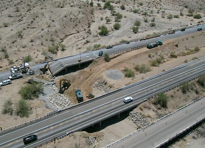
870-8 Highway Design Manual
May 20, 2022

 flow conditions, the possible channel shapes, and the various geometric conditions aids the
 engineer in selecting the design criteria for the conditions encountered.
 (a) Types of Encroachment. In the vicinity of rivers, highways generally impose a degree of
 encroachment. In some instances, particularly in mountainous regions or in river gorges
 and canyons, river crossings can be accomplished with absolutely no encroachment on
 the river. The bridge and its approaches are located far above and beyond any possible
 flood stage. More commonly, the economics of crossings require substantial
 encroachment on the river and its floodplain, the cost of a single span over the entire
 floodplain tends to be prohibitive. The encroachment can be in the form of earth fill bridge
 approach embankments on the floodplain or into the main channel itself, reducing the
 required bridge length; or in the form of piers and abutments or culverts in the main
 channel of the river. Longitudinal encroachments may exist that are not connected with
 river crossings. Floodplains often appear to provide an attractive low cost alternative for
 highway location, even when the extra cost of flood protection is included. As a
 consequence, highways, including interchanges, often encroach on a floodplain over
 long distances. In some regions, such as mountainous regions, river valleys (or canyons)
 provide the only feasible route for highways. This is true in areas where a floodplain
 does not exist. In many locations the highway encroaches on the main channel itself
 and the channel is partly filled to allow room for the roadway. See Figure 872.4. In some
 instances, this encroachment becomes severe, particularly as older highways are
 upgraded and widened.
 (b) Effects of River Development Works. These works may include water diversions to and
 from the river system, dams, cutoffs (channel straightening), levees, navigation works,
 and the mining of sand and gravel. It is essential to consider the probable long-term
 plans of all agencies and groups as they pertain to a river when dealing with the river in
 any way. For example, dams serve as traps for the sediment normally flowing through
 the river system. With sediment trapped in the reservoir, essentially clear water is
 released downstream of the dam site. This clear water has the capacity to transport
 more sediment than may be immediately available. Consequently the channel begins to
 supply this deficit with resulting degradation of the bed or banks. The degraded or
 widened main channel causes steeper gradients on tributary streams in the vicinity of
 the main channel. The result is degradation in the tributary streams. It is entirely
 possible, however, that the additional sediments supplied by the tributary streams would
 ultimately offset the degradation in the main channel. Thus, it must be recognized that
 downstream of storage structures the channel may either aggrade or degrade (most
 common) and the tributaries will be affected in either case.
 (c) Alluvial Streams. Most streams that highways cross or encroach upon are alluvial; that
 is, the streams are formed in materials that have been and can be transported by the
 stream. In alluvial stream systems, it is the rule rather than the exception that banks will
 erode; sediments will be deposited; and floodplains, islands, and side channels will
 undergo modification with time. Alluvial channels continually change position and shape
 as a consequence of hydraulic forces exerted on the bed and banks. These changes
 may be gradual or rapid and may be the result of natural causes or human activities. At
 any location in a stream, the cross-sectional shape is dependent upon the volume flow-
 rate (flow), the composition of sediment transported through a section, and the integrity
 or gradation of the bed and bank materials. As water flows through the stream channel,
 it exerts a fluid shear stress on the bed and banks. For a constant and stable cross-
 sectional shape for a given flow at a specific location, the resisting bed and bank material
 shear stress must be equal to the fluid stress at every point in the stream cross section
 perimeter. In this state, a stream is in the threshold condition where each point along
 the perimeter is at the threshold of movement or incipient motion. This condition also
 indicates a dynamic equilibrium with scour and deposition of sediment being equal. As
Highway Design Manual 870-9
 May 20, 2022

 flow, velocity, and fluid shear stress increase, the amount of scour and sediment
 deposition will change, which will also change the stream cross section for a given
 bed/bank gradation.
 Alluvial streams are commonly trapezoidal in cross section through their straight reaches
 and become asymmetric through their bends. When streams incise in response to
 possible instability, their depth increases and the stream takes on a more rectangular
 cross-sectional shape. Also, streams with very large flows may become rectangular as
 the bed width increases to convey the large flows, especially if bedrock outcroppings are
 present on the banks preventing them from flattening.
 (d) Non-Alluvial Streams. Some streams are not alluvial. The bed and bank material is very
 coarse, and except at extreme flood events, do not erode. These streams are classified
 as sediment supply deficient, i.e., the transport capacity of the streamflow is greater than
 the availability of bed material for transport. The bed and bank material of these streams
 may consist of cobbles, boulders, or bedrock. In general these streams are stable, but
 should be carefully analyzed for stability at large flows. A study of the plan and profile of
 a stream is useful in understanding stream morphology. Plan view appearances of
 streams are varied and result from many interacting variables. Small changes in a
 variable can change the plan view and profile of a stream, adversely affecting a highway
 crossing or encroachment. This is particularly true for alluvial streams. Conversely, a
 highway crossing or encroachment can inadvertently change a variable, adversely
 affecting the stream.
 (e) Dynamics of Natural Streams. Long-term climatic and tectonic fluctuations have caused
 major changes of river morphology, but rivers can display a remarkable propensity for
 change of position and morphology in time periods of a century. For shorter time periods
 river channels will shift through erosion and deposition at bends and may form chutes,
 islands or oxbow lakes. Lateral migration, erosion and deposition rates are not linear;
 i.e., a river may maintain a stable position for several years and then experience rapid
 movement. At low flow the bed of a sand bed stream can be dunes, but at large flows
 the bed may become plane or have antidune flow. With dunes, resistance to flow is large
 and bed material transport is low. Whereas, with plane bed or antidune flow the
 resistance to flow is small and the bed material transport is large. Much, therefore,
 depends on flood events, bank stability, permanence of vegetation on banks and the
 floodplain and watershed land use.
 In summary, archaeological, botanical, geological, and geomorphic evidence supports
 the conclusion that most rivers are subject to constant change as a normal part of their
 morphologic evolution. Therefore, stable or static channels are the exception in nature.
 If an engineer modifies a river channel locally, if not designed properly, this local change
 may cause unintended modification of channel characteristics both up and down the
 stream. The response of a river to human-induced changes often occurs in spite of
 attempts by engineers to keep the anticipated response under control. The points
 that should be stressed are that a river through time is dynamic and that human-induced
 change frequently sets in motion a response that can be propagated upstream or
 downstream for long distances.
 In spite of their complexity, all rivers are governed by the same basic forces. The design
 engineer must understand, and work with these natural forces:
 • Geological factors, including soil and seismic conditions.
 • Hydrologic factors, including possible changes in flows, runoff, and the hydrologic
 effects of changes in land use.
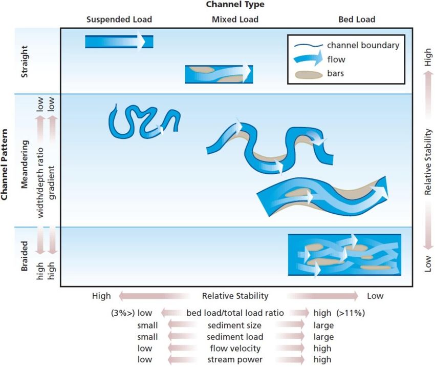
870-10 Highway Design Manual
May 20, 2022

 • Geometric characteristics of the stream, including the probable geometric alterations
 that will be activated by the changes a project and future projects will impose on the
 channel.
 • Hydraulic characteristics such as depths, slopes, and velocity of streams and what
 changes may be expected in these characteristics in space and time.
 • Sea level rise may also cause river instability, particularly when the 75-year design
 life of a bridge is considered.
 (f) Basic Stream Pattern. The three basic stream patterns are straight, braided, and
 meandering as seen in aerial or plan view. Pattern is one way of classifying a stream
 and generalizing its behavior, another is sediment load. See Figure 872.1.
 Commonly, stream patterns are identified by sinuosity, which is defined as channel
 length divided by valley (floodplain) length. For straight and braided streams, sinuosity
 varies between 1.0 and 1.5, while meandering streams have sinuosity greater than 1.5.
 These different patterns and their associated gradients contribute to changes and
 adjustments in streams, and specifically influence flow resistance that effects sediment
 transport and formation of cross-sectional shape. Engineers using any stream
 classifications should be aware that they are artificial constructs, and no strict science
 laws or principles of classification (such as used in biology) are possible. Although we
 may assign channel reaches to discrete categories based on arbitrary thresholds of
 slope, sinuosity, bed material size, sediment load, width-depth ratio, etc., these quantities
 vary continuously, and channels tend to behave in rather individualistic fashion. Different
 types of streams occur within a given subregion. Caltrans Hydromodification
 Requirements Guidance presents the various stream forms within each of the
 physiographic subregions of California, and is available from the Headquarters Office of
 Hydraulics and Stormwater Design.
 (g) Straight Streams. Straight river channels can be of two types. The first forms on a low-
 gradient valley slope, has a low width-depth ratio channel, and is relatively stable. The
 first type of straight channel may contain alternate islands or bars that result in a sinuous
 thalweg (flow path connecting deepest points in successive cross sections) within the
 straight channel. It may seem that the first type of straight stream is very stable because
 of low slope and energy, but alternating sediment deposits can cause lateral instability.
 In general, it is more natural for a stream to meander than to have a straight stream
 pattern, therefore it is difficult to find low-gradient straight streams in the field, especially
 long reaches.
 The second type is a steep gradient, high width-depth ratio, high energy river that has
 many islands or bars, and at low flow is braided. It is relatively active.
 In general, the designer should not attempt to develop straight channels fully protected
 with riprap. In a straight channel the alternate islands or bars and the thalweg are
 continually changing; thus, the current is not uniformly distributed through the cross-
 section but is deflected toward one bank and then the other.
Highway Design Manual 870-11
 May 20, 2022

Figure 872.1

Stream Classification
870-12 Highway Design Manual
May 20, 2022

 (h) Braided Streams. Similar to straight streams, streams with braided pattern have low
 sinuosity, but have the highest gradient of any of the stream patterns. Braided streams
 have many sub-channels within the main stream channel that interweave and crisscross.
 The sub-channels are separated by islands or bars which are visible during low flows
 and normally submerged under high flows. Because braided streams have steep slopes,
 they possess the higher energy necessary to erode and transport sediment that
 comprises the bars and islands. Even though braided streams have high energy, these
 streams will deposit their coarser and larger material that cannot be physically
 transported by the stream’s average velocity and shear stress. In other words, the
 process of braiding occurs during flood events as a stream adjusts in response to the
 larger sediment and debris loads that cannot be sustained while trying to find dynamic
 equilibrium. This deposition of larger material creates the bars and islands. See Figure
 872.2. As flow and velocity fluctuate during a flood event, it is common to see movement
 and re-creation of bars, islands, and sub-channels.

Figure 872.2

Diagram of a Braided River Channel

 (i) Meandering Streams. Meandering is the most common stream pattern, having a series
 of alternating curves or bends, and is associated with flatter valleys. Meandering stream
 types have the highest sinuosity because of their longer stream length, due to several
 alternating curves, with respect to valley length, see Figure 872.6. One way that streams
 seek dynamic equilibrium is to dissipate energy through erosion of their banks, creating
 meandering patterns. When meanders are created, overall stream length is increased,
 and energy is released through the work necessary to scour its banks, which brings a
 stream closer to dynamic equilibrium. Streambank revetments are often constructed
 through these meanders to prevent excessive erosion that may cause instability of
 nearby or adjacent transportation facilities.
 Once curves have been created in a stream’s alignment, velocity increases as the flow
 of water moves through the outside bank of a bend caused by secondary circulation
 currents. Given the geometry of a curve, velocity is resolved into three components
 described in the longitudinal, width-wise, and vertical directions, contrary to straight
 reaches of stream.
 As flow moves through a curve, the circulation currents and their turbulence are
 influenced by radius of curvature, stream bottom width, flow depth, curve deflection
 angle, and Reynolds Number. As often occurs, turbulence is magnified by counter-
 circulating currents from an upstream bend merging with circulating currents of an
 immediate downstream bend. The increased turbulence usually increases the amount
 of scour at the outside bend, and the transported material is deposited on the inside bend
 at the downstream reversing curve creating a point island or bar.
 Another characteristic of flow through a curve is that the top of the water surface will
 superelevate along the outside bank of a curve as it is pulled by centrifugal forces while
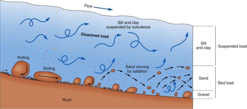
Highway Design Manual 870-13
 May 20, 2022

 the bottom water surface at the bed is being pulled toward the inside of a bend. These
 two actions will cause skewing of the circulating current contributing to increased erosion
 around a bend.
 (j) Sediment Transport. For engineering purposes, the two sources of sediment transported
 by a stream are: (1) bed material that makes up the stream bed; and (2) fine material
 that comes from the banks and the watershed (washload). Geologically both materials
 come from the watershed, but for the engineer, the distinction is important because
 the bed material is transported at the capacity of the stream and is functionally related to
 measurable hydraulic variables. The washload is not transported at the capacity of the
 stream. Instead, the washload depends on availability and is not functionally related to
 measurable hydraulic variables.
 The division size between washload and bed sediment load is sediment size finer than
 the smallest 10 percent of the bed material. It is important to note that in a fast flowing
 mountain stream with a bed of cobbles the washload may consist of coarse sand sizes.
 For these conditions, the transport of sand sizes is supply limited. In contrast, if the bed
 of a channel is silt, the rate of bed load transport of the silt sizes is less a question of
 supply than of capacity.
 When a river reaches equilibrium, its transport capacities for water and sediment are in
 balance with the rates supplied. In fact, most rivers are subject to some kind of control
 or disturbance, natural or human-induced that gives rise to non-equilibrium conditions.
 HDS No. 6, Index 4.3.2, states total sediment load can be expressed by three equations:
 1. By type of movement
 LT = Lb + Ls
 2. By method of measurement
 LT = Lm + Lu
 3. By source of sediment
 LT = Lw + Lbm
 Where:
 LT = Total load;
 Lb = Bed load which is defined as the transport of sediment particles that are close
 to or maintain contact with the bed;
 Ls = Suspended load defined as the suspended sediment passing through a stream
 cross-section above the bed layer;
 Lm = Measured sediment;
 Lu = Unmeasured sediment that is the sum of bed load and a fraction of suspended
 load below the lowest sampling elevation;
 Lw = Wash load which is the fine particles not found in the bed material (Ds < D10),
 and originates from available bank and upstream supply;
 Lbm= Capacity limited bed material load.
 Streams are unique from other hydraulic conveyance facilities, such as engineered
 channels and pipes, in that its boundaries are mobile, and they move sediment within
 their water column or along the bed by skipping and rolling, which is a complicated
 interrelationship. The suspended sediment load is carried through the flow by turbulence
 and is typically fine sand, silt, and clay. Bedload is coarser possibly as large as boulders,
870-14 Highway Design Manual May 20, 2022 and moves along the bed by fluid stress action, see Figure 872.3. Sediment supply and its movement are the life of a stream that can become unstable when this process is interrupted if supply becomes limited or if a stream is unable to transport its excess downstream. Instability can be seen through channel incision, where the stream bed degrades and banks over steepen, excessive meandering, or large alignment shifts as a stream attempts to control energy as it searches for dynamic equilibrium. The ability of a stream to control and manage its sediment is not the only influence on stream stability, but one of the more important factors. Within a stream bed, immersed sediment particles resting on the stream bed over other particles exert their effective weight in the form of a vertical force, which can be divided into normal and tangential components based on the stream bed slope. Simply stated, in order for sediment particles to become mobile, a force greater than their normal weight must be applied to them. This force that causes mobility is a drag force or fluid stress acting on the particle as water flows over them. The fluid stress can be expressed as an average boundary shear stress acting on a stream bed considering steady, uniform flow: σ0 = γw DSf Where: σ0 = Shear stress = Force per unit area in flow direction; w = Specific weight of water; D = Flow-depth; Sf = Friction slope. Particle movement can be further expressed at a specific point in a stream bed as incipient motion, which is the initial movement of a particle. The calculation of a critical shear stress or critical velocity can be performed at the threshold movement condition that assumes active hydraulic forces are equal to particle resistant forces. At the point of critical shear stress or critical velocity, a particle is just about to move. This means that values of shear stress or velocity greater than critical shear stress or critical velocity cause particles to be in motion, while particles will be at rest with values of shear stress and velocity lower than critical shear stress and velocity. An incipient motion calculation can provide an indication of erosion potential and stream stability. Fischenich (2001) provides a variation of the widely accepted and industry standard Shields equation for approximated critical shear stress considering different materials: Clays: = 0.5 (γs − γ ) tan F Silts & Sands: σcr = 0.25d0 − 0.6d(γs − γw ) tan F Gravels & Cobbles: σcr = 0.06d(γs − γw ) tan F Where: 1⁄ d0 = d[(Sg − 1)gν−2 ] 3 ; σcr =Critical shear stress; F = Soil grain angle of repose;
Highway Design Manual 870-15
 May 20, 2022

 d = Soil diameter;
 γs = Specific weight of sediment;
 γ =Specific weight of water;
 Sg = Sediment specific gravity;
 g = Gravity;
 ν = Water/sediment mixture kinematic viscosity.
 The Shields equation and the beginning of motion is described in more detail in Index
 3.5 of HDS No. 6.

Figure 872.3

Bed Load and Suspended Load

 Modeling of a stream reach, although complex, can be performed in order to predict
 sediment transport potential on a larger scale, transport rates, volume, and capacity
 modeling. Several empirical sediment transport functions used in modeling have been
 developed and named after their creators, such as Einstein, Acker and White, Laursen-
 Copeland, Meyer-Peter Muller, and Yang. These functions are complex and notoriously
 data intensive. Three classic sediment transport formulae are discussed in detail in Index
 4.5 of HDS No. 6 to illustrate sediment transport processes. While not often, resource
 agencies and flood control districts may request this type of analysis during the permit
 review process. If sediment modeling is necessary, HEC-RAS v4.1 (or higher), the Army
 Corps of Engineers’ river and stream modeling software, contains sediment transport
 modeling capabilities using these transport functions and others.
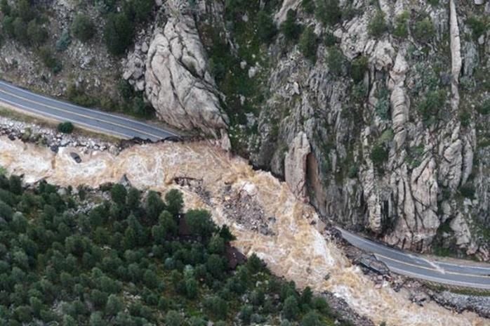
870-16 Highway Design Manual
May 20, 2022

Figure 872.4

Longitudinal Encroachments

Highway 49, North Fork Yuba River (Near Downieville) and Highway 190, Furnace Creek,
(Death Valley)

 (k) Stream Channel Form. Major factors affecting alluvial stream channel forms are:
 • stream discharge, viscosity, temperature;
 • sediment discharge;
 • longitudinal slope;
 • bank and bed resistance to flow;
 • vegetation;
 • geology, including types of sediments and;
 • human activity.
 At any location in a stream, the cross-sectional shape is dependent upon the volume
 flow-rate (flow), the composition of sediment transported through a section, and the
 integrity or gradation of the bed and bank materials. As water flows through the stream
 channel, it exerts a fluid shear stress on the bed and banks. For a constant and stable
Highway Design Manual 870-17
 May 20, 2022

 cross-sectional shape for a given flow at a specific location, the resisting bed and bank
 material shear stress must be equal to the fluid stress at every point in the stream cross
 section perimeter. In this state, a stream is in the threshold condition where each point
 along the perimeter is at the threshold of movement or incipient motion. This condition
 also indicates a dynamic equilibrium with scour and deposition of sediment being equal.
 As flow, velocity, and fluid shear stress increase, the amount of scour and sediment
 deposition will change, which will also change the stream cross section for a given
 bed/bank gradation.
 The form and appearance of a stream can also be influenced by features within the
 stream profile, such as riffles and pools because of their effects on the acting fluid shear
 stress and velocity. Riffles are longitudinal sections of streams with higher velocity,
 where lower flow-depth usually caused by obstructions, such as gravels, cobbles, and
 boulders created by island or bar development. On the contrary, pools have higher flow-
 depth and lower velocity, and are typically comprised of finer silts and sands compared
 to a riffle. These bed materials associated with pools and riffles have an effect on
 resisting bed shear stress that will influence stream shape and stability. The alternating
 pool and riffle sequence is common for nearly all perennial streams that have gravel to
 boulder size bed formations. Different types of streams occur within a given subregion.
 Caltrans Hydromodification Requirements Guidance presents the various stream forms
 within each of the physiographic subregions of California, and is available from the
 Headquarters Office of Hydraulics and Stormwater Design.
 (l) Floodplain Form. From a geomorphic perspective, floodplains are flatter lands adjacent
 to a river main channel that are dry until larger flows force water out of the stream channel
 into these overbank lands during significant flood events. Floodplains typically include
 the following features: the main stream channel itself, point islands or bars, oxbows and
 lakes, natural raised berms (levees) above floodplain surface, terraces, sloughs and
 depressions, overbank fine and coarse sediment deposition, scattered debris, and
 vegetation.
 When water exceeds the capacity of the main channel, the conveyance of flow through
 the floodplain overbanks will differ from the main channel due to uniqueness of form
 (shape), gradient, alignment, and likely the flow resistance (roughness) of the floodplain
 versus the stream channel. Therefore, water will move and deposit varying sediment
 types differently, also at different frequency, creating a separate floodplain form. Once
 sediment is moved to the floodplain, coarser sediment is generally deposited along the
 streambanks forming levees, while finer sediment is dropped between the valley walls
 and the levees on the floodplain floor. Sediment is stored and becomes dormant until
 larger flows return to the floodplain that may convey the sediment down-valley.
 Similar to the stream channel, floodplain form is directly linked to the sediment transport
 process, as well as floodplain stability affected by sediment supply and its movement.
 Fluid shear stress and velocity control the sediment/debris degradation and deposition
 properties within the floodplain that impact its form, landscape, and appearance.
 Because the floodplain can be dormant for considerable time depending on watershed
 hydrology, its form can remain relatively constant and preserved for extended periods,
 as well as be less dynamic than the stream channel.
 (m)Streambank Erosion. Simply defined, streambank erosion occurs when the soil resisting
 strength is less than the driving forces acting on the bank. It can occur through bank-toe
 scour below the water line and bank mass failure from above. This erosion occurs first
 as a geotechnical failure followed by the hydraulic action that removes the failed soil and
 sediment by fluid shear stress. The hydraulic action further causes lateral scour of the
 bank and is the principal contributor to bank-toe failure. This is a natural process for both
 stable and unstable streams, but is exaggerated in the latter case. The degree of erosion
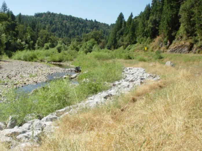
870-18 Highway Design Manual
May 20, 2022

 can be influenced by impervious development in the watershed, agricultural use, and
 changes in climate. With or without these influences and whether a stream is stable or
 unstable, streambank erosion will take place at some level. Therefore, scour must be
 reduced at critical locations to protect highway structures and preserve public safety,
 although restraint needs to be exercised during the project development process so that
 a stream does not greatly change its morphology in response to the protection measures.
 The driving and resisting forces for streambank erosion, mentioned above, are controlled
 by a series of factors. The factors that influence the calculation of the driving (active)
 forces within geotechnical failure are soil saturated unit weight, pore pressure, bank
 height, and angle of repose, as well as object surcharges within and above the bank such
 as vegetation. The effects of driving forces are commonly seen through soil saturation
 as a result of intense precipitation with subsequent increase in pore pressure and bank
 soil saturated unit weight that can cause mass bank failure. The forces that will resist
 and give soil its strength from geotechnical type failure are dependent upon effective soil
 cohesion, normal stress, pore pressure, and soil effective angle of friction.
 During streambank erosion, the bank soil can fail by different modes. Generally
 speaking, steep slopes present slab-type or toppling failures where large slabs (blocks
 of soil) of the bank break away from the top and fall into the stream, while mild slopes
 show a rotational failure that begins at the bank toe causing soil to slide from above into
 the stream. Once the eroded soil reaches flowing water, it is usually transported
 downstream depending upon its size and composition.
 As for bank-toe scour, its main influences are derived from bank soil composition and
 gradation, volume of sediment in transport, stream flow and stream gradient. These
 factors and the principles of scour and sediment movement from hydraulic forces are a
 reoccurring theme in fluvial geomorphology. The following paragraphs summarize the
 characteristics of unstable and stable banks;
 (1) Unstable banks with moderate to high erosion rate occur when the slope angle of
 unstable banks typically exceed 30 percent, where a cover of woody vegetation is
 rarely present. At a bend, the point island or bar opposite of an unstable cut bank is
 likely to be bare at normal stage, but it may be covered with annual vegetation and
 low woody vegetation, particularly willows. Where very rapid erosion is occurring, the
 bankline may have irregular indentations. Fissures, which represent the boundaries
 of actual or potential slump blocks along the bankline indicate the potential for rapid
 bank erosion.
 (2) Unstable banks with slow to moderate erosion rate occur when a bank is partly
 graded (smooth slope) and the degree of instability is difficult to assess where
 reliance is placed mainly on vegetation. The grading of a bank typically begins with
 the accumulation of slumped material at the base such that a slope is formed and
 progresses by smoothing of the slope and the establishment of vegetation.
 (3) Stable banks with very slow erosion rate occur where banks tend to be graded to a
 smooth slope and the slope angle is usually less than about 30 percent. In most
 regions, the upper parts of stable banks are vegetated, but the lower part may be
 bare at normal stage, depending on bank height and flow regime of the stream.
 Where banks are low, dense vegetation may extend to the water's edge at normal
 stage. Mature trees on graded bank slopes are particularly convincing evidence for
 bank stability. Where banks are high, occasional slumps may occur on even the most
 stable graded banks. Shallow mountain streams that transport coarse bed sediment
 tend to have stable banks.
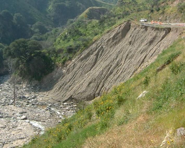
Highway Design Manual 870-19
 May 20, 2022

 For a more detailed discussion of bank stability and the mechanics of bank failure see
 HEC 20.
 (n) Young Valley. Typically young valleys are narrow V-shaped valleys with streams on
 steep gradients. Relief elevation greater than 1,000 ft is regarded as mountainous, while
 relief in the elevation range of 100 to 1,000 ft is regarded as hilly. Streams in
 mountainous regions are likely to have steep slopes, coarse bed materials (gravel or
 cobble-boulder), narrow floodplains, and have nonalluvial characteristics (i.e., supply-
 limited sediment transport rates). At flood stage, the stream flow covers all or most of
 the valley floor. The usual situation for such locations is a structure crossing a well-
 defined channel in which the design discharge will flow at a moderate to high velocity.
 (1) Cross-Channel Location. A cross channel location is a highway crossing a stream
 on normal or skewed alignment. The erosive forces of parallel flow associated with
 a normal crossing are generally less of a threat than the impinging and eddy flows
 associated with a skewed crossing. The effect of constriction by projection of the
 roadway embankment into the channel should be assessed.
 Characteristics to be considered include:
 • Stream velocity.
 • Scouring action of stream.
 • Bank stability.
 • Channel constrictions (artificial or natural).
 • Nature of flow (tangential or curvilinear).
 • Areas of impingement at various stages.
 • Security of leading and trailing edges.
 Common protection failures occur from:
 • Undermining of the toe (inadequate depth/size of foundation), see Figure 872.5
 and Table 872.2.
 • Local erosion due to eddy currents.
 • Inadequate upstream and downstream terminals or transitions to erosion-resistant
 banks or outcrops.
 • Structural inadequacy at points of impingement overtopping.
 • Inadequate rock size, see Table 872.2.
 • Lack of proper gradation/ layering/ RSP fabric, leading to loss of embankment,
 see Table 872.2.
 Any of the more substantial armor treatments can function properly in such exposures
 providing precautions are taken to alleviate the probable causes of failure. If the
 foundation is questionable for concreted-rock or other rigid types it would not be
 necessary to reject them from consideration but only to provide a more acceptable
 treatment of the foundation, such as heavy rock or sheet piling.
 Whether the highway crosses a stream channel on a bridge or over a culvert,
 economic considerations often lead to constriction of the waterway. The most
 common constriction is in width, to shorten the structure. Next in frequency is
 obstruction by piers and bents of bridges or partitions of multiple culverts.
870-20 Highway Design Manual
July 1, 2020

Table 872.2

Failure Modes and Effects Analysis for Riprap Revetment
 Effects on Effects on
 Detection Compensating
Failure Modes Other Whole
 Methods Provisions
 Components System
 • Reduce bank
 slope
 • Mound of • Use more
Translational rock at bank angular or
 Disruption of Catastrophic toe
slope or slump smaller rock
 armor layer failure
(slope failure) • Unprotected • Use granular
 upper bank filter rather
 than geotextile
 fabric
 • Rock moved
 downstream • Increase rock
Particle erosion Loss of armor from original size
 Progressive
(rock layer, erosion location
 failure • Modify rock
undersized) of filter
 • Exposure of gradation
 filter
 • Scalloping of
 upper bank
Piping or • Use
erosion Displacement Progressive • Bank cutting appropriate
beneath armor of armor layer failure granular or
 • Void beneath
(improper filter) geotextile filter
 and between
 rocks
 • Slumping of • Increase size,
Loss of toe or Displacement rock
 Catastrophic thickness,
key (under or disruption
 failure • Unprotected depth or extent
designed) or armor layer
 upper bank of toe or key
Highway Design Manual 870-21
 May 20, 2022

Figure 872.5

Slope Failure Due to Loss of Toe

 The risk of constricting the width of the waterway is closely related to the relative
 conveyance of the natural waterway obstructed, the channel scour, and to the
 channel migration. Constricting the width of flow at structures has the following
 effects:
 • Increase in the upstream water surface elevation (backwater profile).
 • Increase in flow velocity through the structure opening (waterway).
 • Causes eddy currents around the upstream and downstream ends of the
 structure.
 Unless protection is provided the eddy currents can erode the approach roadway
 embankment and the accelerated flow can cause scour at bridge abutments. The
 effects of erosion can be reduced by providing transitions from natural to constricted
 and back to natural sections, either by relatively short wingwalls or by relatively long
 training embankments or structures.
 Channel changes, if properly designed, can improve conditions of a crossing by
 reducing skew and curvature and enlarging the main channel. Unfortunately, there
 are "side effects" which actually increase erosion potential. Velocity is almost always
 increased by the channel change, both by a reduction of channel roughness and
 increase of slope due to channel shortening. In addition, channel changes affecting
 stream gradient may have upstream and/or downstream effects as the stream adjusts
 in relation to its sediment load.
 At crossing locations, lateral erosion can be controlled by positive protection, such as
 armor on the banks, rock spurs to deflect currents away from the banks, retards to
 reduce riparian velocity, or vertical walls or bulkheads. The life cycle cost of such
 devices should be considered in the economic studies to choose a bridge length
 which minimizes total cost.
 Accurate estimates of anticipated scour depths are a prerequisite for safe, cost
 effective designs. Design criteria require that bridge foundations be placed below
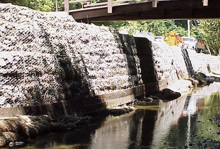
870-22 Highway Design Manual
May 20, 2022

 anticipated scour depths. For this reason, the design of protection to control scour at
 such locations is seldom necessary for new construction. However, if scour may
 undercut the toes of dikes or embankments positive methods including self-adjusting
 armor at the toe, jetties or retards to divert scouring currents away from the toe, or
 sill-shaped baffles interrupting transport of bedloads should be considered.
 There is the potential for instability from saturated or inundated embankments at
 crossings with embankments projecting into the channel. Failures are usually
 reported as "washouts", but several distinct processes should be noted:
 • Saturation of an embankment reduces its angle of repose. Granular fills with high
 permeability may "dissolve" steadily or slough progressively. Cohesive fills are
 less permeable, but failures have occurred during falling stages.
 • As eddies carve scallops in the embankment, saturation can be accelerated and
 complete failure may be rapid. Partial or total losses can occur due to an upstream
 eddy, a downstream eddy, or both eddies eroding toward a central conjunction.
 Training devices or armor can be employed to prevent damage.
 • If the fill is pervious and the pavement overtopped, the buoyant pressure under
 the slab will exceed the weight of slab and shallow overflow by the pressure head
 of the hydraulic drop at the shoulder line. A flat slab of thickness, t, will float when
 the upstream stage is 4t higher than the top of the slab. Thereafter the saturated
 fill usually fails rapidly by a combination of erosion and sloughing. This problem
 can occur or be increased when curbs, dikes, or emergency sandbags maintain a
 differential stage at the embankment shoulder. It is increased by an impervious
 or less pervious mass within the fill. Control of flotation, insofar as bank protection
 is concerned, should be obtained by using impervious armor on the upstream face
 of the embankment and a pervious armor on the downstream face.
 Culvert problem locations generally occur in and along the downstream transition.
 Sharp divergence of the high velocity flow develops outward components of
 velocity which attack the banks directly by impingement and indirectly by eddies
 entrained in quieter water. Downward components and the high velocity near the
 bed cause the scour at the end of the apron.
 Standard plans of warped wingwalls have been developed for a smooth transition
 from the culvert to a trapezoidal channel section. A rough revetment extension to
 the concrete wingwalls is often necessary to reduce high velocity to approximate
 natural flow. Energy dissipaters may be used to shorten the deceleration process
 when such a transition would be too long to be economical. Bank protection at
 the end of wingwalls is more cost effective in most cases.
 (2) Parallel Location. With parallel locations the risk of erosion damage along young
 streams increases where valleys narrow and gradients steepen. The risk of erosion
 damage is greatest along the outer bend of natural meanders or where highway
 embankment encroaches on the main channel.
 The encroaching parallel location is very common, especially for highways following
 mountain streams in narrow young valleys or canyons. Much of the roadway is
 supported on top of the bank or a berm and the outer embankment encroaches on
 the channel in a zone of low to moderate velocity. Channel banks are generally stable
 and protection, except at points of impingement, is seldom necessary.
 The constricting parallel location is an extreme case of encroaching location, causing
 such impairment of channel that acceleration of the stream through the constriction
 increases its attack on the highway embankment requiring extra protection, or
You can also read