CLASSIFICATION REPORT - Sotech Optima
←
→
Page content transcription
If your browser does not render page correctly, please read the page content below
SYSTEM BRIEF DETAIL
                                                    Report detailing the testing of a
                                                   Sotech Optima TFC+ aluminium
                                                        rainscreen system tested in
                                                   accordance with the requirement
                                                    as described in British Standard
                                                                               84144

CLASSIFICATION
REPORT                                                                  10536

BR 135 Classification Report

Prepared by:                                                     Prepared for:
The Fire Protection Association                                   Sotech Ltd
London Road                                                            Unit 2
Moreton-in-Marsh                                     Whitehouse Business Park
Gloucestershire                                                      Peterlee
GL56 9LH                                                      County Durham
                                                                    SR8 2RU

Report Date(s):                   15/06/2020

Report Reference:                 102034.002.135       Version number:      4.0
Report Number/Version
Commercial in Confidence
FPA102034.002.135/4.0
This report, and the underlying work on which it is based, has been prepared and is
submitted in accordance with the contract with the client and is intended solely for use by
the client.
FPA warrants that the report has been prepared with all reasonable skill and care. FPA
will accept liability for deficiencies in any report caused by its breach of contract or
negligence. Negligence shall be as defined as in Section 1(1) of the Unfair Contract Terms
Act 1977. Except in the case of death or personal injury arising from the negligence of
FPA, liability of FPA for breach of contract or negligence or otherwise in relation to the
preparation of the report shall in no case exceed the fee paid by the Client for the report.
FPA shall in no circumstances be liable for any other loss, charges, damages, indirect or
consequential loss (including loss of profit) or expenses of any kind. The Client
acknowledges that all possible circumstances in which the report may have some
relevance cannot be foreseen at the time the report is prepared. The Client also
acknowledges that FPA would not be able to provide the Report for the agreed fee if FPA
were obliged to accept all far-reaching responsibilities.
The scope of any report produced by FPA shall be limited to matters specifically identified
in the Proposal or indicated in the report. Except where FPA has otherwise agreed in
writing, FPA shall not be liable for any reliance placed on a report by any person other
than the Client or for any reliance placed on a report which is not specified in or envisaged
by the Proposal. FPA shall not be liable for any loss caused by a report where such loss
arises as a result of the provision to FPA of false, misleading or incomplete information by
the Client or as a result of the act or omissions of any other person.
Any report shall only be valid and may only be relied upon for the period stated in the
report. FPA accepts no responsibility for the accuracy of information contained in the
report after the stated period of validity. Where so indicated by FPA any report is to be
regarded as expressing the opinion only of FPA and is not to be relied upon as being
factually correct.
10536
Page - 2 - of 14Report Number/Version
Commercial in Confidence
FPA102034.002.135/4.0
Review
Approval Name Date
Author Tim Cansiz 20/02/2020
Reviewed and authorised by John Harbottle 14/05/2020
Reviewer/authoriser’s signature
Distribution
Name Company
Lee Gravett Sotech Ltd
Graham Todd Sotech Ltd
Document version history
Version Date Superseded documents/description/details
1.0 15/05/2020 Initial version
2.0 28/05/2020 Updated with revised distribution list and extra
installation photographs
3.0 15/06/2020 Updated to include corrected material specification
4.0 02/07/2020 Updated following revisions to the accompanying
BS 8414 Test Report
Disclaimer
This report has been produced by the Fire Protection Association for Sotech Ltd
• This report may only be distributed in its entirety, without amendment.
• Results presented relate only to the specimens tested.
• FPA takes no responsibility for the design, materials, workmanship or performance of the
product tested.
• The report does not constitute an approval, certification or endorsement of the products tested.
• Any references made to this work must be accompanied by provision of the full, unabridged,
report.
• The report does not imply that FPA believe the BS8414 test regime alone is appropriate for the
guarantee of end-use system performance.
Page - 3 - of 14Report Number/Version
Commercial in Confidence
FPA102034.002.135/4.0
Contents
1 Introduction ..................................................................................................................................- 5 -
2 Details of the test carried out .......................................................................................................- 6 -
3 Analysis of fire performance and classification ............................................................................- 7 -
3.1 Test procedure ....................................................................................................................- 7 -
3.2 Thermocouple locations ......................................................................................................- 8 -
3.3 System performance ...........................................................................................................- 9 -
4 Test system ............................................................................................................................... - 10 -
4.1 Description of test specimen ............................................................................................ - 10 -
4.2 Installation of specimen .................................................................................................... - 11 -
5 Test results ............................................................................................................................... - 12 -
5.1 Mechanical performance .................................................................................................. - 12 -
6 Classification and restrictions ................................................................................................... - 13 -
6.1 Classification .................................................................................................................... - 13 -
6.2 Restrictions....................................................................................................................... - 13 -
7 References ................................................................................................................................ - 14 -
Page - 4 - of 14Report Number/Version
Commercial in Confidence
FPA102034.002.135/4.0
1 Introduction
This report provides a classification of the system detailed below.
Classification is carried out in accordance with the procedures given in BR 135 – ‘Fire performance of
external thermal insulation for walls of multi-storey buildings’, Third edition, 2013a.
This report should be read in conjunction with BR135 and the associated test evidence recorded in
Customer Test Report Number 102034.002.8414 Version 4.0.
a Annex A for BS8414-1 test or Annex B for BS 8414-2 test
Page - 5 - of 14Report Number/Version
Commercial in Confidence
FPA102034.002.135/4.0
2 Details of the test carried out
Name of Laboratory: Fire Protection Association Ltd
Laboratory Address: London Road
Moreton-in-Marsh
Gloucestershire
GL56 0RH
Test reference: 102034.002
Date of Test: 15/01/2020
Sponsor: Sotech Ltd
Sponsor address: Unit 2
Whitehouse Business Park
Peterlee
County Durham
SR8 2RU
Method: Tested in accordance with BS 8414-2-2015+A1-2017
Deviations: None
Page - 6 - of 14Report Number/Version
Commercial in Confidence
FPA102034.002.135/4.0
3 Analysis of fire performance and classification
3.1 Test procedure
The performance criteria and classification method are based on the recommendations of BR135 [2],
which states that the primary concerns for performance criteria of these systems are the fire spread
away from the initial fire source, and the rate of fire spread. The classification only applies to the
system as tested.
For classification to be undertaken the system must be tested to the full test-duration requirements of
BS 8414-2 [1] without any early termination of the full fire-load exposure period. Early termination
shall be conducted if:
a) Flame spread extends above the test apparatus at any time during the test duration (60
minutes after ignition of the fuel source); or
b) There is a risk to the safety of personnel or impending damage to equipment.
If fire spreads away from the initial fire source, the rate of fire spread or tendency to collapse should
not unduly hinder intervention by the emergency services.
Page - 7 - of 14Report Number/Version
Commercial in Confidence
FPA102034.002.135/4.0
3.2 Thermocouple locations
Figure 1 shows the location of thermocouples used in the test.
Fire spread is measured by type K thermocouples set at levels 1 and 2 (Figure 1). The start time for
fire spread is initiated when the temperature first recorded by any external thermocouple at level 1
equals or exceeds a 200 °C temperature rise above the start temperature and remains above this
value for at least 30 s.
Figure 1. Location of thermocouples – dimensions in mm
Page - 8 - of 14Report Number/Version
Commercial in Confidence
FPA102034.002.135/4.0
3.3 System performance
System performance is evaluated against the following criteria:
1. External fire spread: The temperature recorded at any external thermocouple at level 2
should not exceed Ts by more than 600˚C for a period of at least 30 seconds, within 15
minutes of start time ts.
2. Internal fire spread: The temperature recorded at any internal thermocouple at level 2
should not exceed Ts by more than 600˚C for a period of at least 30 seconds, within 15
minutes of start time ts.
3. Mechanical performance: No failure criteria are set for mechanical performance. However,
ongoing system combustion following extinguishing of the ignition source shall be included in
the test classification reports, together with details of any system collapse, spalling,
delamination, flaming debris or pool fires. The nature of the mechanical performance should
be considered as part of the overall risk assessment when specifying the system.
Page - 9 - of 14Report Number/Version
Commercial in Confidence
FPA102034.002.135/4.0
4 Test system
4.1 Description of test specimen
4.1.1 Structural Steel Frame
• 150mm Kingframe SFS
o Fixed to test rig steelwork with Hilti S-MD 05GZ 5.5x50
o Fixed together with Hilti S-MD 03ZW 5.5x25
o Rockwool Flexi insulation infilled between Kingframe sections
4.1.2 Sheathing Board
• 12.5mm Siniat Weather Defence Board
o Fixed using Gtec Wet Area self-drilling screws
o 200 joints sealed using Gtec fire rated silicon sealant
4.1.3 Cavity Barriers
• Siderise RH25G-90/30 Horizontal Fire Barrier
o Fixed using Siderise galvanised steel support brackets and Hilti S-MD 03S
5.5x32 fixings
o Siderise OCI Cassette Insert bonded to inside of panel to coincide with
Horizontal Fire Barrier
• Siderise RV-90/30 Vertical Fire Barrier
o Fixed using Siderise galvanised steel support brackets and Hilti S-MD 03s
5.5x32 fixings
4.1.4 Insulation
• Rockwool 180mm DuoSlab insulation
o Fixed using Hilti S-ID 01LSS 4.8x210 fixings and Hilti S-IW 4.9 64x64 Steel
plates
4.1.5 Rails & Helping Hand Bracketry
• Hilti MFT-MFI-185-L-6.5 or MFT-MFI-180-L-6.5
o Fixed using Hilti S-MD 53s 5.5x63 fixings
• Hilti Extruded ‘T’ and ‘L’ Rails
o Fixed to Nvelope brackets using Hilti S-AD 01S 5.5x19 fixings
4.1.6 Façade Panels
• Sotech 3mm PPC Aluminium Optima TFC+ Panel System
o Hilti S-AD 01s 5.5x22 Fixings
Page - 10 - of 14Report Number/Version
Commercial in Confidence
FPA102034.002.135/4.0
4.2 Installation of specimen
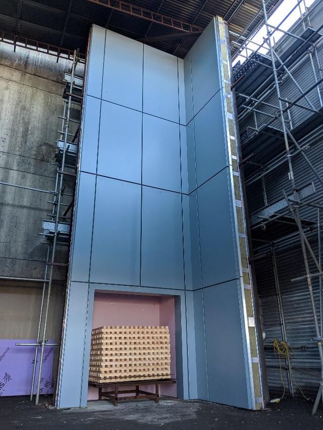
The design, installation, procurement and specification of the materials of the cladding system were
undertaken by the test sponsor. It was the responsibility of the test sponsor to ensure that all
components were install as per the manufacturer’s guidelines.
Figure 1 – Finished specimen prior to test
4.2.1 Measurements of system installed
Wall component Requirement for BS8414-2 Actual measurement
Width of main wall ≥ 2600mm 2810mm
Width of return wall ≥ 1500mm 1605mm
Combustion chamber opening 2000mm ±100mm 2120mm*
height
Combustion chamber opening 2000mm ±100mm 1980mm
width
Jamb of combustion chamber to 260mm ±100mm 329mm
the front face of return wall
*Lintel height raised to meet dimensions of prefabricated panels. Crib height and thermocouple locations adjusted
upwards, using the new lintel height as the datum point to suit.
Page - 11 - of 14Report Number/Version
Commercial in Confidence
FPA102034.002.135/4.0
5 Test results
Table 1 – System performance
Test criteria Requirement met/not met
System tested to full duration Requirement Met
External fire spread Requirement Met
Internal fire spread Requirement Met
5.1 Mechanical performance
5.1.1 Sheathing Board
Minor scorching was observed on the sheathing boards around the burn chamber opening, and
further small signs of heat damage were found further up the wall, however this was not found to
affect the structural integrity of the boards.
5.1.2 Cavity Barriers
The horizontal cavity barriers appeared to have operated as intended, preventing the vertical spread
of fire.
No flaming or fire spread was observed on the wing wall.
5.1.3 Insulation
Minor discolouration was observed on the rockwool insulation, however there was no evidence of fire
breaking through the insulation layer.
There was no evidence of the insulation contributing to the spread of fire.
5.1.4 Rails & Helping Hand Bracketry
The brackets and rails had melted away in the areas that suffered direct flame impingement from the
fuel source, however all other rails maintained structural integrity and none of façade panels became
loose or fell during the test.
5.1.5 Façade Panels
Initially the painted finish of the panels briefly flared up and then burned away, exposing the bare
aluminium. The aluminium then melted away in the regions that suffered direct flame impingement
from the fuel source.
Heat discolouration was noted on the panels above those that melted, as well as on the wing wall,
however all panels remained attached to the rails.
There was no evidence of the façade panels contributing to the spread of fire.
Page - 12 - of 14Report Number/Version
Commercial in Confidence
FPA102034.002.135/4.0
6 Classification and restrictions
6.1 Classification
The system described in this report has been tested and met the performance criteria set in BR
135:2013b.
6.2 Restrictions
• Following the at Grenfell Tower in 2017, testing, classification, regulation and recommendations
surrounding the testing and use of cladding materials on high rise buildings are all being
examined in the UK. As a result, the relevance of a successful BR135 classification report may
expire.
It is therefore recommended that the current regulatory climate should be assessed before a
successful BR135 classification report is relied upon as evidence of suitability.
The FPA test laboratory that issued the report will be able to offer assistance in this regard.
• This classification is valid only for the system described herein, installed and detailed.
• This classification report does not provide type approval for similar systems or for any individual
component parts that were used within the system tested.
b Annex A for BS8414-1 test or Annex B for BS 8414-2 test
Page - 13 - of 14Report Number/Version
Commercial in Confidence
FPA102034.002.135/4.0
7 References
[1] British Standards Institute, “BS 8414-2:2015+A1:2017, Fire performance or external cladding
systems - Part 2: Test method for non-loadbearing external cladding systems fixed to supported by a
structural steel frame,” British Standards Institute, London, 2017.
[2] S. Colewell and T. Baker, “BR135 Fire performance of external thermal insulation for walls of
multistorey buildings, Third Edition,” IHS BRE Press, Watford, 2013.
Page - 14 - of 14You can also read


