DPD Toolkit: Overview Background
←
→
Page content transcription
If your browser does not render page correctly, please read the page content below
DPD Toolkit: Overview
Background
Digital Predistortion technology (DPD) enables power-efficient transmission in modern wireless
communications systems. Prior to third generation (3G) cellular systems, wireless signals were
relatively benign in that their envelope (i.e. how the instantaneous size of the signal varies as it is
modulated with the digital data) was essentially constant. Subsequently (3G and beyond) the drive for
enhanced data capacity has resulted in the wireless signal envelope becoming increasingly noise-like.
This poses significant challenges for the transmitter and in-particular the power amplifier (PA).
Efficient power amplifiers tend to be non-linear, which is fine when the signal envelope is benign,
however the non-linear transmission of 3G/4G signals result in the generation of troublesome
interference, which can exceed regulatory requirements. To fix this there are essentially two options,
but only one practical choice:
Design a linear PA; such designs are expensive and highly inefficient (e.g. to transmit 20
Watts the PA would probably consume ~400 Watts or more). Or
Linearize the PA by a dynamic manipulation of the PA itself and/or its input signal. DPD is
a linearization technology which enables interference-free transmission using an essentially
non-linear (i.e. power efficient) PA.
Since 2008, drawing on over thirty years of transmitter product design expertise, Systems4Silicon has
supplied, supported and evolved its DPD technology to an international customer base. Development
of algorithms for DPD is complex, costly and time consuming and the resulting solution may put
significant demands upon the underlying signal processing resources. Systems4Silicon’s DPD Toolkit
is readily scaled to optimise these demands according to the needs of the customer’s system. It is
unique to the marketplace since it is delivered as IP cores for any ASIC or FPGA. Since Systems4Silicon
is independent of a device vendor this facilitates design migration between FPGA vendors’ devices
and from FPGA to ASIC.
S4S016_004 v0_3_0 Page 1 of 6
DPD Toolkit: Overview
Applications
The linearization of single or multi-carrier (mixed-mode) power amplifiers for contemporary
transmission standards such as LTE, WCDMA and DVB operating in either TDD or FDD mode. Since
the DPD IP is not specifically configured for the transmission standard it will also operate with legacy
and bespoke transmission technologies – please contact Systems4Silicon to discuss your specific
requirements.
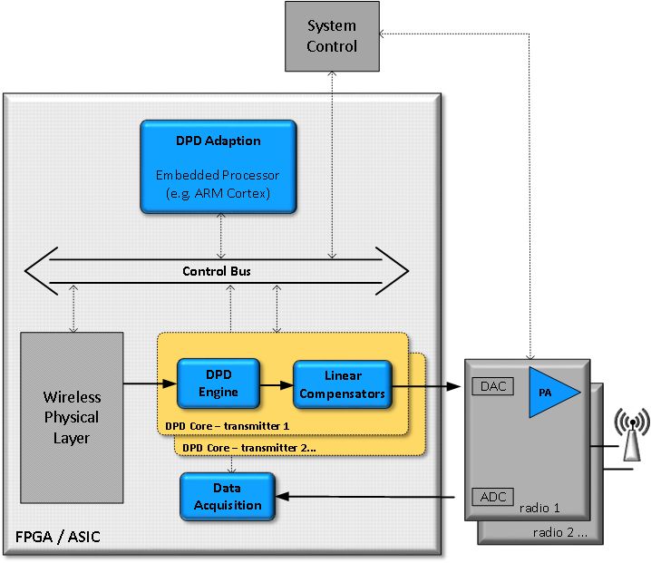
Figure 1 illustrates one example of how Systems4Silicon’s DPD Toolkit may be integrated within a
typical sub-system.
Figure 1: DPD Toolkit example sub-system architecture
Systems4Silicon’s DPD Toolkit comprises a DPD Adaption algorithm implemented in software and a
DPD Core which is targeted at the real-time hardware. The DPD Adaption algorithm is coded in
portable C for targeting at (for example) an FPGA soft-core processor, ARM Cortex hard processor or
other dedicated µP/DSP.
The DPD Core comprises the DPD Engine, transmit and observation path data capture functions and
linear distortion compensation for the analogue hardware. For platforms with analogue hardware that
S4S016_004 v0_3_0 Page 2 of 6DPD Toolkit: Overview introduces low levels of linear distortion the compensation function can be omitted to minimise total resource requirements. The DPD Core is implemented using a single clock domain and has fully deterministic sample latency. The user’s design should provide a robust crossing between this clock domain and any others within the design (e.g. data converter clocks). The DPD Adaption algorithm requires access to RAM for run-time data storage, however it can share the memory resources of the underlying hardware platform with customer applications. Typically, a hardware platform includes a controller unit1 for the configuration and control of platform peripherals such as data converters, analogue gain etc.; the same controller would be used to manage the operation of the DPD. During operation, in addition to the linearization function the DPD Adaption processing determines other correction values required to optimise system performance, for example transmitter gain and quadrature modulator compensation. These low-rate signals are communicated to the controller for application to the appropriate hardware actuator in the radio. Performance The screenshots in Figure 2 provide an illustration of the practical performance in relation to the improvement of unwanted spectral emissions. In both cases the PA is Doherty architecture and the waveforms exhibit a peak to average power ratio of ~10 dB. The left-had trace is illustrative of a mixed- mode UMTS and LTE transmission, whereas the other is single carrier LTE. Figure 2: DPD Toolkit illustrative performance 1 Which could be another embedded processor. S4S016_004 v0_3_0 Page 3 of 6
DPD Toolkit: Overview

Support
Systems4Silicon’s DPD Toolkit is supplied with a comprehensive engineering data sheet and test
benches. Additionally, for system integration there is a visualisation and analysis tool which provides
graphical performance and behavioural metrics for the linearized transmitter system (see
Figure 3). At the core of this system is a data logging facility, the file outputs of which may be analysed
locally by the system integrators or delivered to Systems4Silicon thereby enabling remote support.

Furthermore, Systems4Silicon will not simply deliver the IP and wave goodbye. The DPD component
is just one technology in a linearized transmitter system and within such systems, regardless of the
DPD supplier, both the radio and (more obviously) the PA itself impact on the overall attainable
performance. For example, the PA should be designed with linearization in mind and the radio
bandwidth must be suitable for the anticipated linearized performance. Such design decisions and
trade-offs are facilitated partly by the scalability of the DPD Toolkit solution, however, no less
important than this is the detailed engineering knowledge and dedicated support that is provided by
the Systems4Silicon team to help you attain the optimum performance for your system. Without such
support, a typical DPD IP “black box” can soon drag your system to the gloomy depths of
unexplainable behaviour. Systems4Silicon’s IP and dedicated support and knowledge transfer team
will not let you sink.

Figure 3: DPD Developer Assist integration support tool, example outputs

S4S016_004 v0_3_0                                                                             Page 4 of 6
DPD Toolkit: Overview

Features & Capabilities
       Feature                                                   Comment

Correction capability     Up to 30 dB or better ACLR improvement depending upon the DPD configuration
(non-linear)              and system specifications/characteristics.

Correction capabilities   Adaptive AQM dc-offset and imbalance correction.
(linear)
                          Adaptive gain and phase slope correction.
                          Adaptive gain control.

Supported transmission    Limited only by the capabilities of the FPGA/ASIC (i.e. the attainable system clock
bandwidth                 rate) and specification of the radio sub-system. State of the art with today’s FPGA
                          and data converter devices is approximately 100 MHz of modulation bandwidth.

Supported Tx channels /   Limited only by the capabilities of the FPGA/ASIC and specification of the radio sub-
MIMO                      system. Target technology system resources may be optimised by commutating the
                          use of the DPD’s Data Acquisition sub-system and the Adaption Processor between
                          multiple channels. The JESD204B and gigabit transceiver capabilities of today’s
                          FPGAs combined with modern converter devices mean that device pin-out
                          restrictions are far less likely to be a limiting factor for multiple channel support.

PA technology             Agnostic with respect to PA transistor technology or PA topology (e.g. GaS, GaN,
                          LDMOS, Doherty, Class A/B, Envelope Tracking, …)

Transmission standards    Agnostic with respect to transmission standard (e.g. WCDMA, LTE, DVB) and air
                          access technique (e.g. FDD/TDD), including multi-carrier and mixed mode operation.

DPD update cycle          Better than 100 ms for a single channel system. Rapid convergence algorithms result
period                    in system ACLR typically better than 1 dB of nominal minimum within 2-3 update
                          cycles.

Memory correction         Scalable as demanded by the PA characteristics.

PA efficiency             This is not a valid metric for any DPD implementation. Typically a PA will be
improvement               designed to meet a particular efficiency and then the DPD enables linear behaviour at
                          that efficiency. If, in order to meet spectral emissions, the drive to a particular PA has
                          had to be reduced then the DPD will help to recover the original operating power
                          level and hence efficiency. If the PA has been over-designed for the target operating
                          power then the DPD may enable the output power and efficiency to be increased
                          whilst maintaining linear transmission.

Convenience               In-deployment algorithmic training or calibration is not required, either at power-up
                          or subsequently.

Crest Factor Reduction    Crest Factor Reduction (CFR) and DPD are different yet complimentary technologies
(CFR)                     that both facilitate the enhancement of PA efficiency. Although often used together
                          for optimum efficiency, this is a system design decision and not mandatory.
                          Systems4Silicon’s DPD operates with or without a preceding CFR function.

S4S016_004 v0_3_0                                                                                      Page 5 of 6
DPD Toolkit: Overview
Target Device Resources
In addition to the DPD IP being scalable according to the application, the implementation is already
extremely compact. Table 1 illustrates the resource utilisation for a typical implementation on Altera
Arria 10 of a single channel system that includes comprehensive memory correction capabilities
necessary for broadband operation. Should the embedded Cortex MPCore or an external processor be
available then it can be seen that the demands upon the device fabric become very small indeed.
Table 1: DPD Toolkit resource utilisation for Altera Arria 10 part number 10AX048
ALUTs Dedicated logic DSP block Block Memory
registers multipliers Kbits
DPD Adaption (Nios II/f) 8,000 8,250 13 230
DPD Core and Data
2,800 4,850 46 224
Acquisition
Total 10,800 13,100 59 454
Utilisation (using Nios II) < 5.9% < 1.8% < 2.2% < 1.4%
Utilisation (using Cortex
MPCore or an external < 1.6% < 0.7% < 1.7% < 0.7%
processor)
Availability
Systems4Silicon’s DPD Toolkit IP is immediately available for FPGA and ASIC targets together with
an Engineering Data Sheet, comprehensive test bench support and integration tools. To discuss your
specific implementation requirements please contact Systems4Silicon (details below).
Contact
For information contact Richard Hewitt, Chief Technology Officer at Systems4Silicon:
UK: +44 (0)7968 162 306
Web: www.systems4silicon.com
Email: rhewitt@systems4silicon.com
All information contained within this technical note is
subject to change without notice.
S4S016_004 v0_3_0 Page 6 of 6You can also read