TEST PROTOCOL - BLIND SPOT VISUALIZATION - Asean Ncap
←
→
Page content transcription
If your browser does not render page correctly, please read the page content below
TEST PROTOCOL –
BLIND SPOT VISUALIZATION

         Version 1.0
       November 2019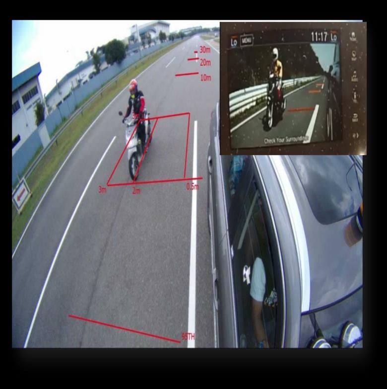
Preface

Where text is contained within square brackets, this
denotes that the procedure being discussed is currently
being trialled in ASEAN NCAP. Its incorporation in the
Test Protocol will be reviewed at a later date.

During the test preparation, vehicle manufacturers are
encouraged to liaise with the laboratory and to check that
they are satisfied with the way cars are set up for testing.
Where a manufacturer feels that a particular item should
be altered, they should ask the laboratory staff to make any
necessary changes. Manufacturers are forbidden from
making changes to any parameter that will influence the
test, such as dummy positioning, vehicle setting,
laboratory environment etc.

It is the responsibility of the test laboratory to ensure that
any requested changes satisfy the requirements of ASEAN
NCAP. Where a disagreement exists between the
laboratory and manufacturer, the ASEAN NCAP
secretariat should be informed immediately to pass final
judgement. Where the laboratory staff suspect that a
manufacturer has interfered with any of the setup, the
manufacturer's representatives should be warned that they
are not allowed to do so themselves. They should also be
informed that if another incident occurs, they will be asked
to leave the test site.

Where there is a recurrence of the problem, the
manufacturer’s representatives will be told to leave the
test site and the Secretariat should be immediately
informed. Any such incident may be reported by the
Secretariat to the manufacturer and the persons concerned
may not be allowed to attend further ASEAN NCAP tests.

DISCLAIMER: ASEAN NCAP has taken all reasonable
care to ensure that the information published in this
protocol is accurate and reflects the technical decisions
taken by the organisation. In the unlikely event that this
protocol contains a typographical error or any other
inaccuracy, ASEAN NCAP reserves the right to make
corrections and determine the assessment and subsequent
result of the affected requirement(s).

In addition to the settings specified in this protocol, the
following information will be required from the
manufacturer of the car being tested in order to facilitate
the vehicle preparation. A vehicle handbook should be
provided to the test laboratory prior to preparation.
TEST PROTOCOL –
              BLIND SPOT VISUALIZATION

                          Table of Contents

1 INTRODUCTION ........................................................ 2
2 DEFINITIONS .............................................................. 3
3 REFERENCE SYSTEM ............................................... 4
4 MEASURING EQUIPMENT ....................................... 4
5 TEST CONDITIONS.................................................... 7
6 TEST PROCEDURE .................................................... 8
ANNEX A……………………………………………..14

                                      1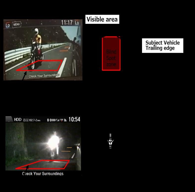
NEW CAR ASSESSMENT PROGRAM FOR
       SOUTHEAST ASIAN COUNTRIES
              (ASEAN NCAP)

               TEST PROTOCOL –
           BLIND SPOT VISUALIZATION

1    INTRODUCTION
Each year, passenger vehicles are fitted with new
innovative mechanical and electronic features to enhance
drivability and safety. The Blind Spot Technology (BST)
systems are an example of such features. BST can be
categorized into two types; detection and non-detection.
The detection type refers to BSD (Blind Spot Detection
system), whereas non-detection type refers to BSV (Blind
Spot Visualization system).

BSD uses sensors to detect one or more vehicles in
adjacent lanes that may not be directly observable by the
driver. The system warns the driver of the approaching
vehicle to help facilitate safe lane changing.

Not all BST have the same detection capabilities or
operating conditions. In the vehicle owner’s manuals,
many automotive manufacturers state that their systems
are designed to detect only highway vehicles, not other
objects including bicycles, motorcycles, humans, or
animals. Various systems have a threshold speed whereby
if the speed of the equipped vehicle is below the threshold
speed, typically ranging from 5 to 20 km/h, the system is

                            2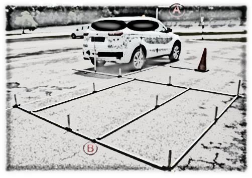
inactive. BSV displays image according to the driver’s
operation from 0 km/h to the maximum speed.

2   DEFINITIONS
Throughout this protocol the following terms are used:

2.1 Subject vehicle (SV)
Vehicle equipped with the system in question and related
to the topic of discussion

2.2 Target vehicle (TV)
Motorcycle that is closing in on the subject vehicle from
behind, or any vehicle that is located in one of the adjacent
zones

2.3 Coverage zone
Entire area to be monitored by a BST, a system’s coverage
zone consisting of a specific subset of the following zones:
left adjacent zone, right adjacent zone, left rear zone and
right rear zone

2.4 Adjacent zones
Zones to the left and right of the subject vehicle

2.5 Visualization function
As for non-detection type, the system shall be able to
provide a live visual of the vehicles moving in the same
direction, and on the side and/or rear of the subject vehicle
which can be activated manually or via turn signal action.

NOTE: A target vehicle located within the coverage zone
will thus be visualized by the system.

                             3
3    REFERENCE SYSTEM
The International Standard specifies the system
requirements and test methods for Lane Change Decision
Aid Systems (LCDAS) LCDAS are fundamentally
intended to warn the driver of the subject vehicle against
potential collisions with vehicles to the side and/or to the
rear of the subject vehicle, and moving in the same
direction as the subject vehicle during lane change
maneuvers. Hence, the detection and visualization
technology will reduce motorcyclist injuries and deaths in
Southeast Asia.

3.1     Type I systems
These systems shall provide the blind spot warning
function only. They are intended to warn the subject
vehicle driver of target vehicles in the adjacent zones.
They are not required to provide warnings of target
vehicles that are approaching the subject vehicle from the
rear. The subject vehicle driver shall be made aware of the
limitations of such systems, at least in the owner’s manual.
In particular, the owner’s manual shall include the
following statement: “This system provides support only
within a limited area beside the vehicle. The system may
not provide adequate warning for vehicles approaching
from the rear.”

4    MEASURING EQUIPMENT
The basic measurements include video logger and
performance meter for event recording, turn signal
indicators and BSV live visual system.

                             4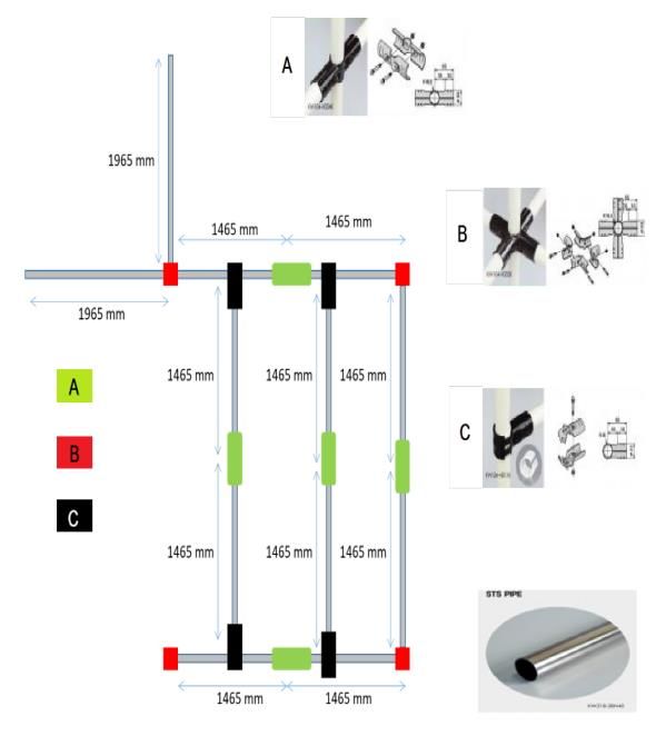
4.1 Zone Instrumentation

4.1.1 Blind Spot Technology (BST) assessment jig
The setup process includes preliminary plotting of blind
spot zone, fitment angle of video logger and performance
meter camera and onboard equipment. Precise and
accurate measurement is essential to ensure the superiority
and reliable output from the assessment.

Referring to Figure 1-1 below, BST jig setup is divided
into two parts which are part A and B.

            Figure 1-1: Blind spot zone setup

Part A is a video logger jig frame for outside camera and
is located on the top side of main windshield.

Part B is a jig for pre-setup of blind spot zone level 3 for
viewing in live-feed video recording taken by the video
logger and performance meter.

                             5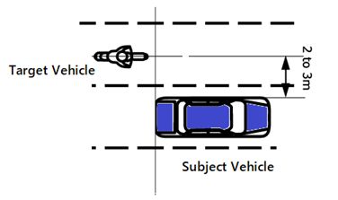
The assessment will be based on video recording system
using video logger and performance meter applications
which require pre-setup of zone area level 3 in the live-
feed view. These two parts are designed to be used in any
passenger car and is removeable with static measurement
at any flat surface.

As shown in Figure 1-2, the four main components to
complete the jig structure include:

•      Component A - Black metal connector pipe C1-24
(Length 130mm x diameter 33mm x hollow 38mm) x 5
pcs.
•      Component B - Black metal connector pipe C2-5
(Length 130mm x diameter 33mm x hollow 33mm) x 4
pcs.
•      Component C - Black metal connector pipe C3-11
(Length 84mm x diameter 33mm x hollow 36mm) x 4 pcs
and the last component is a standard steel pipe (diameter
28mm) with 2 different length 1465mm (10 pcs) and
1965mm (2 pcs).

The tools required for setup process include: Allen-key
size 3mm to tighten the connector and aluminium hollow
pipe.

                           6
D
D
Figure 1-2: Blind spot coverage zone jig
5 TEST CONDITIONS
The test location shall be on a flat, dry asphalt or concrete
surface. The ambient temperature during testing shall be
within the range of 5 °C - 40 °C. The test shall be
conducted during the day and at night (without street lamp
or any other lamp).
75.1 Test Track
5.1.1 Conduct tests on a dry (no visible moisture on the
surface), uniform, solid-paved surface with a consistent
slope between level and 1%.
5.1.2 The surface must be paved and may not contain any
irregularities (e.g. large dips or cracks, manhole covers or
reflective studs).
6 TEST PROCEDURE
6.1 Conditioning
6.1.1 General
A car (test vehicle) is used as delivered to the laboratory.
There is no restriction on car selection.
6.1.2 Vehicle Preparation
Setup the on-board test equipment and instrumentation in
the vehicle. Also fit any associated cables, cabling boxes
and power sources.
6.1.3 Test Target Vehicle
The main objective of BST testing is to check the
functionality of BST with regard to visibility of
motorcycles which is a prevalent issue in the ASEAN
region.
Thus, the dimension of target vehicle used in this protocol
will be as follows:
8Table 1.0 Target vehicle dimension
Dimension (m)
Length 1.8 to 2.0
Width 0.6 to 0.8
Height 1.0 to 1.4
6.2 Test Conduct
6.2.1 Static straight-lane Tests
The test SV is subjected to one type of performance tests
namely static straight-lane tests.
In the static straight-lane test series, both SV and TV are
placed on separate but parallel lanes with the target vehicle
positioned in the lane next to the SV either on the driver
or passenger side as depicted in Figure 3-1.
9Figure 3-1: Target Vehicle and Subject Vehicle position
The static straight-lane tests are performed on a controlled
straightaway test facility containing equal or more than
three parallel lanes of concrete surface roadway. All tests
are performed during the day or/and at night.
Once these measurements are completed for the
passenger-side, the entire test is repeated for the driver-
side sensor.
*In order to identify the system’s interaction with the
application of the SV’s turn signals, the test series are
repeated with the turn signal activated.
Note: Manufacturer is required to provide information for
specific model.
106.2.2 Functionality Check and Scoring
Check the functionality whether the BSV system provides
adequate live visual of static vehicle when test is
performed according to the test procedure with the target
vehicle described in the 6.2.2.1.
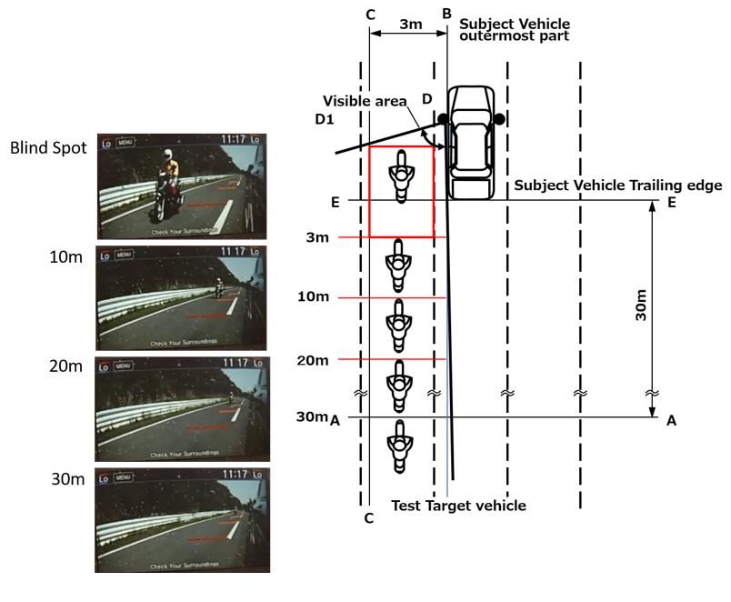
6.2.2.1 Static test
In the static test, the target vehicle will be positioned at 5
different locations in the lane next to the subject vehicle in
between 2 to 3 meters adjacent as described in Figure 3-2.
Confirm that the target vehicle is visible at each place and
distance.
The locations of target vehicle must be as follows (in
respect to subject vehicle rear);
a) 30m zone
b) 20m zone
c) 10m zone
d) 3m zone, and
e) Blind spot zone
For BSV type system, the system must be able to provide
a live visual of the static vehicle in the same direction, and
on the adjacent side of the subject vehicle. The result
should be based on the following Table 1.1.
11Table 1.1: BST Visualization type requirements
Live visual video Must be clearly visible
In 30-meter zone from SV trailing
Distance
edge to blind spot zone
Figure 3-2: Functionality check and score
If the subject vehicle does not meet all the requirements
as described in Table 1.1, no point will be rewarded.
12The subject vehicle should be able to visualize other
vehicles in the blind spot zones, especially smaller ones
such as motorcycles (target vehicle) and provide adequate
visibility as described in Figure 3-3.
Figure 3-3: Zone requirements for BSV system live
visual
*For assessment at night, the test needs to be conducted
with a motorcycle with the head-light turned on.
Note: If required by ASEAN NCAP inspector.
13ANNEX A
A.1
Figure 4-1: Video logger image of BSV test
14A.2
Figure 4-2: Blind Spot Zone
15Editors
Ir. Dr. Khairil Anwar Abu Kassim (Adjunct. Prof)
Malaysian Institute of Road Safety Research (MIROS)
Yahaya Ahmad
Malaysian Institute of Road Safety Research (MIROS)
Mohd Hafiz Johari
Malaysian Institute of Road Safety Research (MIROS)
Salina Mustaffa
Malaysian Institute of Road Safety Research (MIROS)
1617
You can also read