Vehicle Dynamics through Multi-body dynamics - Altair ...
←
→
Page content transcription
If your browser does not render page correctly, please read the page content below
Vehicle Dynamics through Multi-body
dynamics
Introduction
Competitive motorsport at any level is a matter of the final 0.1%. What is meant by that is the
winner will be only a faction better than the person who comes second and any competitive edge
gained (even 0.1%) might be the difference between winning and losing.

Vehicle handling can play a crucial role in gaining this edge. The Dynamic events are designed to test
the handling characteristics of the vehicle to the last detail. Clever vehicle handling design stems
from strong understanding of vehicle dynamics. Multi-body dynamics simulation through Motion
View and Motion Solve is a strong tool to help students and professionals alike to validate and test
out their vehicle dynamics knowledge and vehicle design.

Tyres and rubber
Introduction
Any lecture/presentation/training talking about vehicle dynamics will start with a discussion about
tyres. Tyres are the mechanical link between the vehicle and the road. Every non-aerodynamic force
and moment that acts on the vehicle will be through the tyre and understanding the functioning of
tyres is the key in understanding the dynamics of the vehicle.

Tyres are complicated rubber interfaces with the road. Multi-body dynamics, can involve
computations of detailed mathematical models of the tyre. Fortunately we can develop our
understanding with simple ideas about the tyre “contact patch” and later move on to more
complicated mathematical tyre models.

The contact path
Tyres work because of rubber friction. The normal load applied by the weight of the vehicle deforms
the rubber. There is a flattened piece of rubber in contact with the road which is called the “contact
patch”. The contact patch is where all the tyre forces act. The rubber in contact with the road pushes
on the road and static friction between the rubber in the contact patch and the road is responsible
for the tyre force.

Frictional forces have their limits beyond which the rubber would start to slide and a lesser (than
peak static friction force) frictional for will be applied at the contact patch. This is when the vehicle
tyres at beyond their limits, slide around and the driver losses control. The maximum tyre force is
also called “available tyre grip”. For maximum performance it is desirable that the tyre forces stay at
the maximum grip levels while not sliding. When the tyre is sliding the driver has little control over
the vehicle and the maximum force generated is less than the peak force when the contact patch is
not sliding.
Friction Circle
It is important to understand that the tyre force produced by friction is resolved into 2 significant
components. They are –
Longitudinal force
The force applied in the direction that corresponds to “straight ahead” for the tyre. This
force is responsible for the acceleration and braking forces that are produced by the tyre.
Lateral Force
The force applied in the direction of the spin axis of the wheel. This force is responsible for
the steering (lateral) forces which enable a vehicle to make a corner or turn.
It is important to note that these are components of the forces so they do not have independent
peak (maximum) force values, the overall force has a peak value at a given vertical load. This implies
that if the tyre at a given point of time is producing peak longitudinal force its peak lateral force
producing capacity is very close to zero and vice-versa. More generally, more the lateral force a tyre
is generating the peak longitudinal force comes down.
This can be graphically plotted as a plot of peak lateral force at different longitudinal force values.
This plot forms a closed loop and is popularly known as the tyre friction circle. The tyre is considered
to be on the limit when the point corresponding to the current lateral and longitudinal force
produced by the tyre is on the boundary of this loop. If the point is inside it means that there can be
more force (lateral or longitudinal) drawn, and if the point is outside it means that the contact patch
is sliding.Tyre Friction Circle
Max Accel Force
Max Lateral Force Max Lateral Force
Max Brake Force
Note: Usually the peak longitudinal force at zero lateral force is not the same as peak lateral force at
zero longitudinal force. So the friction circle is more of a friction oval or a friction egg.
Understanding Vehicle Handling
The handling characteristics of the vehicle are also the function of the tyre force limits. If the front
tyres reach their limit before the rear tyres the vehicle will “understeer” while if the rear tyres
approach their limit before the fronts the vehicle will “oversteer”. Making the vehicle handle better
involves doing 2 major things –
Improve the “quality” of the contact patch to maximise grip available
To maintain a balance between the combined grip levels for the front wheels and the
combined grip levels of the rear wheels.
Typically in the design of the student competition vehicle, initially the front suspension of the vehicle
is designed separately from the rear. During this phase half car models (front half and rear half) are
built for simulation and focus is on the improvement of the quality of the contact patch.
Later the front half and the rear half car models are built up as one and the balance of the vehicle is
improved.
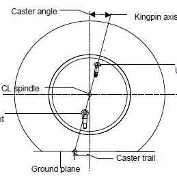
Wheel Alignment
While designing suspensions there is often talk about wheel orientations. Terms like caster, camber
and toe feature often as referred to during vehicle design. Here is a brief introduction of each term
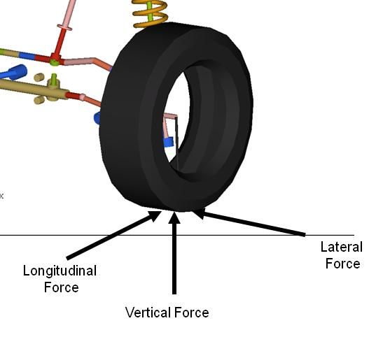
as per WikipediaCamber Camber angle is the angle made by the wheels of a vehicle; specifically, it is the angle between the vertical axis of the wheels used for steering and the vertical axis of the vehicle when viewed from the front or rear. It is used in the design of steering and suspension. If the top of the wheel is farther out than the bottom (that is, away from the axle), it is called positive camber; if the bottom of the wheel is farther out than the top, it is called negative camber. Toe Toe angle is the symmetric angle that each wheel makes with the longitudinal axis of the vehicle, as a function of static geometry, and kinematic and compliant effects. This can be contrasted with steer, which is the anti- symmetric angle, i.e. both wheels point to the left or right, in parallel (roughly). Positive toe, or toe in, is the front of the wheel pointing in towards the centreline of the vehicle. Negative toe, or toe out, is the front of the wheel pointing away from the centreline of the vehicle. Toe can be measured in linear units, at the front of the tire, or as an angular deflection. Caster Caster angle or castor angle is the angular displacement from the vertical axis of the suspension of a steered wheel in a car, bicycle or other vehicle, measured in the longitudinal direction. It is the angle between the pivot line (in a car - an imaginary line that runs through the centre of the upper ball joint to the centre of the lower ball joint) and vertical. Car racers sometimes adjust caster angle to optimize their car's handling characteristics in particular driving situations. Significance of wheel alignment Wheel alignment determines how the tyre is in contact with the road, hence severely impacts the quality of the contact patch. All the parameters are equally important but for the purpose of this document we will talk only of camber. Camber Effects on Contact Patch A tyre is designed to run perfectly vertical with respect to the road. This is usually the situation when maximum grip is available. Any tilt in the tyre will reduce the grip. How much the grip will reduce by is a function of the tyre design and construction. The reason for this is that the upright tyre has a uniform contact patch, in other words the pressure distribution in the deformed area is uniform. This ensures a large portion of the rubber is in contact with the surface and most of the rubber is producing static friction. When the pressure in the contact patch is uneven as the tyre nears the limits of its grip levels, some portion of the contact patch that is experiencing low pressure will start sliding, lowering grip levels.
P                                      P

                                  Pressure Distribution Across Contact Patch

Therefore it is safe to conclude that it is in the best interest of the designer to keep the camber at
zero irrespective of the suspension travel. It is important to understand that is with respect to the
road and not the chassis.

Camber Change with Wheel Travel
Depending on your suspension geometry, camber of the wheel will tend to change with wheel
travel. Understanding this is one of the key aspects to understanding vehicle suspension design.
Multi-body Dynamics simulations through Motion View and Motion Solve can be a powerful tool to
visualise, analysis and optimise the change in camber along with other suspension parameters.

The suspension can be thought of a kinematic mechanism where the wheel is one of the links. The
chassis is the ground body and all observations are made with respect to the chassis, making it easy
to visualise. For this the concept of Instant Centres must be revisited.

Instantaneous centre (IC)
Instantaneous Centre (sometimes called Instant Centre) is a more general concept but with respect
to suspension design it is the virtual point about which the wheel appears to rotate with respect to
the chassis when there is wheel travel (Suspension moves up or down).

The instantaneous centre (IC) is the location found by the virtual intersection of the suspension links
when projected on to a two dimensional plane. The suspension when projected on to the two
dimensional plane rotates about this location.

The front view instantaneous centre is the virtual intersection of the suspension links when
projected onto the front view plane. Therefore for an observer sitting in the chassis the wheel will
appear to rotate about the Instant Centre as it moves up or down due to suspension travel.

It is important to remember that for most suspension types the IC keeps moving around with
suspension travel and is not constant. Also, if the two suspension links are parallel the IC is at infinity
and there will be no rotation of the wheel with respect to the chassis with wheel travel.
The rotation of the wheel with respect to the chassis directly affects the orientation of the wheel with respect to the road. Then the vehicle hits a bump both the wheels travel up together with respect to the chassis and when the vehicle rolls one side moves up and the other moves down. As these movements happen, the camber of the wheel changes with respect to the road. The plot of the camber with respect to the road verses vehicle roll and wheel travel in bump are popularly known as Camber Curve. Demonstration of effects of the Camber Curve First let us consider the situation where the suspension is designed such that the Instant centre is at infinity. This means that the camber gain in bump is zero. That is, when the wheel moves up and down with respect to the chassis the wheel still stays upright. In this situation let us look at the situation where the vehicle is braking. Braking causes the vehicle to pitch forward (dive). It’s easy to notice this while driving any car or while observing a car come to a stop. This pitching causes the body or the chassis of the vehicle to dip in the front. This lowering of the chassis with respect to the wheels will cause the wheel to rotate about the IC, but since the IC is at infinity there is no rotation and hence no camber gain.
This is a very desirable situation. The car is optimised in terms of camber gain to handle braking
manoeuvres, the wheels stay upright, the contact patch is still flat on the road and maximum
longitudinal force is available for breaking.

Now let us consider the same car while cornering. The vehicle will roll while cornering. This means
that with respect to the chassis one of the wheels will go up and the other down depending on the
cornering direction. With respect the chassis the wheel is still upright.

                                       Cornering direction

In reality of course the inner tyre does not go below the ground and the outer tyre above, the car
chassis is rotated. On the road the cornering situation looks like this
Cornering direction
Both the wheels are not upright with respect to the load. This will reduce the maximum lateral force
that the tyres can produce. The maximum speed at which the vehicle can turn a corner of a certain
radius will be lesser than the situation where the wheels would have been upright.
Suppose we want to design a vehicle which is good at cornering, then we need to make sure that the
IC of the suspension would not be at infinity. We need to make sure that the IC is such that the
wheel rotates around an arc relative to the chassis as it moves up or down.
Arc of rotation of
wheel
Instant Centre
In this situation during roll the wheels will still stay upright. This is very desirable as now during
cornering the wheels can provide maximum grip. This will greatly improve the maximum speed at
which a vehicle can make a corner.Again, in the roll situation the wheels are actually on the ground and the chassis rotates, so the camber is still zero with respect to the road. As the next diagram illustrates – Now let us observe what happens if we look at the same suspension configuration during braking and other straight line events.
We observe that now during the braking manoeuvre when the both the wheels move up with
respect to the chassis. The wheels rotate with respect to the chassis such that they maintain the
defined arch. This causes the wheels to be tilted with respect to the road and thereby reducing the
maximum available grip in the braking and acceleration.

This means that neither of the 2 suspension configuration is the correct solution and a compromise
needs to be found. A parallel configuration of the control arms will cause the vehicle to perform
better in straight line events and the IC close to the centre of the vehicle will improve the cornering
speeds but have an adverse effect on braking performance. The correct compromise is a designer
choice based on a lot of factors which include expected terrain, performance strengths of the car,
driver preference, etc.

Multi-Body Dynamics Simulations
Multi-body Dynamics Simulations using Motion View and Motion Solve are a powerful tool to
visualise and analyse these suspension parameters. Camber Curves and other related information
can be obtained by running half car simulations on a suspension models. Roll analysis and ride
analysis will give accurate camber cures for both the situations. More information about how to
conduct these simulations is available in the Half Car Analysis user guide.

The example here is just one of the design decisions and trade-offs that need to be made. Many
similar trade-off decisions can be significantly aided by MBD simulations.
You can also read