Composite-ARF Extra 330L, 2 x 2m - Instruction Manual - Composite-ARF Extra 330L(2 x 2m)
←
→
Page content transcription
If your browser does not render page correctly, please read the page content below
Composite-ARF Extra 330L (2 x 2m)   techsupport@composite-arf.com

                    Instruction Manual
  Composite-ARF Extra 330L, 2 x 2m

TAVS Technology                                       version 1.0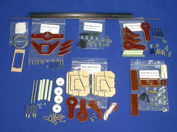
Composite-ARF Extra 330L (2 x 2m)                               techsupport@composite-arf.com

      Instructions for Extra 330L IMAC-Airplane
Thank you very much for purchasing our Composite-ARF Extra 330L all composite aircraft, made
with the revolutionary Total Area Vacuum Sandwich (TAVS) technology

Before you get started building and setting-up your aircraft, please make sure you have read this
instruction manual several times, and understood it. If you have any questions, please don’t
hesitate to contact us. Below are the contact details:

Email:                feedback@composite-arf.com
or                    techsupport@composite-arf.com
Telephone:            Phone your C-ARF Rep!!! He will be there for you.
Website:              http://www.composite-arf.com

               Liability Exclusion and Damages
You have acquired a kit, which can be assembled into a fully working R/C model when fitted out
with suitable accessories, as described in the instruction manual with the kit.

However, as manufacturers, we at Composite-ARF are not in a position to influence the way you
build and operate your model, and we have no control over the methods you use to install,
operate and maintain the radio control system components. For this reason we are obliged to
deny all liability for loss, damage or costs which are incurred due to the incompetent or incorrect
application and operation of our products, or which are connected with such operation in any
way. Unless otherwise prescribed by binding law, the obligation of the Composite-ARF compa-
ny to pay compensation is excluded, regardless of the legal argument employed.

This applies to personal injury, death, damage to buildings, loss of turnover and business,
interruption of business or other direct and indirect consequent damages. In all circumstances
our total liability is limited to the amount which you actually paid for this model.

 BY OPERATING THIS MODEL YOU ASSUME FULL RESPONSIBILITY FOR YOUR ACTIONS.

It is important to understand that Composite-ARF Co., Ltd, is unable to monitor whether you
follow the instructions contained in this instruction manual regarding the construction, operation
and maintenance of the aircraft, nor whether you install and use the radio control system
correctly. For this reason we at Composite-ARF are unable to guarantee, or provide, a
contractual agreement with any individual or company that the model you have made will
function correctly and safely. You, as operator of the model, must rely upon your own expertise
and judgement in acquiring and operating this model.

                   Supplementary Safety Notes
Pre-flight checking:
Before every session check that all the model’s working systems function correctly, and be sure
to carry out a range check.
The first time you fly any new model aircraft we strongly recommend that you enlist the help of
an experienced modeller to help you check the model and offer advice while you are flying.

                                                2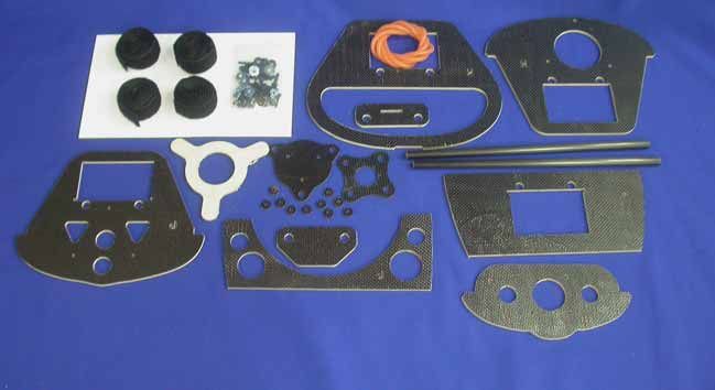
Composite-ARF Extra 330L (2 x 2m)                                 techsupport@composite-arf.com

He should be capable of detecting potential weak points and errors. Be certain to keep to the
recommended CG position and control surface travels. If adjustments are required, carry them
out before operating the model. Be aware of any instructions and warnings of other manufactur-
ers, whose product(s) you use to fly this particular aircraft, especially engines & R/C equipment.
Please don’t ignore our warnings, or those provided by other manufacturers. They refer to things
and processes which, if ignored, could result in permanent damage or fatal injury.

                                         Attention !
This IMAC-Aircraft is a high-end product and can create an enormous risk for both pilot and
spectators, if not handled with care, and used according to the instructions. Make sure that you
operate your Extra according to the AMA rules, or those laws and regulations governing model
flying in the country of use.

The engine, servos and control surfaces have to be attached properly. Please use only the
recommended engines, servos, propellers, and accessories. Make sure that the ‘Centre of
Gravity’ is located in the recommended place. Use the nose heavy end of the CG range for your
first flights. A tail heavy plane, in a first flight, can be an enormous danger for you and all spec-
tators. Fix any weights, and heavy items like batteries, very securely into the plane.

Make sure that the plane is secured properly
when you start up the engine. Have a helper hold
your plane from the tail end or from behind the
                                                                         NO !!!
wing tips before you start the engine. Make sure
that all spectators are behind, or far in front, of the
aircraft when running up the engine.                      NO                                    NO

Make sure that you range check your R/C system
thoroughly before the 1st flight. It is absolutely
necessary to range check your complete R/C                                          Secure the plane
installation first WITHOUT the engine running.                                        before starting
Leave the transmitter antenna retracted, and DANGER ZONES                                the engine.
check the distance you can walk before ‘fail-safe’
occurs. Then start up the engine, run it at about
half throttle and repeat this range check with the engine running. Make sure that there is no
range reduction before ‘fail-safe’ occurs. Only then make the 1st flight. If the range with engine
running is less then with the engine off, please contact the radio supplier/engine manufacturer
and DON’T FLY at that time.

Check for vibrations through the whole throttle range. The engine should run smoothly with no
unusual vibration. If you think that there are any excessive vibrations at any engine rpm’s, DON’T
FLY at this time and check your engine, spinner and propeller for proper balancing. The light-
weight sandwich composite parts don’t like too much vibration and they can suffer damage. The
low mass of all the parts results in a low physical inertia, so that any excess vibrations can affect
the servos and linkages.

Make sure that your wing and stab spar tubes are not damaged. Check that the anti-rotation pins
for the wings and stabiliser are not loose. Check that the plastic wing retaining nuts are tight, that
the M3 bolts retaining the horizontal stablisers onto the carbon tube are tight, and that the rud-
der hinge wire cannot come out with a piece of clear tape.

                                                    3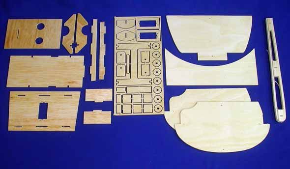
Composite-ARF Extra 330L (2 x 2m)                                  techsupport@composite-arf.com

           General information about
  fully-composite aircraft structure and design
All the parts are produced in negative molds, manufactured using vacuum-bagged sandwich
construction technology. All parts are painted in the moulds, either single colour or designer
colour schemes. A new production method, called TAVS (Total Area Vacuum Sandwich), enables
us to present this aircraft with incredible built-in strength, while still being lightweight, and for a
price that nobody could even consider some years ago. This production process has huge
advantages, but a few disadvantages as well. These facts need to be explained in advance for
your better understanding.

Description of Parts
The Wings:
Both wing halves are made in negative moulds, and fully
vacuum bagged, using only 2 layers of 2 oz. cloth in com-
bination with a very hard 2 mm foam sandwich form a hard
and durable outer skin.

The ailerons are hinged already for you - laminated in the
mould and attached to the wing with a special nylon hinge-
cloth, sandwiched between the outer skin and the foam.                       Centreline of hinge axis
This nylon hinge is 100% safe and durable. You will never
have to worry about breaking it, or wearing it out. There is
no gap at all on the top wing surface, and there is a very
narrow slot in the bottom surface, where the aileron slides
under the main wing skin during down throw. This means                      Phenolic control horn
that the hinge axis line is on the top surface of the wing, not
in the centre. This is NOT a disadvantage, if you program
in about 10% NEGATIVE aileron differential in your transmitter. This means that the ‘down’ throw
needs to be about 10% more than the up throw. Why? Because the axis of the hinge is not at
the centreline of the aileron, so it moves slightly in and out when operated, and the aileron gets
a little "bigger" in surface area when moving up, and "smaller" when moving down.

The bottom slot needs some explanation, too. The cut line is exactly in the correct position so
that the aileron slides under the wing skin smoothly. If the cut was a few mm forward or back, it
would not work properly. So, make sure that the lip is not damaged, and that the aileron slides
under this lip perfectly. It will NOT lock at any time, if lip is not damaged. If damage occurs to the
lip, you can cut off 2-3 mm, but you should NEVER need to cut off more than this.

The Fuselage:
The fuselage is also made in negative moulds, constructed using TAVS technology. The main
internal parts for the landing gear, wing and stab spar supports are glued in during manufacture,
to ensure accurate location and reduce the assembly time for you. There is no need to even
check the incidences - you can be assured that these are already set in the moulds so that no
adjustment is necessary.

The landing gear mount is strong and doesn’t need any extra reinforcement. You have an
extremely light weight fuselage, and the gear loads need to be led into the structure gently. The
landing gear is a fairly flexible design, which works very much like shock absorbers. This plane

                                                  4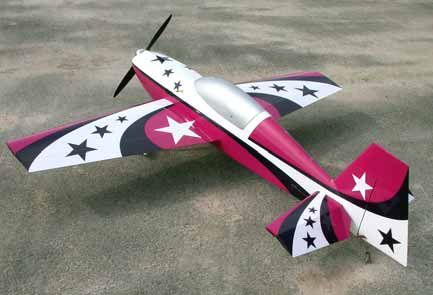
Composite-ARF Extra 330L (2 x 2m)                               techsupport@composite-arf.com

is not made for crashing, but the landing gear will take
some hard landings without problems. Do not change or
modify it, as the results would only be negative. We had
plenty of time and experience to engineer the strength
needed in this area - and we did !

The Stabilisers:
The stabiliser parts are also vacuum bagged sandwich.
The elevator control surfaces are elastic-hinged, and the
rudder is hinged with a 2mm Ø steel wire, fitted through
phenolic hinge bearing plates, allowing perfect alignment.

The rudder & elevator design gives at least 45 degrees
throw. The horizontal stabs are mounted on a 14mm car-
bon tube and one 6mm Ø glassfibre anti-rotation pin each,
and controlled by one powerful servo installed in the fuse-
lage for each elevator. Please remember during assembly
of the plane to save every gram of weight in the tail area.
The rudder is adequately powered by a single JR8411
servo in the fuselage with a closed-loop system.

Take Care:
Composite sandwich parts are extremely strong, but fragile
at the same time. Always keep in mind that these contest
airplanes are designed for minimum weight and maximum
strength in flight. Please take care of it, especially during
transport, to make sure that none of the critical parts and
linkages are damaged. Always handle your airplane with
great care, especially on the ground and during transport,
so you will have many hours of pleasure with it.

    A couple of views inside the factory,
    showing a small part of the Finishing
     area, the vacuum/oven tables and
    the Quality Control/Assembly areas.

                                                5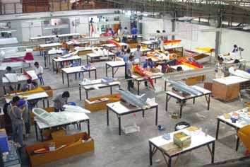
Composite-ARF Extra 330L (2 x 2m) techsupport@composite-arf.com
The ‘Paint Job’
Occasionally customers see certain problem areas with
composite parts. But the question is: Are these real prob-
lems, or are they just a misunderstood sign of high-tech
construction, proving high-end composite technology?
Seams:
ALL composite parts have seams. They are there today,
and they will be there forever. You will have to get used
to them ... or you’ll have to touch up the paint yourself !
But what is a seam? A seam on the fuselage, especially
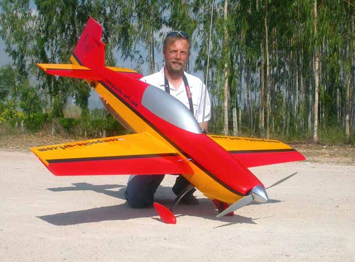
already painted in the mould, proves that this is a vacu- (above) One of our 2.6m Extra’s, in
um-bagged high-tech part, made in negative moulds. the popular ‘Fantasy red/yellow’ paint
Our seams are fine and straight, no negative impression scheme ... all painted in the moulds.
at all ... but they are there. When possible we include (below) A customer with a 3m Extra
5mm wide strips of self-adhesive vinyl, painted in exact- 330S practising his tail-in hovering !
ly the same colour as the plane for you to cover the
seams if you want.
Paint flaws:
If a plane is painted in the moulds, you can save a lot of
weight. At least 2 lbs ... and that is worth saving !
A ‘negative’ paint job is very complicated to make. The
painter cannot see the design growing and developing -
he is painting ‘blind’. He even cannot see little mistakes
and flaws, and even if he COULD, he could not correct
them. The maximum time to apply a designer paint
scheme in the mould is no more than 20 minutes. It is a big rush, because even if it is just few
minutes too slow then the masking cannot be removed without pulling off the paint itself ! This is
a BIG challenge, but the result is extraordinarily impressive. Even with slight flaws the general
appearance of these one-of-a-kind paint jobs is unique. In a ‘positive’ paint job some effects can
never be done. Just think about the shadows, peel backs, highlights, and 3D effects - and all with
a perfectly flat and uniform surface for optimum airflow and aerodynamics.
Truly hard to do, but still possible, are the paint jobs which seem so simple at first glance:
Schemes with straight lines and stripes. Quite easy with positive painting, but it’s very hard
masking the lines in the negative moulds, because we cannot assemble the parts before mask-
ing. To get the stripes lining up exactly at the rudder, wing and cowling joints is therefore almost
impossible. This is why we suggest using thin vinyl trim to make sure that these stripes line up
perfectly. Sometimes it is necessary to do that, and it is definitely not a quality problem or a
"flaw". It comes back to what is possible, and what is impossible.
If you want to have a really perfect paint job, then you might decide to have a single colour ver-
sion and have it painted by yourself or your friend.
But don’t forget: Consider the additional cost, consider the additional weight, consider that even
if it is painted ‘positive’ there will be areas you won’t be happy with. Of course you won’t com-
plain, because you created these flaws yourself… !
6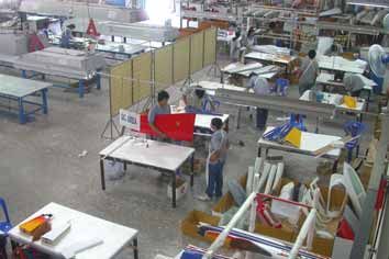
Composite-ARF Extra 330L (2 x 2m)                               techsupport@composite-arf.com

                           Tools and Adhesives
Tools etc:
This is a very quick and easy plane to build, not requiring special techniques or equipment, but
even the building of Composite-ARF aircraft requires some suitable tools. You will probably have
all these tools in your workshop anyway, but if not, they are available in all good hobby shops,
or hardware stores like "Home Depot" or similar.

1.    Sharp knife (X-Acto or similar)
2.    Allen key set (metric) 2.5mm, 3mm, 4mm & 5mm.
3.    Sharp scissors
4.    Pliers (various types)
5.    Wrenches (metric)
6.    Slotted and Phillips screwdrivers (various sizes)
7.    M3 tapping tool (metric)
8.    Drills of various sizes
9.    Dremel tool (or Proxxon, or similar) with cutting discs, sanding tools and mills.
10.   Sandpaper (various grits), or Permagrit sanding tools (high quality).
11.   Carpet, bubble wrap or soft cloth to cover your work bench (most important !)
12.   Car wax polish (clear)
13.   Paper and clear tape
14.   Denaturised alcohol, or similar (for cleaning joints before gluing)

Adhesives:
Not all types of glues are suited to working with composite parts. Here is a selection of what we
normally use, and what we can truly recommend. Please don’t use inferior quality glues - you will
end up with an inferior quality plane, that is not so strong or safe.

1.    CA-Glue ‘Thin’ and ‘Thick’ types. We recommend ZAP, as this is a very high quality.
2.    5 minute-epoxy (highest quality seems to be Z-Poxy)
3.    30 minute epoxy (stressed joints must be glued with 30 min and NOT 5 min epoxy).
4.    Epoxy laminating resin (12 - 24 hr cure) with hardener.
5.    Milled glass fibre, for adding to slow epoxy for strong joints.
6.    Microballoons, for adding to slow epoxy for lightweight filling.

At Composite-ARF we try our best to offer you a high quality kit, with outstanding value-for-
money, and as complete as possible. However, if you feel that some additional or different
hardware should be included, please feel free to let us know. Email us: feedback@composite-
arf.com. We know that even good things can be made better !

                                                7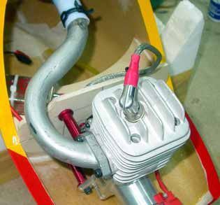
Composite-ARF Extra 330L (2 x 2m)                              techsupport@composite-arf.com

                                    Accessories
This is a list of the things you may need to get your Composite-ARF Extra 330L 2 x 2m in the
air. Some of them are mandatory, some of them can be chosen by you. What we list here are
highly recommended parts, and have been thoroughly tested.

1.    Power servos (min. 5 ). We recommend JR 8411’s for the ailerons, elevators & rudder.
2.    Throttle servo for gas/methanol motor. Any standard servo will do (eg: JR/Graupner 4041)
3.    Aluminium Spinner 82 - 86 mm dia (3.25 - 3.5”), eg: Tru-Turn.
4.    Main wheels 65 - 70mm (2.5 - 3"). Kavan Light or Dubro wheels are recommended.
5.    Engine DA-50, or electric Hacker 50 or Plettenberg Xtra 25-13. These are recommended
      engines for your Extra 330L. The instructions refer to these engines several times, but you
      could use any other 35 - 50cc gas engine, like a Zenoah 38 or ZDZ 40 - or a big 4 stroke
      (eg: OS140/160, YS140/16).
6.    Exhaust system, muffler or minipipes if using gas or methanol engine. C-ARF can supply
      headers and mini-pipes for the DA-50 as an option.
7.    Speed Controller and Flight Batteries if using Electric power
8.    High quality servo extension cables, with gold connectors. High quality
      receiver and ignition switches, ‘Y’ leads, ceramic/ferrite chokes etc.
9.    Receiver battery. Either one or two 1200 -1800 mAH NiCad packs.
10.   Fuel tank (500 - 700 ml) with gasoline stopper for gas/methanol motor. We use Dubro.
11.   Cable ties in various lengths.
12.   Propeller, to suit motor choice.

       Did you read the hints and warnings above and the instructions carefully?
              Did you understand everything in this manual completely?
      Then, and only then, let’s start assembling your Composite-ARF Extra 330L.
                If not, please read again before you start the assembly.

                          About the 2 x 2 Extra
The new Composite-ARF Extra 2 x 2m is not quite so ‘ARF’ as our other ‘planes, as there are
so many possible different building options - especially for the motor choice - and a special
option pack is available for Electric power.

However, as usual, we have included a full set of CNC milled wood parts and all the hardware
required for the completion of all the Landing gear, Flying surfaces and control surfaces. Also
included are a generic motor firewall (6mm plywood), with support former, exhaust mounting
bulkhead, Fuel tank support, rudder servo plate and throttle servo mount, which can be used
for installation of your motor choice, and/or modified as necessary. This instruction manual
shows the typical installation of a DA-50 using these parts.

This still allows us the offer a fully-composite moulded aerobatic 2m span plane, painted in the
moulds, with such a high pedigree for a truly incredible price. As technology advances and
customer requirements change Composite-ARF will continue to design and manufacture new
aircraft and follow our customers wishes and the latest trends.

We hope you will enjoy your 2 x 2m Extra and look forward to feedback on the different power
units used in this unique aircraft.

                                               8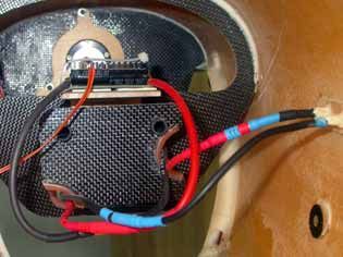
Composite-ARF Extra 330L (2 x 2m)                                techsupport@composite-arf.com

                            Building Instructions
General Tips:
We recommend that you follow the order of construction shown in this manual for the fuselage,
as it makes access to everything easier and saves time in the end.

The first thing to do is protect the finished paint on the outside of the model from scratches and
dents during building - so cover your work table with a piece of soft carpet, cloth or bubble-plas-
tic. The best way to stop small spots of glue getting stuck to the outside painted surfaces is to
give the whole model 2 good coats of clear car wax first, but of course you must be sure to
remove this 100% properly before adding any paint, decals or trim. Alternatively you can cover
the majority of the fuselage with the bubble-plastic used to pack your model for shipping, fixed
with paper masking tape, which also protects it very well.

When sanding areas inside of the fuselage to prepare the surface for gluing something onto it,
do NOT sand right through the layer of glasscloth on the inside foam sandwich! It is only neces-
sary to rough up the surface, with 60/80 grit, and wipe off any dust with alcohol (or similar) before
gluing to make a perfect joint. It is very important to prepare the inside of the fuselage properly,
by roughing up and cleaning the surface, before gluing any parts to it.

Before starting construction it is a good idea to check inside the fuselage for any loose glass
fibres that could cut your hands, and a quick scuff over any of these with a coarse Scotchbrite
pad will remove them.

Note: The photos in these instruction show the 2nd ‘Pre-Production’ prototype and some
parts in the ‘Production’ kit might vary slightly in shape or material.

Landing Gear
The 1st job is to fit the landing gear legs and you
can leave these in place to protect the bottom of the
fuselage during the rest of the assembly.

Composite-ARF developed a new carbonfibre land-
ing gear for our Extras. It consists of 45° laminated
carbon cloth and a huge number of carbon tows
inside, all made under vacuum and heat-cured.
However it is still light weight, and is flexible
enough to take the shock of any landings that are
less-than-perfect!

The plywood supports for the landing gear are
already installed at the factory, and reinforced with
fibreglass cloth. Both main legs are identical and
can be used either side. Fit the landing gear in
place on the fuselage as shown, and drill through 4
holes Ø 4mm for M4 bolts and washers. Remove
the carbon legs and open up the holes in the fuse-
lage and ply supports to 5.5mmØ. Fit the 4 blind
nuts inside the fuselage and fix with 30 min epoxy.

                                                 9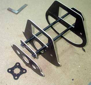
Composite-ARF Extra 330L (2 x 2m)                                 techsupport@composite-arf.com

Drill 4mm Ø thru’ the moulded mark in the bottom
of the carbon legs, and the mark in the inside of the
wheelpant for the M4 x 45mm axle bolt. Drill
6.5mmØ at the mark on the outside of the wheel-
pants, opposite the axle hole, to insert the bolt.

Glue a small milled plywood part (20mm x 10mm)
inside the inner surface of each wheel pant, about
6mm above the 4mm Ø hole for the axle bolt. (see
drawing). This part is for the sheetmetal screw that
holds the wheelpant at the correct angle to the car-
bon leg. (see photo)

Insert the wheels of your choice (65 - 70mm Ø) in
the wheelpant. The head of the bolt goes on the
outside of the wheel, inside the wheel pant. The
order of the items on the bolt is: Bolthead, washer,
wheel hub, washer, washers or wheel collars to
centre the wheel in the wheelpant, M4 nut, washer,
fibreglass wheelpant, carbon landing gear leg, and
finally another washer and the M4 locking nut. A
drop of Loctite on the bolt before tightening the
locknut is good insurance.

To set the correct angle of the wheelpants in rela-
tion to the ground, set the fuselage on a level sur-
face with your choice of tailwheel in place. Eye
through both wheelpants so that they are about
level, and secure with a 2.9Ø x13mm sheetmetal
screw in each, as shown, into the plywood plate in
side the wheel pant.

At the moment C-ARF do not supply an optional
tailwheel assembly for the 2 x 2 Extra, but any
25mm/1” Ø lightweight wheel assembly from a
hobby store will do. You do not need to
make the tailwheel steerable, a simple
                                                                         Carbonfibre landing
castoring action is fine. A milled 3mm ply-                              gear leg
wood plate (15mm x 60mm) is supplied in                                                 65 -70mm
                                                                                        Ø wheel
the kit for you to glue in the bottom of the
fuselage in front of the fin post to secure  milled ply
                                             20 x 10mm                                 wheelpant
the tailwheel assembly to.
                                                        M4 nut
Remember - keep it lightweight at the tail              washer
end!

                                                                                       M4 bolthead
                                              M4 locknut
                                                 washer                                washer

                                               washers/wheel collars
                                                             WHEELPANT X-Section

                                                10
Composite-ARF Extra 330L (2 x 2m) techsupport@composite-arf.com
Canopy
A painted moulded fibreglass
canopy is provided in the kit,
and at this time a clear cock-
pit is not available. Fitting is
simple, and with care the
canopy fit can be perfect.
Sand any seams on the fuse-
lage and canopy that prevent
it sitting perfectly flush. Mill and file the slot on the fuselage cen-
treline for the handle of hatch catch. The slot should be 2.5mm
wide x 15mm long, and the front of the slot is about 18mm behind
the edge of the fuselage moulding.
Fit the hatch catch into the white moulded plas-
tic part. You might need to drill out the hole in the
plastic part a little for a good fit. Chamfer the
front and top edges of the plastic moulding to
match the fuselage shape. Drill a 3mm Ø hole in
the fuselage flange for the pin of the catch. Apply
a little light oil or grease to the mechanism of the
hatch catch to prevent it being glued together,
and use thin CA to glue it into the plastic mould-
ing, then glue the whole assembly inside the
fuselage with 1 or 2 drops of thick CA. When the
canopy is finished this must be secured proper-
ly with some epoxy/microballoon mix. Mark the
hole on the back lip of the canopy and drill 3mm.
Fit the canopy to the fuselage and check the fit.
Sand under the front lip of the fuselage, and
then use a drop of thick CA to glue in the 3mm
milled plywood part in centrally as shown, with
the front edge of the slot in line with the fibre-
glass fuselage edge.
Glue the phenolic hook into the other milled ply
part (with the curved edge to the front), as
shown, with one drop of thin CA. The top of the
hook should be almost flush with the surface of
the plywood. Test fit in the ply part in the fuse-
lage. Now carefully wax the mating surfaces of
the fuselage and canopy in case you should get
some glue on there during the next step.
Sand the inside of the front of the canopy where
the hook plate will be glued in preparation. Slide
the hook plate into position on the fuselage part
and then apply a little 5 min epoxy to the edges
of the hook plate. Quickly slide the canopy into
11Composite-ARF Extra 330L (2 x 2m) techsupport@composite-arf.com
place, and tape in position until the glue has
cured.
Remove, check the fit, and reinforce all the joints
properly with some 30 minute epoxy and micro-
balloon mixture. Finally you can glue the pheno-
lic ‘U’ shaped plate under the slot in the fuselage
ply plate and use this to adjust the final canopy
fit. Filing the slot at a slight angle to match the
phenolic hook gives the final fine adjustment.
To make sure that the sides of the canopy match
perfectly with the fuselage shape you can add a
couple of small phenolic tongues, as shown, and
file matching slots in the fuselage lip. We have
included a spare strip of phenolic plate (15mm x
50mm) for this purpose.
Note: If you fit a gas or glow engine with higher
vibration levels, we advise you to also fit 2 ply-
wood tongues with blind nuts and M3 bolts to
retain the canopy, in a similar manner as the
cowling fixing system shown below.
Cowling
Attaching the 1 piece cowling is quite easy, as it
is already cut and trimmed at the factory, but be
careful not to deform the fuselage in this area
later when fitting the bulkheads for your choice
of motor/power unit. No bulkheads should be a
tight fit in the fuselage, sand as needed to make
them a gentle sliding fit.
Sand any seams on the fuselage and cowling
that might prevent it sitting perfectly flush. Now
carefully wax all around the mating surfaces of the fuselage
and cowling in case you should get some glue on there during
the next steps.
The cowl is secured to the fuselage with four M3 bolts and blind
nuts, fitted into 3mm milled plywood plates which are glued into
the fuselage. Additionally you should add 2 small phenolic
tongues at the back lower corners of the fuselage lip to main-
tain alignment, and prevent any rubbing or damage due to
vibration.
Mark the positions of the 4 plywood tongues on masking tape on the cowling lip, and mill and file
the slots to take the plywood parts that have a milled hole in them. The outside edges of these
slots should be about 5mm from the outside edge of the cowling lip. Make the slots 5mm wide
to easily accept the thickness of the plywood tongues with the blind nuts glued on.
12Composite-ARF Extra 330L (2 x 2m) techsupport@composite-arf.com
Sand a matching chamfer on the 4 milled ply-
wood squares (20 x 20mm), and glue them into
the cowling sides below the slots, with the inner
face as vertical as possible. Tack in place with a
drop of CA, and secure properly later with 30
minute epoxy/microballoons mix to fill any gaps
between the ply squares and the fibreglass.
When glue has cured drill a 3mm Ø hole through
the centre of these 4 ply squares and the fuse-
lage sides. Using M3 x 16mm bolts from the out-
side, fit the 4 milled ply parts with the holes in,
with blind nuts on the inner faces. Check that the
ply tongues are vertical, and adjust as needed.
Remove the ply tongues, and tape the cowling in
position on the fuselage. Transfer the positions
of the 4 tongues onto the fuselage and mill or file
the slots in the fuselage lip for the tongues.
Make the slots a fairly tight fit on the tongues.
Check that you waxed all the mating surfaces,
sand the 4 gluing areas inside the fuselage care-
fully, and apply a drop of thick 30 minute epoxy
and microballoons mix in each position, under
the slots. Bolt the 4 tongues into position on the
cowling again, and tape it into position, checking
alignment carefully, and then turn the fuselage
over quickly so it is the correct way up. After the
glue has cured you can remove the cowl, and fill
any gaps between the tongues and the fuselage
sides with a thick epoxy/micro-balloon mix.
Cut and glue in 2 small phenolic tongues in the
back lower lips of the fuselage with CA, and file
matching slots in the cowling flange for alignment. These
tongues only need to project from the fibreglass lip about 4 - 5
mm, otherwise you cannot get the cowling on and off easily.
When satisfied with the cowling fit, counterbore the 4 holes in
the cowling so that the heads of the M3 bolts sit
almost flush with the surface, and they bear on
the plywood plates that you glued in - not the
surface of the fibreglass.
13Composite-ARF Extra 330L (2 x 2m) techsupport@composite-arf.com
Horizontal Stabs
The stabs are 95% finished at the factory and
are elastic-hinged during manufacture, so you
only need to install the servos, horns and link-
ages. The fibreglass tube inside the fuselage
that accepts the stab spar is also installed at the
factory in a jig.
Insert the 14mm Ø carbon spar in the fuselage
sleeve, and install both stabs with the 50mm
long 6mm Ø fibreglass rod anti-rotation pins at
the front. Check the fit between the root ribs and
fuselage, and if you need to sand the root of the
stabs slightly to make a perfect joint use the
same method shown in the ‘Wing’ section of
these instructions. The carbon tube may need to
be shortened a little to 275mm long.
The positions of the holes in the fuselage for the
anti-rotation pins are made in the mould and
give 0° stab incidence. Drill them out 6mmØ and
glue the small plywood/carbon reinforcing rings
to the inside of the fuselage with a little 30 min.
epoxy and microballoons mix. Then fit the anti-
rotation pins into the holes in the stab roots, wax
the ends that will go into the fuse and ply rings,
and glue them into the ribs securely with epoxy.
Servo choice: The elevators can travel more
than 45 degrees, and if you are going to use the
maximum throw for 3D manoeuvres, we defi-
nitely recommend hi-torque digital servos like
JR8411. It is not just that the torque of a stan-
dard servo is not enough - it is the play in the gears which
could cause problems centering, and high speed flutter
might be the result.
The elevator servos are installed in the fuselage, due to the
thin stab profile. Put some masking tape on the fuselage, as
shown, and cut the 2 holes to size for your servos. If using
a standard sized servo, like the JR/Graupner 8411, then the
back of the servo cutouts should be 152mm (6”) from the
back of the fuselage, and the bottom edge 10 - 12mm above
the lower chine (angled corner) of the fuselage. Use the
3mm milled plywood reinforcing plates to mark the holes accurately and file to shape with a
Permagrit file or similar. Rough up the inside of the fuselage carefully, and glue the ply plates in
place with 30 min epoxy and micro-balloons mixture.
NB: Screw the servos into place with the 2.9Ø x 13mm screws provided in the kit - not the stan-
dard screws that come with the servos.
14Composite-ARF Extra 330L (2 x 2m) techsupport@composite-arf.com
The slots are already milled in the elevators for
the horns. It is important that the horns are both
in identical positions in relation to the hinge axis
- which is on the top surface of the stab - to be
sure that you have equal elevator movements.
Put a layer of tape over the area of the milled
slot, wax it, and then cut through the tape with a
sharp knife to allow the horns to be glued into
the slots. This stops excess glue getting on the
surface of the elevator. Adjust the slot in one ele-
vator so that the holes for the clevise are exact-
ly perpendicular the hinge axis, rough up the
gluing surface of the horn, and glue it in with
30min. epoxy and microballoons.
When the glue has cured on the first horn,
remove the tape, and make a horn alignment
template from thin plywood (see photo in wing
section) and a 1.6mm drill or piece of wire, and
use it to install the horn in the other elevator.
This ensures identical elevator throws.
Make up the extension leads for the 2 elevator
servos, with ceramic chokes/ferrite rings on the
servo ends, and centre both servos with your R/C. Rough up
the outer surface of two 25mmØ plastic servo output discs
with a Permagrit or 60 grit, and do the same on the inner
surface of two of the phenolic C-ARF servo arms supplied.
Tack glue the phenolic arms to the plastic discs, making
sure that they are both exactly at 90° to the bottom surface
of the stabs. Remove both and secure with 2 of the small
sheetmetal 2.2Ø x 10mm screws supplied.
Make up the elevator linkages from the 60mm long M3
threaded rods, with 2 clevises and 2 x M3 nuts for each stab. ‘Loctite’ the quick-link and lock-nut
on one end of each linkage. Add a couple of short lengths of silicone tube over the clevises to
prevent them opening accidentally. Do NOT use ball-links on the servo arms or the control-sur-
face horns, because they will twist the servo arm/horn and cause flutter. This is a solid experi-
ence and you should consider it a FACT.
Next fit the M3 stab retaining bolts. Inside the stabs you will see a small plywood reinforcement
plate between the spar sleeve and the bottom surface of the stab. Mark the bottom of both stabs
in the centre of this plywood. Install the carbon tube into 1 stab, and drill a 2.4mm hole right
through the stab surface, the plywood plate, sleeve and into the carbon tube. The centre of the
hole should be about 26mm from the trailing edge of the stab. Thread the hole with an M3 tap
and secure with an M3 x 16 bolt. Then glue an M3 blind nut inside the stab spar tube, with a lit-
tle 5 minute epoxy and micro-balloons, but be careful of adding weight here. Wax the bolt first!
Fit both stabs tightly to the fuselage, and then drill the hole in the other stab and spar tube, thread
and secure as before. Counterbore the holes in the bottom surface of the stabs for the boltheads
so that they fit flush (see cowling section). Put a piece of clear tape over the bolt heads for flight.
15Composite-ARF Extra 330L (2 x 2m) techsupport@composite-arf.com
Note: Try to always leave the stab tube fixed in
one stab, and never remove that one bolt, as it
is difficult to find the right position for the stab
tube again if it is removed from both stabs!
Rudder
The rudder is hinged to the fin with a 2mmØ
wire which passes thru’ 3 phenolic plate hinge
posts that you glue into the CNC milled balsa fin
post supplied in the kit. After hinging, the com-
plete assembly is glued into the back of the fin.
Important: You must complete the Stabiliser
section and glue the tailwheel support plate into
the fuselage before doing the rudder section,
because access is very difficult afterwards!
Trial fit the double-sided phenolic rudder horn in
the slot that is already milled in the base of the
rudder, and mark the part that will be glued in.
Remove it, mask the exposed parts and scuff
the centre part on both sides with coarse sand-
paper. Glue in place with slow (not 5 minute!)
epoxy and microballoons mix, making sure that
it is centred in the rudder. The front edge of the
phenolic horn should be flush against the back
of the balsa false leading-edge.
Prepare the 3 phenolic hinge posts by sanding
both surfaces where they will be glued into the
10mm thick balsa fin post. The balsa false-lead-
ing edge has a 2mm hole milled thru’ it ready for
the hinge wire. Open up the milled slots for the
3 hinge posts as needed. File a point on one end
of the wire, and a small 90° bend on the other
end and push it through the rudder from the top,
capturing the 3 phenolic hinges on the way.
Trial fit the balsa fin post in the back of the fin,
and fit the rudder with 3 - 5mm gap between LE
of rudder and the fin post. Check alignment and
free movement for at least 50° both ways, and
then glue the phenolic hinges into the fin post
with thin CA. A little epoxy/micro mix on the front
face of the fin post where the hinges stick thru’
ensures that they cannot come loose. Trial fit
into fin, and make sure there is 1mm gap
between top of fin and bottom of rudder mass-
balance. Sand the seams smooth if needed.
Rough sand and prepare the inside surfaces of
16Composite-ARF Extra 330L (2 x 2m) techsupport@composite-arf.com
the back of the fin and glue the fin post in with
slow epoxy and micro-balloons mix. Tape rudder
in position with a 1mm spacer on top (see
photo), and clamp fin to fin post until cured.
Servo: The rudder is a huge surface on the
Extra which definitely needs a hi-torque power
servo, and we highly recommend the digital
JR/Graupner 8411 for this important surface.
The servo is mounted in a CNC milled compos-
ite balsa plate, with the milled 3mm plywood
reinforcement underneath, in the fuselage under
the canopy area. Glue the ply plate to the bottom
of the balsa with CA and mount the servo with
the 2.9Ø x 13mm screws provided, not the stan-
dard ones that come with the servo. The com-
posite balsa rails are glued into the milled slots
under the front and back of the plate with CA.
Rough up the fuselage sides before gluing the
complete assembly into place with 30 min. epoxy, and then rein-
force these important joints with the glassfibre tape provided in the
kit, and 24hr laminating epoxy (see photo).
Note: Fit the wings to the fuselage before gluing in the rudder
servo mounting plate - so that you can-
not accidentally deform the fuselage.
We have left the milled balsa parts for
the rudder mount a bit long, so you can
chose the position to suit your motor,
and help to set the correct C of Gravity.
If you are using a lightweight set-up,
like a glow engine (or the Plettenberg
electric motor and LiPo cells) then you should move the rudder servo mounting plate as far for-
ward as possible, so that the front of the plate at the position of the rear wing anti-rotation pins.
The top of the rudder mounting plate should be 88 - 90mm above the fuselage floor. Do not
mount it lower, or the rudder closed-loop cables may touch the elevator servos. With servo
mounted as shown, the slots (40mm x 3mm) for the cable exits need to be approx. 380mm (15”)
from the back of the fin, and approx. 65mm above the chine (angled corner) of the fuselage.
Rough sand the top surface of a standard 25mm (1”) Ø plastic output disc with 60 grit, or
Permagrit, and the bottom of the phenolic rudder servo arm. Centre the servo using your R/C
and glue the phenolic horn in place perpendicular to the servo. Then remove the assembly and
secure the phenolic arm to the disc with 3 of the 2.2Ø x 10mm sheetmetal screws supplied.
Make up the closed loop wires for the rudder from the hardware supplied, with a loop at the front
that goes over the hooks on the output arms, and a quick-link with turnbuckle and locknut at the
rudder end. For security pass the closed loop cable through the supplied ‘crimping tubes’ 3 times
before squashing flat with large pliers (see photo). Make sure that the wires are tight, and check
and adjust after the first few flights as the cables straighten out. Even a small amount of slop will
prevent your Extra from perfect tracking.
17Composite-ARF Extra 330L (2 x 2m) techsupport@composite-arf.com
Wings
The wings are 95% finished at the factory, and
have already been installed on your fuselage to
check alignment. They fit on a 30mm Ø alumini-
um alloy spar tube, with 6mm Ø glass rod anti-
rotation pins at the front and back.
Each wing is secured to the fuselage with an M6
plastic bolt (glued into the wing root) and a
large plastic nut. The fibreglass spar sleeve and
carbon-ply reinforcing plates have also been
installed in the fuselage at the factory, and the
positions of the holes for the anti-rotation pins is
set in the mould to ensure correct alignment.
Drill 6mmØ thru’ the 4 positions for the anti-rota-
tion pins and also for 2 wing retaining bolts.
Slide the wings on, temporarily insert the four
50mm lengths of 6mm glass rod, and check for
a perfect fit between the root and fuselage. You
can sand the edges of the wing roots a little if
needed by protecting the fuselage with masking
tape and using 240 grit sandpaper (see photo)
Wax the outside surface of the fuselage around
the wing root area, and sand the fuselage inside
where the anti-rotation pins will stick thru’.
Lightly sand the around the heads of the two M6
plastic bolts and insert them into the holes in the
root ribs so that the threaded part projects as
shown. Do not glue in place yet.
Rough up about 25mm of end of each of the 6mmØ glass
anti-rotation rods and glue them into the holes in the wing
roots with a thick 30 min epoxy/micro-balloon mix. At the
same time apply a little epoxy mix around the heads of the
plastic bolts to secure. Quickly push the wings into position
on the spar tube, making sure that the glass rods project
inside the fuselage about 10 - 12mm, and tighten the plas-
tic nuts on the plastic bolts. It’s helpful to have a 2nd per-
son to help with this. After about an hour you can remove
the wings. Check the glue joints around the 6mmØ anti-
rotation pins carefully - these are important glue joints !
Wax the exposed anti-rotation pins and re-fit the wings. Glue the 4 milled plywood washers (car-
bon shown in these photos) onto the inside of the fuselage to retain each pin, using a
epoxy/micro-balloons mix.
Cut two small sub-ribs from 3mm scrap balsa and glue in the wing on the inner side of each
servo cutout to stiffen the wing here using epoxy/microballoon mix (see photos). Glue the phe-
nolic aileron horns into the milled slots in the same way as the elevator horns, making sure that
the clevise holes are perpendicular to the hinge axis. As before, we advise you to fit one horn
18Composite-ARF Extra 330L (2 x 2m) techsupport@composite-arf.com
first, then make a template to ensure that the other
horn is positioned the same.
Servo choice: We highly recommend using a hi-
torque digital servo (eg: JR/Graupner 8411) for each
aileron as the surfaces are quite large.
The servo hatches are pre-cut in the wing, and sup-
plied with matching servo covers and CNC milled ply-
wood servo mounts. Sand the inside surface of the
servo hatch covers and the milled plywood parts that
make up the servo mounts to make sure you have a
good gluing surface.
Assemble the servo mounts from the milled plywood
parts for each servo, using thin CA and a 90° square.
Fix the servos into the mounts with the 2.9Ø x13mm
screws supplied in the kit, and place them on the
hatch covers to check that the servo arms are in the
centre of the slots milled in the hatch covers, and
aligned with the aileron horns. Allow for the extra thick-
ness of the C-ARF servo horns that will be fixed onto
the standard plastic servo arms. You may need to
make the slots in the servo hatch covers a little wider,
by 1mm or so.
Tack glue the servo mounts to the hatch covers with
CA, then remove the servos and reinforce the glue
joints between the servo mount and the servo
cover plate with slow (min. 30 minute) epoxy
and milled fibre, with a nice glue fillet all around
(see photo). These are important joints!
Centre the servos using your R/C and fit the C-
ARF phenolic servo arms to the plastic output
discs using the same method as for the elevator
servos. Secure with 2 screws each, as for the
elevators. Fix the covers to the wing with 4
sheet-metal screws 2.9Ø x10mm provided.
Finally make up the linkages from the M3 x
60mm threaded rods supplied, with 2 clevises
and 2 x M3 locknuts for each linkage. Don’t for-
get to ‘Loctite’ the clevise and lock-nut on one
end of each linkage, and fit short lengths of tube
to prevent clevises from opening accidentally.
Do NOT use ball-links if you use these C-ARF
servo arms, because they will twist the servo
arm and cause flutter. This is a solid experience
and you should consider it a FACT.
19Composite-ARF Extra 330L (2 x 2m) techsupport@composite-arf.com
Motor Installation
The new Composite-ARF 2 x 2m design allows so many
different choices of power unit that it’s impossible to pro-
vide mounting bulkheads & hardware for all of them!
Therefore, depending on your choice of gas/methanol,
engine you need to modify the ‘generic’ milled plywood
parts we have included, or even make a few of your own.
The original prototype was flown with a DA-50, probably
the top end of the power range that anyone could possi-
ble want ... and it had lots of vertical performance! There DA-50 installed
are many other gas engines that would be suitable, for
example the Zenoah 38 or ZDZ 40, and ready-to-fly
weight with these will be in the range of 7kg (15.5 LBS)
You could also use a powerful 2 or 4-stroke glow engine, like the OS140/160 or YS140/160 -
which will give excellent, and quiet, flight performance and very light weight.
Note: No engine mounting hardware is included in the kit, because of the many different set-ups
and engine choices.
We have also done extensive flight testing with Electric power, as this is becoming a very popu-
lar choice in many countries now due to stricter noise regulations ... and we can tell you that the
performance of our 2 x 2 Xtra with Electric power is absolutely stunning. We already have a spe-
cial ‘Electric option’ pack available, which will be an extremely common option and this can be
used for the Hacker 50 or Plettenberg 25-13, or modified for other similar units. Ready to fly
weight with these units, using LiPo flight batteries, is just under 6kg (13.2 Lbs). See end of this
section for details.
DA-50 (gas engine installation)
Installation of gas or methanol engines will vary
considerably, depending on your motor choice,
but here we show a typical set-up of the DA-50
and mini-pipe.
Supplied in the standard kit are a pair of 3mm
plywood CNC milled bulkheads which have to
be glued together with epoxy to make a 6mm
thick firewall. These fit at the back of the cowl-
ing cutout (as shown), but the shape can be
modified to fit in the correct position for your
motor. Also supplied are a 3mm support bulk-
head, which is glued horizontally behind the
firewall, and a ‘blank’ 3mm plywood exhaust
bulkhead for fitting vertically immediately in
front of the Landing gear mount. These can be
modified and shaped as needed to make a
support for your mini-pipe or exhaust muffler if needed.
NB: The dimensions and positions below assume you are fitting a DA-50 engine.
20Composite-ARF Extra 330L (2 x 2m) techsupport@composite-arf.com
The main firewall should be installed at approx.
3° sidethrust, but perpendicular to the cowling
flanges (which are at 0° incidence). If using the
standard DA stand-offs (65mm/2.5” long) you
can set the approx. sidethrust for the DA-50 with
the front face of the firewall (pilots left side) is
151mm from the front of the fuselage lip, and the
right side is 157mm. Fine tuning of the sidethrust
and upthrust is set by using an incidence meter
and adding washers between the plywood fire-
wall and the stand-offs.
4 small holes have been milled in the firewall to
give you a reference point for setting the correct
position of your engine. Mark accurate lines
between these holes to use for setting your
engine position. The photo shows where the
6mm Ø holes must be drill for mounting the DA-
50, to give the correct sidethrust, and still have
the spinner central with the radiused top of the
fuselage. The dimensions shown on the firewall
in this photo suit the DA-50 and 3.5” spinner,
with 3.5° sidethrust and 0.75° upthrust - adjust
for spinner diameter of your choice.
The stand-offs should be mounted to the firewall
with M6 bolts and large diameter washers. Fit
the spinner backplate to the motor to set final
position, so that the outside edge of the spinner
is exactly in the middle of the radiused curve on
the top of the fuselage.
You will need to make a cut-out in the bottom of
the cowl as the DA-50 cylinder head sticks out a
little, but this gives excellent cooling and no
internal baffles are needed in the cowling.
With the DA-50 and a carbon 23 x 8 Mejzlik prop
we needed 3.5° right thrust and almost 1°
upthrust for correct tracking, but this will vary a
little depending on your motor/prop combination.
A TD75K mini-pipe and header from MTW is
shown fitted, and these are available as an
option from Composite-ARF, with the DA-50.
This set-up gives the engine a nice throttle
response, a perfect mid-range, and also increas-
es top end power slightly.
You can see from the photos here how to cut out
the exhaust support bulkhead for a MTW
TD75K mini-pipe, and make a steel strap and
spring to retain the mini-pipe to the bulkhead
with a little flexibility. It just fits with about 5mm
21Composite-ARF Extra 330L (2 x 2m) techsupport@composite-arf.com
clearance above to the wing spar tube, and
4mm below to the landing gear fixing bolts/blind
nuts. An alternative is the MTW TD75 mini-pipe
which is smaller diameter and gives more clear-
ance, but is a bit longer. If you chose this then
the cooling exit hole for the pipe will be further
back in the fuselage. You may need to bend the
header a little to suit whichever mini-pipe you
chose. This simple pipe retaining system has
been used for many years in all our planes, and
holds the pipes securely, while still being flexible
enough to prevent them breaking under normal
vibrations.
The air exit hole in the bottom of the fuselage
should be at about 65mm wide and 110mm long
for both pipes. Round the corners to reduce any
chance of tearing in the composite skin.
The header, and both the TD75K and TD75
mini-pipes are available from C-ARF as options.
Note: Please call your Composite-ARF Rep. if
you need any additional help with the motor
and mini-pipe installation.
Fuel Tank Base
Included in the kit are CNC milled balsa/com-
posite parts to make up a fuel-tank base, which
also incorporates a receiver mount. The photos
show how the parts are assembled, and the
completed unit is then glued on top of the fibre-
glass wing spar tube in the centre of the fuse-
lage with epoxy and micro-balloons mix.
Reinforce the joint where the vertical balsa sup-
port is glued to the fuselage bottom with a short
piece of 1” glassfibre tape and laminating resin.
The tank base is designed for fitting a Dubro 24
oz tank/700 ml (Part#424) and this is more than
big enough even for a DA-50.
If you wish to mount your receiver on the vertical
support at the back of the tank base, then glue
the milled 3mm plywood stick to the inside sur-
face, centred on the 2 large holes, wrap the
receiver in thick foam and and fix it in place with
2 No.#80 rubber bands.
The fuel tank is held to the tank base with 3
cable-ties (see photo on page 23). Drill a hole in
22Composite-ARF Extra 330L (2 x 2m) techsupport@composite-arf.com
the motor firewall where necessary for the fuel
feed tube from the tank to the carburettor, and
protect it where it passes through the hole using
a rubber grommet or similar. Fix the tubing
securely to the underside of the top of the fuse-
lage to make sure that it cannot come in contact
with the hot exhaust.
Fit the correct stopper to the fuel tank for the fuel
type used. (If using Dubro tank the gasoline
stopper has a small ‘O’ moulded in the top of it).
We use the excellent ‘Tygon’ brand of fuel tubing
for all our models. It is totally gasoline and
kerosene-proof, and does not go hard and crack
with age.
Secure the feed tube inside the tank to the clunk with a
small cable tie. If the tube is even a little loose on the brass
tubes though the stopper it will come off at just the wrong
moment and your engine will quit. So solder some small
rings onto both ends of the brass tubing (easily made from
the soft wire of a paperclip wrapped around a small screw-
driver) and secure with a fuel-line clamp or cable-tie. Don’t
miss this small detail - it could cost you your plane !
We use the normal 3-tube plumbing system, one from the
clunk to feed the motor, one out of the bottom of the plane
(vent/overflow - leave open) and one at the top for filling
(close for flight).
Throttle servo
Included in the kit is a CNC milled plywood throttle servo Throttle servo mount
mount, and you can fit this in any suitable position for your
motor set-up. However, we advise you not to mount it
directly on the back of the firewall as engine vibrations can
damage a servo quite quickly. Rather mount it on the fuse-
lage side near the wing spar tube and use a lightweight
‘snake’ (cable inside a plastic tube) to connect to the carbu-
rettor linkage, securing the outer plastic tube at several
points.
Motor ignition system
The ignition unit can be secured onto the firewall support
plate with 3 cable-ties, on a foam rubber pad to protect from vibrations. At C-ARF we recommend
a 4-cell 1000 - 1200 NiCad for ignition, and we use a Powerswitch for the ignition cut-off. Add a
very small cable tie around the plug/socket connectors from the motor pick-up to the ignition unit
for extra security.
23Composite-ARF Extra 330L (2 x 2m) techsupport@composite-arf.com
Glow Engine Installation
If fitting a 2-stroke or 4-stroke glow/methanol engine,
for example OS140/160 or YS140/160) you can gen-
erally use the same techniques as shown above for
the DA-50 (gas engine) set-up.
These will give a very lightweight aircraft, but for sure
you will need to install all components, including the
receiver battery, as far forward as possible to achieve
the correct Centre of Gravity. The Rudder servo
mounting plate should also be installed as far for-
ward as possible, and you can save some weight in
the tail by using hi-torque digital mini servos for the
elevators, of at least 5kg torque each.
Of course you will need to reposition the firewall to
suit either a solid F3A type ‘beam’ engine mount, or a
‘Hyde’ mount, as necessary. The fuel tank base,
made from the milled composite-balsa parts included, can be used and will accept a fuel tank
up to720ml if required. You can also install the receiver on the vertical bulkhead at the back of
the tank base, as for the gas engine (see photo)
The exhaust system, or mini-pipe, can still be installed internally - but make sure that there is
sufficient cooling as described, and make a balsa baffle inside the cowling if needed to direct
cooling air over the cylinder fins and prevent it just going out of the bottom air exit. If you
chose to fit a full-length tuned pipe you can make a tunnel from thin balsa sheet if you wish.
24Composite-ARF Extra 330L (2 x 2m) techsupport@composite-arf.com
Electric Power * If you are fitting a gas or glow motor, skip to page 31
Our ‘Electric Power’ Option pack includes all the main bulkheads and battery support parts
required to install either the Plettenberg Xtra 25-13 motor, or the Hacker 50 geared unit, both
powered by LiPo batteries. Considerable flight testing and demonstrations have been carried out
with the Hacker, which is the most powerful of these 2 units, and we can highly recommend this
combination.
The ‘Electric Option’ pack includes bulkheads and parts to install both
Plettenberg Xtra 25-13 or Hacker C50 geared units.
Hacker 50 (Geared 6.7:1)
A Hacker 50, fitted with an APC E22 x12 pro-
peller and LiPo cells (as shown here) is the per-
fect match for this plane. ‘Prop hanging’ needs
only about 40% throttle, and the plane will accel-
erate straight up from that with ease. Flight
times are an easy 8 or 9 minutes, depending on
your schedule. The Speed Controller used is
Hacker’s own Master 0-90-Acro unit, which per-
forms very well and gives nice throttle response.
The batteries used were a pair of ‘Thunder
Power’ 6000 mAH Lipo's, connected in series,
which give about 9+ minutes duration. The com-
plete motor/battery/speed controller combina-
tion weighs just under 2kg.
We did not use a BEC unit with this set-up, preferring a separate Rx battery (1400 mAH 5-cell),
which was needed to achieve the correct Centre of Gravity anyway.
The speed controller was fixed on a ply plate above the LiPo's, behind the motor and secured
with double-sided foam tape and a cable-tie. Make sure there is enough cooling airflow over the
heatsink.
The photos show how the 3 bulkheads are installed. The front of the motor is mounted to the
25You can also read