Connected Vehicle Pilot Deployment Program Phase 2 - Comprehensive Installation Plan - Tampa (THEA)
←
→
Page content transcription
If your browser does not render page correctly, please read the page content below
Connected Vehicle Pilot Deployment
Program Phase 2
Comprehensive Installation Plan – Tampa
(THEA)
www.its.dot.gov/index.htm
Final Report — May 2018
Publication Number: FHWA-JPO-17- 463

1.1.1.1.1.1
Produced by Tampa Hillsborough Expressway Authority (THEA)
U.S. Department of Transportation
Intelligent Transportation Systems (ITS) Joint Program Office

                                   Notice
  This document is disseminated under the sponsorship of the Department of
  Transportation in the interest of information exchange. The United States
  Government assumes no liability for its contents or use thereof.
  The U.S. Government is not endorsing any manufacturers, products, or
  services cited herein and any trade name that may appear in the work has been
  included only because it is essential to the contents of the work.

                                                                    U.S. Department of Transportation
                                               Intelligent Transportation System Joint Program Office

           CV Pilot Deployment Program Phase 2, Comprehensive Installation Plan– Tampa (THEA) i         |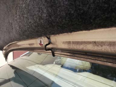
Technical Report Documentation Page
1. Report No.                                2. Government Accession No.                                   3. Recipient’s Catalog No.
FHWA-JPO-17-463
4. Title and Subtitle                                                                                      5. Report Date
Connected Vehicle Pilot Deployment Program, Comprehensive Installation Plan – Tampa (THEA)                 May 2018
                                                                                                           6. Performing Organization Code

7. Author(s)                                                                                               8. Performing Organization Report No.
Tampa Hillsborough Expressway Authority

9. Performing Organization Name And Address                                                                10. Work Unit No. (TRAIS)
TAMPA HILLSBOROUGH EXPRESSWAY AUTHORITY
1104 E Twiggs St #300, Tampa, FL 33602
                                                                                                           11. Contract or Grant No.
                                                                                                           DTFH6116H00025

12. Sponsoring Agency Name and Address                                                                     13. Type of Report and Period Covered
ITS-Joint Program Office                                                                                   Draft Report
1200 New Jersey Avenue, S.E.,
Washington, DC 20590                                                                                       14. Sponsoring Agency Code
                                                                                                           HOIT-1

15. Supplementary Notes
Work performed for:
Sarah Tarpgaard (AO), Govind Vadakpat (AOR), Kate Hartman (CV Pilots Program Manager, ITS JPO)

16. Abstract

The Tampa Hillsborough Expressway Authority (THEA) Connected Vehicle (CV) Pilot Deployment Program is intended
to develop a suite of applications that utilize vehicle to infrastructure (V2I) and vehicle to vehicle (V2V) communication
technology to reduce traffic congestion, improve safety, and decrease emissions using the authority provided by the
United States Department of Transportation within the signed cooperative agreement (DTFH6116H00025). These CV
applications support a flexible range of services from advisories, roadside alerts, transit mobility enhancements and
pedestrian safety. The Pilot will be conducted in three Phases. Phase 2 includes the design, development, and testing
phase.

This document presents the Comprehensive Installation Plan (CIP) which includes the Comprehensive Acquisition
Plan (CAP) as Appendix A.

It provides a description of the THEA Team’s approach to manage the technical specification, purchasing, installation
and provisioning of equipment, devices, software and services comprising the connected vehicle system developed
under Phase 1 and designed under Phase 2 of the THEA CV Pilot Deployment Program. The plan incorporates
activities by multiple Pilot team members and vendors.
17. Key Words                                                             18. Distribution Statement
Connected Vehicle Technology, Purchasing, CAP, CIP, ORT, On Board
Unit, OBU, Road Side Unit, RSU, Management Center, Applications,
V2V, V2I, V2X, Installation, Supplier,

19. Security Classif. (of this report)                  20. Security Classif. (of this page)                       21. No. of Pages       22. Price
Unclassified                                            Unclassified                                                       82

                                                                Form DOT F 1700.7 (8-72)                     Reproduction of completed page authorized

                                                                                                                  U.S. Department of Transportation
                                                                                             Intelligent Transportation System Joint Program Office

                                             CV Pilot Deployment Program Phase 2, Comprehensive Installation Plan– Tampa (THEA) ii                    |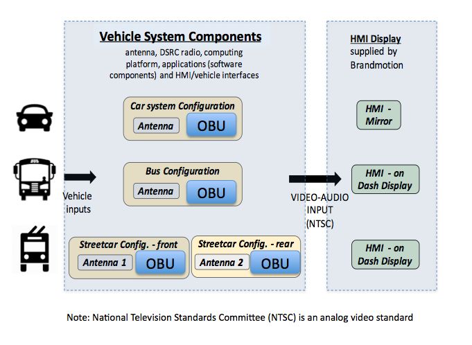
Contents
1   Introduction ................................................................................................................... 1
                PURPOSE OF THE PLAN ......................................................................................................... 1
                ORGANIZATION OF THE PLAN ................................................................................................. 1
2   Acquisition Overview ................................................................................................... 2
                INFRASTRUCTURE ACQUISITION APPROACH .......................................................................... 2
                VEHICLE SYSTEM ACQUISITION APPROACH ........................................................................... 2
                PERSONAL SYSTEM ACQUISITION APPROACH ....................................................................... 3
                INFRASTRUCTURE ACQUISITION SCHEDULE........................................................................... 3
                VENDOR OUTREACH PLAN ACQUISITION SCHEDULE ............................................................. 3
                INFRASTRUCTURE VENDOR OUTREACH PLAN ....................................................................... 3
                VEHICLE SYSTEMS VENDOR OUTREACH PLAN ...................................................................... 4
3   Installation Overview .................................................................................................... 6
                INFRASTRUCTURE SUPPLIER BASE........................................................................................ 6
                VEHICLE SYSTEM SUPPLIER BASE ........................................................................................ 6
                INFRASTRUCTURE PROCUREMENT METHOD.......................................................................... 6
                VEHICLE SYSTEMS PROCUREMENT METHOD ........................................................................ 7
                THEA SYSTEM INVENTORY MANAGEMENT............................................................................ 7
                THEA SYSTEM CONFIGURATION MANAGEMENT ................................................................... 8
                HIGH-LEVEL EQUIPMENT INVENTORY FOR INFRASTRUCTURE ................................................ 8
                HIGH-LEVEL EQUIPMENT INVENTORY FOR VEHICLE SYSTEMS ............................................... 8
                INFRASTRUCTURE INSTALLATION SCHEDULE ......................................................................... 9
                     VEHICLE SYSTEM INSTALLATION SCHEDULE .................................................................. 9
                     INFRASTRUCTURE PLAN ..............................................................................................10
                     INSTALLATION PLAN ..................................................................................................... 11
4   Vehicle / In-Vehicle Equipment .................................................................................. 13
                VEHICLE/IN-VEHICLE ITEM OBU ACQUISITION INFORMATION...............................................13
                                 Technical Description/Specification ................................................ 13
                                 Ancillary Equipment ........................................................................ 13
                                 Part Numbers and Quantities ......................................................... 13
                                 Associated Software....................................................................... 13
                                 Acquisition Method ......................................................................... 13
                                 Potential Vendors ........................................................................... 13
                                 Acquisition Schedule ...................................................................... 14
                VEHICLE SYSTEM INSTALLATION INFORMATION ....................................................................15
                                 Supplier(s) ...................................................................................... 15
                                 Inventory Control Method ............................................................... 15
                                 Configuration(s) .............................................................................. 16
                                 Installation Diagrams ...................................................................... 16
                                 Installation Procedures ................................................................... 18
                                 Quality Assurance/Quality Control Process ................................... 24
                                 Installation Schedule ...................................................................... 25
                                 HW and SW Configuration Control Process .................................. 25
                                 Sparing Strategy, Warranty and Contingency Plan ....................... 25
                                                                                          U.S. Department of Transportation
                                                                     Intelligent Transportation System Joint Program Office

                  CV Pilot Deployment Program Phase 2, Comprehensive Installation Plan– Tampa (THEA) iii                                  |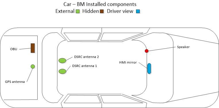
5   Infrastructure/Roadside Equipment ......................................................................... 27
               ROADSIDE EQUIPMENT RSU ACQUISITION INFORMATION....................................................27
                               Technical Description/Specification ................................................ 27
                               Ancillary Equipment ........................................................................ 27
                               Part Numbers and Quantities ......................................................... 27
                               Associated Software....................................................................... 28
                               Acquisition Method ......................................................................... 28
                               Potential Vendors ........................................................................... 28
                               Acquisition Schedule ...................................................................... 28
               INSTALLATION INFORMATION ................................................................................................28
                               Supplier(s) ...................................................................................... 28
                               Inventory Control Method ............................................................... 28
                               Configuration(s) .............................................................................. 29
                               Installation Diagram(s).................................................................... 29
                               Installation Schedule ...................................................................... 31
                               HW and SW Configuration Control Process .................................. 31
                               Sparing Strategy, Warranty and Contingency Plan ....................... 31
6   Management Center Equipment................................................................................ 32
               MASTER SEVER ACQUISITION INFORMATION .......................................................................32
                               Technical Description/Specification ................................................ 32
                               Ancillary Equipment ........................................................................ 32
                               Part Numbers and Quantities ......................................................... 32
                               Associated Software....................................................................... 32
                               Acquisition Method ......................................................................... 32
                               Potential Vendors ........................................................................... 32
                               Acquisition Schedule ...................................................................... 32
               MASTER SERVER INSTALLATION INFORMATION ....................................................................33
                               Supplier(s) ...................................................................................... 33
                               Inventory Control Method ............................................................... 33
                               Configuration(s) .............................................................................. 33
                               Installation Diagram(s).................................................................... 33
                               Installation Procedures ................................................................... 33
                               Quality Assurance/Quality Control Process ................................... 33
                               Installation Schedule ...................................................................... 33
                               HW and SW Configuration Control Process .................................. 34
                               Sparing Strategy, Warranty and Contingency Plan ....................... 34
7   Other Equipment ......................................................................................................... 35
               PEDESTRIAN DETECTION .....................................................................................................35
                               Technical Description/Specification ................................................ 35
                               Ancillary Equipment ........................................................................ 35
                               Part Numbers and Quantities ......................................................... 35
                               Associated Software ....................................................................... 35
                               Acquisition Method ......................................................................... 36

                                                                                        U.S. Department of Transportation
                                                                   Intelligent Transportation System Joint Program Office

                  CV Pilot Deployment Program Phase 2, Comprehensive Installation Plan– Tampa (THEA) iv                               |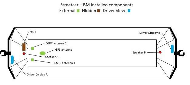
Potential Vendors ........................................................................... 36
                                    Acquisition Schedule ...................................................................... 36
                                    Installation Schedule ...................................................................... 36
8      Bill of Materials (BOM) ................................................................................................ 37
                    INFRASTRUCTURE BOM ......................................................................................................37
                    VEHICLE SYSTEMS BOM .....................................................................................................38
9   Glossary ....................................................................................................................... 42
10 References ................................................................................................................... 43
11 Acronyms ..................................................................................................................... 44
Appendix .............................................................................................................................. 45

List of Figures
Figure 1 – OBU Wiring Diagram ........................................................................................... 12
Figure 2 – Example Position of OBU Mounting .................................................................... 16
Figure 3 – In vehicle Mechanical Installation Diagram ......................................................... 17
Figure 4 – Bus Mechanical Installation Diagram .................................................................. 17
Figure 5 – Streetcar Installation Diagram.............................................................................. 18
Figure 6 – Drip Loop in Vehicle ............................................................................................. 21
Figure 7 – Drip Loop Example .............................................................................................. 21
Figure 8 – Conformance Workflow........................................................................................ 30

List of Tables
Table 1 – High-Level Infrastructure Equipment Inventory....................................................... 8
Table 2 – High-Level Vehicle System Equipment Inventory ................................................... 8
Table 3 – High-Level Infrastructure Installation Schedule....................................................... 9
Table 4 – Vehicle System Installation Schedule ................................................................... 10
Table 5 – Acquisition Schedule ............................................................................................. 14
Table 6 – Installation Schedule.............................................................................................. 25
Table 7 – RSU Part Numbers and Quantities ....................................................................... 27
Table 8 – Pedestrian Detection Part Numbers and Quantities ............................................. 35
Table 9 – Infrastructure Bill of Materials ................................................................................ 37
Table 10 – In Vehicle Systems Bill of Materials..................................................................... 38

                                                                                             U.S. Department of Transportation
                                                                        Intelligent Transportation System Joint Program Office

                       CV Pilot Deployment Program Phase 2, Comprehensive Installation Plan– Tampa (THEA) v                                |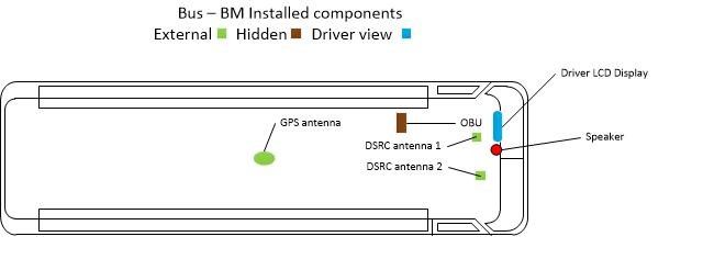
1 Introduction

The Comprehensive Installation Plan (CIP) provides information on the policies, plans and processes
to procure, manage and install the equipment, software and services to support the Tampa
Hillsborough Express Authority (THEA) Connected Vehicle (CV) Pilot Deployment. In addition to
documenting the procurement and installation plans, it will serve as a baseline management tool for
process improvement, lessons learned and financial performance. While individual partner
procurement and installation details may be sensitive, a blended reporting system is intended such
that future CV deployments may benefit from their review.

As noted in the cooperative agreement general terms and conditions (paragraph C “Data Rights”), the
Recipient need not submit annual property report using the form SF-428 – Tangible Personal Property
Report.

However, THEA CV Pilot has utilized firm fixed pricing model for its system development and
deployment, there is no equipment to be reported separately from those costs. The United States
Department of Transportation (USDOT) has agreed that these forms will not be required of THEA CV
Pilot under this set of procurement circumstances. But the THEA team will work cooperatively within
the team and vendors to provide meaningful breakouts of costs that might be used to extrapolate
future deployment budgetary insight.

      Purpose of the Plan
This document describes acquisition and installation policies and procedures for the THEA CV Pilot. It
serves as a resource to the THEA team for guidance and management of the procurement process. It
is also intended as a resource for others interested in early deployment of CV technologies. Finally, it
is intended to provide a documentation framework and validation tool for USDOT.

      Organization of the Plan
The CIP is organized into the following sections:
   • Section 1 This section provides the high-level overview of the installation
   • Section 2 Acquisition Overview
   • Section 3 Installation Overview
   • Section 4 Vehicle/In-Vehicle Equipment
   • Section 5 Infrastructure/Roadside Equipment
   • Section 6 Management Center Equipment
   • Section 7 Other Equipment
   • Section 8 Bill of Materials
   • Section 9 Glossary
   • Section 10 References
   • Section 11 Acronyms

                                                                          U.S. Department of Transportation
                                                     Intelligent Transportation System Joint Program Office

                  CV Pilot Deployment Program Phase 2, Comprehensive Installation Plan– Tampa (THEA) 1        |
2 Acquisition Overview
Infrastructure Acquisition Approach
The Siemens acquisition process is described in the Comprehensive Acquisition Plan (CAP),
Appendix A. The key components and services requiring an acquisition plan are summarized as:
• Roadside Unit (RSU) Kits that include:
o RSU
o Dedicated Short Range Communications (DSRC) antennas
o WiFi antennas
o Bluetooth antennas
o Global Positioning System (GPS) antennas
o Mounting hardware
o Cabling
o Power over Ethernet (PoE) Injectors
• Radar detection for Wrong Way detection of unequipped vehicles on outbound REL
• Radar detection for queue lengths of inbound REL
• Video detection for unequipped vehicles approaching signalized intersections.
• Traditional pedestrian detection for movements of pedestrians and cyclists
• Master Server that includes:
o Server hardware
o Data storage
o Communications equipment
The process in Section 2 of the CAP details the acquisition process used by Siemens in this project
that includes the key steps of engineering design, supplier selection, sourcing and testing, and
process improvement. Figure 1 of the CAP depicts the Infrastructure and Back Office equipment
acquisition work flow.
Vehicle System Acquisition Approach
The Brandmotion acquisition process is described in the Section 3 of the CAP, the key components
and services requiring an acquisition plan and described in this document can be summarized as:
• Human Machine Interface (HMI) components (cars, buses and streetcars)
• On-Board Units (OBUs) components (multiple suppliers)
• Wiring assembles/components (Brandmotion and supplier sourced)
• Antennas (multiple suppliers)
• Mounting hardware
• Installation Services
The process in Section 3 of the CAP details the acquisition process used by Brandmotion in this
project that includes the key steps of engineering design, supplier selection, sourcing and testing and
process improvement.
U.S. Department of Transportation
Intelligent Transportation System Joint Program Office
CV Pilot Deployment Program Phase 2, Comprehensive Installation Plan– Tampa (THEA) 2 |Personal System Acquisition Approach
The Siemens acquisition process for Personal Information Device (PID) and associated software
applications:
• Participants agree to provide their own PID in the form of a smart phone
• Siemens provides a list of eligible PID for prospective participants
• PID using the Android operating system only.
o Android is exclusively chosen as the only device supported by the MMITSS
applications being tested
o Android allows distribution of 3rd party software applications from the Master Server,
opposed to required distribution through the store
o Support of IOS devices is out of scope, but the resulting applications are available for
port to IOS by other developers
• Chosen participants receive the object code and instructions to install the app on their PID as
well as an installation key code texted separately
Infrastructure Acquisition Schedule
Section 2.2 of the CAP presents the acquisition schedule – component delivery dates and Application
Development Schedule requirements.
Vendor Outreach Plan Acquisition Schedule
Section 3.8 of the CAP presents the acquisition schedule – component delivery dates and Application
Development Schedule requirements. Note: Standard Green/Yellow/Red (GYR) risk assessment
process is used: Green means no issues, yellow mean issues with high confidence mitigation plans,
red means issue with no plans – high risk
Infrastructure Vendor Outreach Plan
As described in Section 2 of the CAP, Siemens open vendor outreach consists of the following
process that began before this project with the publication of USDOT RSU specification version 4.0
plus requirement from Europe (EU) and the United Kingdom (UK):
1. USDOT issues the RSU Requirements Specification, version 4.0 (v4.0) based on lessons
learned in the prior test beds.
2. United States of America (USA) RSU Requirements specification document based on v4.0,
plus added requirements for THEA, including WiFi for pedestrian safety, cellular backhaul to
collect data, Bluetooth reader for travel times, high-speed multiple core processor to run
multiple applications, plus added memory to collect data and to store multiple MAP files.
3. RSU management and back office requirements from USA, Europe (EU) and United
Kingdom (UK).
4. EU and UK RSU requirements
5. USA software requirements for RSU version using the DSRC WAVE communications
extracted as a separate document.
6. USA hardware requirements extracted as a separate document, based on v4.0 plus WiFi,
Bluetooth, cellular, processing speed and memory capacity.
U.S. Department of Transportation
Intelligent Transportation System Joint Program Office
CV Pilot Deployment Program Phase 2, Comprehensive Installation Plan– Tampa (THEA) 3 |7. EU and UK hardware requirements
8. EU and UK software requirements based on EU and UK wireless standards
9. Development of USA RSU software
10. Procurement document for common RSU hardware based on combined USA, EU and UK
requirements issued to RSU manufacturers for competitive bid.
11. Development of EU/UK RSU software
12. Announcement at ITSA World Congress, Bordeaux of strategic partnership among Siemens,
Cohda and NXP Live demonstration conducted using a Honda test vehicle, Cohda RSU and
OBU, Cohda OBU applications and Siemens RSU applications. These existing applications
were matched to the THEA Use Cases and Study Areas for the USDOT Pilot.
13. Cohda and NXP added to the Strategic Partnership entry of the Siemens Affiliated Test Bed
informational slide
14. THEA vendor day in Tampa Florida. Multiple RSU and OBU manufacturers demonstrated
their equipment. Based on the feature sets and verbal prices stated, decision to continue with
the RSU designed to THEA requirements manufactured by Cohda instead of starting over
with another RSU manufacturer.
15. USA RSU software completed for v4.0 plus the added THEA requirements.
16. Cohda delivers first article RSUs for integration test with the USA RSU software and EU/UK
RSU software. Integration testing is completed for each.
17. EU/UK RSU software is completed.
18. USA RSU software is updated based on integration testing with first article RSU hardware.
19. Hardware design update completed based on integration and environmental testing
20. EU/UK RSU software is updated based on integration testing with RSU hardware
21. Final USA software is integrated with first production run of RSU hardware
22. RSU hardware first production run completed. (25) units delivered to THEA project for
developers, testers, security scans and spares.
23. Final EU/UK software is integrated into first production run hardware
24. USDOT issues v4.1 RSU Requirements Specification that does not affect hardware, but
requires software update and repeat of integration testing in the USA.
25. Requirements specification issued for pedestrian detection and vehicle detection equipment.
26. RSU Back Office and RSU Management development for USA, EU and UK requirements
27. USA RSU software update and repeat of integration testing to v4.1
28. Detection equipment cost quotes received and evaluated, including Lidar, radar and video.
29. Successful field test at Southwest Research Institute. Included controller unit sending signal
countdown to RSU. RSU created SPaT, MAP and TIM messages to three OBU vendor
vehicles. Vehicles send BSM to RSU over complete 780-meter track distance.
30. Detection equipment procurement for vehicles and pedestrians.
31. RSU Management and Back Office integration test and subsystem test with RSUs
32. USDOT Pilot installations in Tampa Florida
33. Second production run of RSUs, including 40 units for field installation in Tampa Florida
34. EU and UK RSU field installations, using EU/UK RSU software
Vehicle Systems Vendor Outreach Plan
As described in Section 3 of the CAP, Brandmotion open outreach consisted of the following process:
1. Create Product Design Assumptions, completed Phase 1 by Brandmotion with THEA team
input
2. Initiate Request for Proposal as needed, completed Phase 1 by Brandmotion with THEA
team input
U.S. Department of Transportation
Intelligent Transportation System Joint Program Office
CV Pilot Deployment Program Phase 2, Comprehensive Installation Plan– Tampa (THEA) 4 |3. Required Request for Quotation to evaluate partners/suppliers, completed December 2016
by Brandmotion with THEA team input and review
4. Supplier Selection, completed January 2017 by Brandmotion with THEA team
5. Finalize Specifications, Statement of Work (SOW) with Program Timing, completed July 2017
by Brandmotion with THEA team input
6. Sourcing commitment, intent to source completed by Brandmotion with THEA team input
7. Program Purchase Orders, completion August 2017
U.S. Department of Transportation
Intelligent Transportation System Joint Program Office
CV Pilot Deployment Program Phase 2, Comprehensive Installation Plan– Tampa (THEA) 5 |3 Installation Overview
Infrastructure Supplier Base
The list of supplier base is described in Section 4 of the CAP and summarized as follows:
• RSU Supplier:
o Cohda Wireless procured to Siemens requirements specification document
• Radar Vehicle Detection Supplier Candidates:
o Wavetronics
o Siemens
o MsSedco
• Video Vehicle Detection Supplier Candidates:
o Iteris
o Econolite
o Flir
o Gridsmart
• Lidar Pedestrian Detection Supplier Candidates:
o Metrotech
o Quanergy
• Radar Pedestrian Detection Supplier Candidates
o Siemens
• Video Pedestrian Detection Supplier Candidates
o Iteris
• Master Server Supplier Candidates
o Hewlett Packard
o Dell Computer
Vehicle System Supplier Base
The list of supplier base is described in Section 3 of the CAP and summarized as follows:
• OBU Suppliers:
o Savari
o SiriusXM
o Commsignia
• Antenna Supplier:
o Harada
Infrastructure Procurement Method
The infrastructure procurement method flow is diagramed in Figure 1 of the CAP and described in
Section 2.1.1. The procurement of the RSU began with publication of the RSU Requirements
Specification version 4.0 and was awarded prior to this project. The RSU Requirements Specification
issued to candidate suppliers includes updates to version 4.1 of the specification, plus additional
features to meet the project requirements including WiFi for pedestrian safety and others.
U.S. Department of Transportation
Intelligent Transportation System Joint Program Office
CV Pilot Deployment Program Phase 2, Comprehensive Installation Plan– Tampa (THEA) 6 |Procurement of pedestrian detection equipment began with a Requirements Specification document
submitted to manufacturers of video, radar and lidar pedestrian detection products shown in
“Infrastructure Supplier Base” above. Lidar technology met the performance requirements, while
radar and video technologies could not.
Procurement of vehicle detection equipment began with a Requirements Specification document
submitted to manufacturers of video and radar vehicle detection products shown in “Infrastructure
Supplier Base” above. Radar was selected as the most cost-effective solution for the varying weather
and lighting conditions in Tampa.
Procurement of wrong-way detection equipment began with a Requirements Specification document
submitted to manufacturers of video and radar vehicle detection products shown in “Infrastructure
Supplier Base” above. The selection of radar was based on an existing and proven product already
widely deployed in Florida for other wrong-way detection needs.
Vehicle Systems Procurement Method
The vehicle systems procurement method is described in section 3 of the CAP.
THEA System Inventory Management
Inventory management for the infrastructure and back office equipment is implemented using the
Siemens SAP accounting and manufacturing software that includes:
• Material procurement
• Assignment of internal Siemens part numbers linked to vendor part numbers
• Incoming Receiving of material
• Inventory control with stocking locations
• Issuing material from stock to installers
• Return Material Authorizations (RMA) for repair and warranty material
• Inventory audits
The Inventory Management flow is as follows:
1. The RSU kit is assigned an internal Siemens part number shown in Section 4.1.3 of the CAP.
2. Internal Siemens part numbers are assigned stocking locations
3. Equipment vendors are set up as Siemens suppliers in SAP
4. Internal Siemens part numbers are linked to supplier part numbers in SAP
5. Part numbers and quantities are entered into the SAP procurement screen with delivery dates
6. Equipment is received and logged into SAP, then moved to the assigned stocking locations
7. Secured staging storage area is created at the THEA building in Tampa Florida with limited
access by Siemens installation personnel.
8. Equipment received in the stocking location in Austin Texas is delivered to the staging storage
at THEA on the installation schedule.
9. Inventory counts are adjusted in SAP as the material is shipped to the installer.
10. Installers obtain equipment from secure storage in Tampa as the installations proceed.
11. Any defective or damaged equipment is returned under RMA and replaced.
12. Inventory is audited by the Siemens commercial (accounting) staff in Austin Texas.
U.S. Department of Transportation
Intelligent Transportation System Joint Program Office
CV Pilot Deployment Program Phase 2, Comprehensive Installation Plan– Tampa (THEA) 7 |THEA System Configuration Management
The Configuration Management (CM) is part of the Work Breakdown Structure (WBS) described in
section 3.5.1.1.2 of the Comprehensive Deployment Plan (CDP) consisting of five project Quality
Gates at which CM is performed as follows:
• QG1: After investigation of all needed hardware and software objects to the Requirements
• QG2: After test and verification of each hardware and software object delivered to the project.
• QG3: After integration of software objects into hardware objects as subsystems
• QG4: After subsystems are integrated and tested with interfaces as a complete system
• QG5: After Field Testing
CM at Siemens follows the mature Siemens Product Evolution Process (PEP) that requires
configuration and work product archives using the Perforce software system for archiving and revision
control, as the Siemens Helpdesk issue tracking system with issue resolution archives
High-Level Equipment Inventory for Infrastructure
Table 1 is an inventory of the infrastructure equipment procured and installed.
Table 1 – High-Level Infrastructure Equipment Inventory
Equipment Type # Procured Total # Configured and Installed
RSU Kits 65 44
Pedestrian Detector 1 1
Vehicle Detector 1 1
Wrong Way 1 1
Detector
High-Level Equipment Inventory for Vehicle Systems
Table 2 is an inventory of vehicle equipment procured and installed.
Table 2 – High-Level Vehicle System Equipment Inventory
Equipment Type Total # Procured Total # Configured & Installed
Vehicle OBU ~1610 1580
Streetcar/Bus OBUs ~25 20
Antennas (3 per ~4850 4800
vehicle)
U.S. Department of Transportation
Intelligent Transportation System Joint Program Office
CV Pilot Deployment Program Phase 2, Comprehensive Installation Plan– Tampa (THEA) 8 |Infrastructure Installation Schedule
Table 3 is the milestone dates for infrastructure equipment installations.
Table 3 – High-Level Infrastructure Installation Schedule
Date Task Description
July 2017 Site Survey Inspection of each RSU location
Measure the conduit runs for cable
Document location of each device installation location
Create “as built” engineering drawings
Test clearance of exiting conduit to accept additional
cables
August 2017 Begin Installation Installation of 44 RSUs
Installation of 1 pedestrian detector
Installation of 1 wrong way detector
Installation of 1 vehicle detector
November 2017 Installation Completion Final acceptance test of all equipment installed
Vehicle System Installation Schedule
The installation of competed systems consists of three vehicle system types, 1580 participant
vehicles, 10 buses and 10 streetcars. Table 4 depicts the installation schedule for Hillsborough
Community College (HCC) under Brandmotion supervision.
• OBU and other component delivery
• Friends of Pilot are THEA-owned vehicles and THEA employee private vehicles equipped as
early adopters for testing ahead of the participant vehicle installation.
• Build days per week are the number of days the installers occupy the community college
service bays each week.
• Weekly Build Target total are the number of participant vehicle installations per month on
average
U.S. Department of Transportation
Intelligent Transportation System Joint Program Office
CV Pilot Deployment Program Phase 2, Comprehensive Installation Plan– Tampa (THEA) 9 |Table 4 – Vehicle System Installation Schedule
Planned Component Deliveries to HCC Installations by HCC/Brandmotion
Vehicles
installed
Mirrors, Comm- Sirius for Build
Savari Build Rate/ Weekly
Month Wiring, signia XM Partici- Buses/ Days
OBU day Build
2018 Antenna, OBU OBU pants Streetcars per
(1250) (utilization) Target
etc. (250) (100) Target week
(cumula-
tive)
Friends of
March Initial TBD - TBD -
Delivery the pilot Initial
and Delivery 1-3 establish establish
to HCC builds and Builds
prior to HCC process process
Launch
Initial Initial Initial 7-10
Delivery
April Delivery Delivery Delivery ramp up Ongoing 4.5 vehicles 36
to HCC
to HCC to HCC to HCC (33%)
Final
Delivery Periodic
May NA Delivery 400 Completion 4.5 22 (90%) 99
to HCC Delivery
to HCC
Delivery Periodic
June NA NA 800 NA 4.5 22 (90%) 99
to HCC Delivery
Delivery Periodic
July NA NA 1200 NA 4.5 22 (90%) 99
to HCC Delivery
Final Final
Delivery
August Delivery NA Delivery 1600 NA 4.5 22 (90%) 99
to HCC
to HCC to HCC
Note: The chart assumes participants are available for installation and does not account for no
shows and no builds
Infrastructure Plan
Site surveys are complete in July 2017. Site survey is conducted by a two-person crew that:
• Measures the intersection geometry and lane marking placement
• Determines the optimum RSU location by line of sight to vehicle approaches
• Locates the existing electrical conduit for routing the RSU cable
• Inspects the existing conduit by running an electrician’s tape from the electrical cabinet to the
RSU mounting pole to clear any debris and insects
• Records the controller type and software release number
• Records the communications media and adaptors
• Records the malfunction management unit type and software revision number
U.S. Department of Transportation
Intelligent Transportation System Joint Program Office
CV Pilot Deployment Program Phase 2, Comprehensive Installation Plan– Tampa (THEA) 10 |• Photographs the intersection and cabinet interior for use by the civil engineer to create “as
built” engineering drawings.
Elevation plans, electrical diagrams, hardware mounting details, communications network diagrams
are created based on the site survey to be delivered per the project schedule. Installation and
acceptance tests are completed per the project schedule.
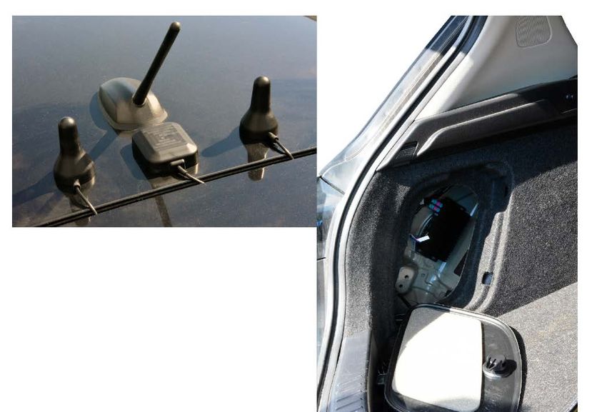
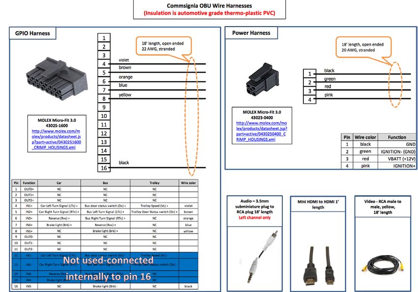
Installation Plan
We have acquired wiring diagrams from all OBU suppliers and are working with wiring harness
suppliers for procurement. Figure 1 is an example of one of the wiring diagrams. The color code
column refers to standardized color codes of the physical wire. No standardized SAE wire colors are
used in the automotive industry. RED is typically +12V and BLACK is typically 0V. Differing colors are
used to identify wires routed through the vehicle.
We have completed antenna testing for best placement and performance of antennas on vehicles.
HMI component has been tested and procurement plans were established. Installation and
acceptance test to be completed per the project schedule.
U.S. Department of Transportation
Intelligent Transportation System Joint Program Office
CV Pilot Deployment Program Phase 2, Comprehensive Installation Plan– Tampa (THEA) 11 |Figure 1 – OBU Wiring Diagram
U.S. Department of Transportation
Intelligent Transportation System Joint Program Office
CV Pilot Deployment Program Phase 2, Comprehensive Installation Plan– Tampa (THEA) 12 |4 Vehicle / In-Vehicle Equipment
The Brandmotion Acquisition Schedule, as described in Section 3.7 of the CAP, is a matrix that details the
following:
• Brandmotion part number
• Industry part number, several of the parts are COTS
• Specification and release engineer
• Contract and Purchase Order status
• Delivery and Purchase responsibility (buyer)
• Application Development Schedule requirement
Vehicle/In-Vehicle Item OBU Acquisition Information
Brandmotion as described in Section 3 of the CAP procures the Onboard Units under contract and Service Level
Agreement from Commsignia, SiriusXM and Savari.
Technical Description/Specification
Brandmotion communicates OBU technical information to the suppliers through a document, VEHICLE
SYSTEMS - OBU COMPONENT SPECIFICATION, OBU_COMPSPEC_BM_THEA v2.2 which incorporates the
requirements from the System Architecture Document (SAD) and the System Design Document (SDD).
Ancillary Equipment
As described in Section 3 of the CAP and in the Acquisition Schedule matrix and in section 4.1.7, the antennas
are purchased from Harada, wiring, video adapters and display components from Brandmotion.
Part Numbers and Quantities
The Acquisition Schedule matrix shown in Table 5 below provides the description and part numbers, quantities,
and source of all components.
Associated Software
The application software of the OBU for the THEA applications as listed in the SAD are part of the OBU
purchase. A license for use of the software for the THEA pilot is addressed in the OBU purchasing contract.
Acquisition Method
Reference Section 3 of the CAP
Potential Vendors
Reference Section 3 of the CAP
U.S. Department of Transportation
Intelligent Transportation System Joint Program Office
CV Pilot Deployment Program Phase 2, Comprehensive Installation Plan– Tampa (THEA) 13 |Acquisition Schedule
The Acquisition Schedule Matrix is detailed in Table 5 below. Note: This is a working and dynamic document that is periodically updated by Brandmotion.
Table 5 – Acquisition Schedule
Legend: Green indicates task complete
Yellow indicates task to be completed, minor issues
Red indicates task not complete and major issues need to be resolved`
U.S. Department of Transportation
Intelligent Transportation System Joint Program Office
CV Pilot Deployment Program Phase 2, Comprehensive Installation Plan– Tampa (THEA) 14 |Vehicle System Installation Information
Supplier(s)
As described in Section 3 of the CAP, Hillsborough Community College is under contract to Brandmotion to
provide installation services.
Inventory Control Method
Brandmotion shall develop and establish the Inventory Control Method (ICM). Detailed inventory of each item
ordered, received and shipped shall be recorded in the Brandmotion-THEA Standard Inventory file system.
HCC shall record via the approved Brandmotion and HCC ICM. Detailed inventory of each item ordered,
received and installed shall be recorded in the Brandmotion-HCC Inventory file system located at HCC. The ICM
will include date ordered, date received, date installed, any discrepancies or defects in parts received during
incoming inspection or installation. HCC shall maintain the ICM file electronically on a shared drive with
Brandmotion. The ICM will be updated on a daily basis by HCC. Brandmotion shall review the ICM on a regular
basis and upon any special request to review inventories.
U.S. Department of Transportation
Intelligent Transportation System Joint Program Office
CV Pilot Deployment Program Phase 2, Comprehensive Installation Plan– Tampa (THEA) 15 |Configuration(s)
There will be multiple antenna configurations exercised during installation depending on vehicle type. Below in
Figure 2 is an example of one. Also, depending on the OBU and vehicle type, the OBU could be mounted in
different locations. Below in Figure 2 is an example position of the mounted OBU.
Figure 2 – Example Position of OBU Mounting
Installation Diagrams
This section provides the detailed installation diagram(s).
4.2.4.1 In-vehicle mechanical installation diagram
Figure 3 depicts the installation locations of each hardware device in the private vehicles. Each vehicle will have
two DSRC antennas installed, one will be used solely for safety channel and one for control channel. Each car
will also have a separate GPS antenna for accurate positioning. The OBUs will be hidden and installed in the
trunk of the car and mirror with a speaker up front for the interface with the driver.
U.S. Department of Transportation
Intelligent Transportation System Joint Program Office
CV Pilot Deployment Program Phase 2, Comprehensive Installation Plan– Tampa (THEA) 16 |Figure 3 – In vehicle Mechanical Installation Diagram
4.2.4.2 Bus mechanical installation diagram
Figure 4 depicts the installation locations of each hardware device in HART buses. Each bus will also have two
DSRC antennas installed, one will be used solely for safety channel and one for control channel. Each bus will
also have a separate GPS antenna for accurate positioning. The OBUs will be hidden and installed inside a
cabinet onboard the bus and display with a speaker up front for the interface with the driver.
Figure 4 – Bus Mechanical Installation Diagram
4.2.4.3 Streetcar installation diagram
Figure 5 depicts the installation locations of each hardware device in TECO streetcars. Each streetcar will also
have two DSRC antennas installed, one will be used solely for safety channel and one for control channel. Each
streetcar will also have a separate GPS antenna for accurate positioning. The OBUs will be hidden and installed
inside a cabinet onboard the streetcar and display with a speaker up front for the interface with the driver. There
will be a second set of display and speaker installed in a the second onboard cabinert for when the streetcar
reverses the direction of travel and the driver moves to the other side.
U.S. Department of Transportation
Intelligent Transportation System Joint Program Office
CV Pilot Deployment Program Phase 2, Comprehensive Installation Plan– Tampa (THEA) 17 |Figure 5 – Streetcar Installation Diagram
Installation Procedures
The sections below illustrate the intended timing and procedural outlook for the two-hour appointment block
required for the installation of antennas, on-board units, and rear-view mirrors to the participant’s approved
vehicle. The participant will, at the time of their appointment, be trained on the usage and intended reactions
regarding the equipment and safety messages they will receive. They will also receive and sign an informed
consent document regarding their participation in this human use study.
Responsibilities and authorities:
Reception, Booking, Training Global-5 Communication
Installation, Testing HCC
Equipment, Support Brandmotion
4.2.5.1 Pre-Installation Procedures/Checklist
Reception of the Participant
The participant(s) will be greeted at the entrance of the HCC Ybor Campus Training Center by the trainer on duty
at the time of their appointment. Signage will be posted to direct participants to drive to the appropriate entrance,
where an HCC technician will receive their vehicle, instructing the driver of any needs for access that may be
affected by the interior condition of the vehicle. The technician will then drive the participant’s vehicle to the
appropriate bay, where the custom kit and supplies will be ready for installation prior to the arrival of the vehicle
based on the weekly appointment schedule provided to HCC from Global-5.
Vehicle Inspection and Preparations
HCC technicians will inspect the vehicle once in the bay to assure the proper make, model, and trim has been
reported by the participant from the application process. Technicians document if any additional features not
previously reported via the application process are present on the rear-view mirror, or within the car’s
programming, specifically if any collision avoidance system is found. The technician brings these items to the
attention of the trainer immediately. Participants at that time will be asked if they wish to continue with the CV
Pilot in the case of features not being retained by the newly installed rear-view mirror. A document regarding
feature loss is also presented and signed by the participant at that time. Collision warning systems will not be
accepted, and participants whose vehicles are found during the inspection process to have such a system will
not be allowed to continue with the CV pilot.
U.S. Department of Transportation
Intelligent Transportation System Joint Program Office
CV Pilot Deployment Program Phase 2, Comprehensive Installation Plan– Tampa (THEA) 18 |Informed Consent
Following the inspection, the participant will be shown a brief video regarding their consent as a human-use case
study during the duration of the CV pilot, in accordance with NIH regulations. An informed consent document
must be signed by the participant prior to the installation process beginning in the bay, and the training courses
being given. Once signed, the technicians may begin the installation, and the trainer may begin the coursework
with the participant. This informed consent document may be a digital document, stored via tablet. The tablet
used will be secured, and locked every night in a secure location at the HCC Ybor Campus Training Center.
Bus and Streetcar installations
For the bus and streetcar installations, HART and Global-5 will provide training to their drivers separately and the
informed consent form will be from HART, not individual bus/streetcar drivers like it is for participant vehicles.
4.2.5.1.1 OEM Vehicle Pre-Installation Procedures/Checklist
1. Verify and annotate vehicle make, model year, model version and all unique add-ons not installed by
OEM.
2. Identify Rear View Mirror features and annotate.
3. Acquire from HCC stock inventory all matching required vehicle installation components, to include:
OBU, wire harnesses, antennas, cables, brackets, antenna location decals, etc.
4. Annotate any vehicle discrepancies, windows and surface marks, and blemishes, scratches, missing
OEM equipment, burn marks, general under hood (engine) and any broken interior and exterior items.
5. Start and operate vehicle to annotate all electrical functions operate. To include:
a. Radio, rear view mirror functions, any vehicle or engine tell-tale lights, fault indicators, wipers,
door locks, windows, seats, lights, lighting etc.
4.2.5.1.2 Bus Pre-Installation Procedures/Checklist
1. Verify Bus is in good safe operating condition from HART and is an approved model year version as
agreed upon between Brandmotion and HART.
2. Check for any special equipment installed that may impair installation of Brandmotion (BM) Connected
Vehicle Pilot (CVP) equipment.
3. Acquire from HART stock inventory all matching required Bus installation components, to include: OBU,
wire harnesses, antennas, cables, brackets, and antenna location decals etc.
4. Start and operate vehicle to annotate all electrical functions operate. To include:
a. Radios, fare collection equipment, any vehicle or engine telltale lights, fault indicators, wipers,
lights, lighting etc.
b. Ensure there is adequate mounting space inside the electronic components box.
4.2.5.1.3 Streetcar Pre-Installation Procedures/Checklist
1. Work with HART Streetcar technician to ensure and verify Streetcar is in good safe operating condition
from HART.
2. Check for any special equipment installed that may impair installation of BM CVP equipment.
3. Acquire from HART stock inventory all matching required Streetcar installation components, to include:
OBU, wire harnesses, antennas, cables, brackets, antenna location decals etc.
4. Start and operate vehicle to annotate all electrical functions operate. To include:
a. Radios, fare collection equipment, any vehicle or engine tell-tale lights, fault indicators, wipers,
doors, lights, lighting etc.
b. Ensure there is adequate mounting space inside the recommended OBU location area.
U.S. Department of Transportation
Intelligent Transportation System Joint Program Office
CV Pilot Deployment Program Phase 2, Comprehensive Installation Plan– Tampa (THEA) 19 |4.2.5.2 Installation Procedures
Once informed consent is given, the installation process may begin in the bay. The technician(s) will remove the
existing rear-view mirror, placing the stock part in a container to be returned to the participant. The custom kit,
provided by Brandmotion, will then be installed, including the OBU in the trunk or under dash of the vehicle,
antenna(s) on the roof of the vehicle, wiring along the frame of the vehicle, and the rear-view mirror with video
display along the windshield or ceiling of the vehicle. Following installation, the technician(s) will test the
connection between the OBU and a stationary RSU located in the bay, or outside for clear sky reception. The
technician will make certain data is received by the RSU, and that safety messages are received by the OBU,
and transmitted to the screen in the newly installed rear-view mirror.
Once installation has begun, the participant will be trained in the use cases, warning system, and intended
reactions. A series of videos will be shown to the participant, along with visuals for each individual safety
message that will be displayed. The participant will also be informed of the control and treatment groupings, but
will not be informed as to which set they will placed in during the test phase of the pilot.
The Center for Urban Transportation Research (CUTR) has set up the initial survey online. At the installation
appointment, after the participant has signed the Informed Consent Document, the participant is asked to go
online and take the survey. Once the survey is complete, training would proceed. The Participant IDs will be
linked to the survey.
4.2.5.2.1 Vehicle CVP Equipment Installation Procedures
1. Acquire all necessary CVP equipment from HCC CVP inventory.
2. Verify which OBU system you will be installing (Commsignia, Savari or SiriusXM) and follow the
included installation instructions contained in the OBU specific install kit.
3. Vehicle ignition power is off.
4. Install OBU with mounting bracket into trunk or under dash area as necessary for vehicle type.
Nuts, bolts included in parts bag supplied. Note: In some applications Velcro may be utilized.
5. Install the video converter box to the OBU using the supplied cable.
6. Connect OBU wire harnesses to OBU. Note: All wire leads will cut to length after determining the
routing and lengths necessary. Recommend adding extra 20% or more length to allow for future
movement if required.
7. Connect all GPIO wires to locations specified in the verified OBU manufacturer Vehicle Interface
Wiring Diagram (IWD).
i. Use supplied splices, tape and connectors supplied in parts bag.
ii. Wires must be routed and secured to prevent movement and chafing. Allow extra
length to prevent any stress on wires or connectors.
8. Route the RCA video cable to the Rear-View Mirror.
9. Mount the Rear-View Mirror into the recommended location using hardware supplied in parts bag.
10. Connect the RCA cable to the Rear-View Mirror. Secure cable. Make sure it is not loose or in view
of the operator.
11. Route the audio cable to the Speaker. Be careful not to locate the audio cable next to radio
electrical radio wires to prevent electrical audio interference.
12. Mount the Speaker into the recommended location using hardware supplied in parts bag.
13. Connect the audio cable to the Speaker. Secure cable.
14. Connect all power and ground wires onto locations specified in the Vehicle IWD.
15. Locate and apply the 2 DSRC antenna location decals per the locations specified in the “Vehicle
DSRC antenna location guide.”
16. Install the two magnets mounted or adhesive mounted DSRC antennas onto the roof covering the
locating decals.
a. Route the DSRC antenna coaxes into the vehicle trunk (or other location for the OBU).
b. Create a coax “drip loop” just before or in the trunk seal gap (see Figure 6 and Figure 7).
U.S. Department of Transportation
Intelligent Transportation System Joint Program Office
CV Pilot Deployment Program Phase 2, Comprehensive Installation Plan– Tampa (THEA) 20 |You can also read