Coupler Interlocks for SRF Cavities - How to Keep Your Machine From Going Down for Weeks or Months - Indico
←
→
Page content transcription
If your browser does not render page correctly, please read the page content below
Coupler Interlocks for SRF Cavities

How to Keep Your Machine
From Going Down for Weeks
or Months.

Tom Powers
Jefferson Lab

Presented at TTC workshop
At Triumph, Feb. 2019

With input from various colleagues from other labs
CRYOMODULE INTERLOCKS
• NEVER OPERATE A CRYOMODULE WITH HIGH
  POWER RF AND THE COUPLER INTERLOCKS
  BYPASSED ! ! ! !        • RF Driven Interlocks
• Coupler Interlocks         • Quench detection
       •   Arc detector(s)                                  •   E2/PFWD ratio
       •   Coupler vacuum                                   •   Gradient Present with RF off
       •   Window temperature                               •   Gradient Error
       •   Water flow (If water cooled)                     •   Phase Error
       •   Electron probe (Useful but not required)         •   Excessive detune
       •   Water temperature (Useful but not required)
• Cryomodule
       •   Cavity vacuum
       •   Helium level
       •   Helium pressure (Useful but not required depending on cryo plant)
       •   Insulating vacuum (Useful but you only look at it after you find out that you
           can not maintain liquid level.)

TTC Triumpf, Feb. 2019, Coupler Interlocks, T. Powers   2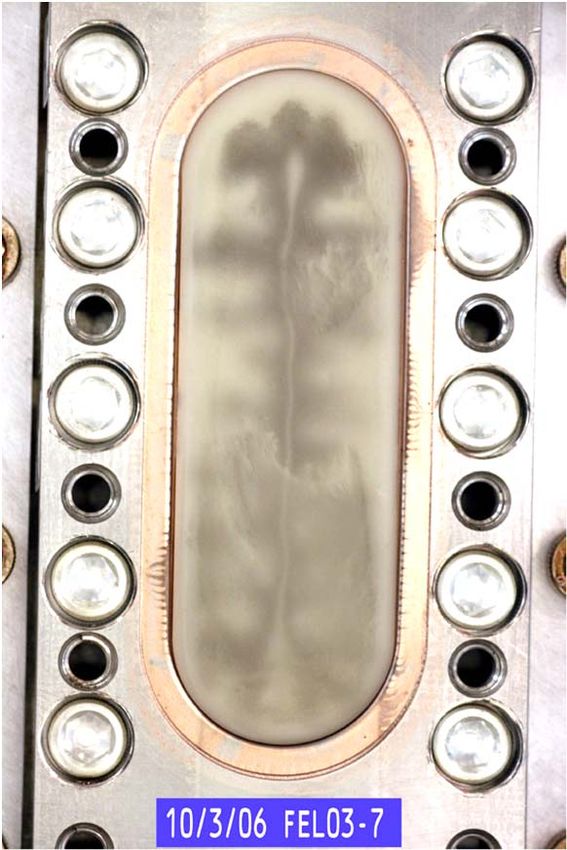
Why Do We Care About Coupler Interlocks
• A coupler failure that vents the coupler vacuum but not the beam line vacuum
  means that you will lose the ability to use that cavity for days or months and will
  shut down your machine for at least a few day. Be prepared with a plan and
  hardware for blanking off a failed coupler.
• A coupler failure that vents the beamline will probably take your machine down for
  months and you can expect to have substantially degraded performance in that
  cryomodule forever.
• My experience is that failure that involves a catastrophic beam line vacuum failure
  will degrade the usable gradient by about 50%.

   Rexolite window that was operated with no interlocks. Trapped gas due to
   horizontal placement caused failure at power much less than that used on
   test stand with vertical position.
   Ceramic window with soot imbedded in it. After checking with an IR
   camera and RF we continued to use the cryomodule for 13 Years so far.

  TTC Triumpf, Feb. 2019, Coupler Interlocks, T. Powers   3
Optical Spectra from CEBAF Waveguide Arcs*

              Alumina window CrO2 coating 800 uS gate

              Alumina window TiN2 coating 800 uS gate

                  Alumina window TiN2 coating 1 uS gate          •   This work was done with an immersed
                                                                     cavity.
                                                                 •   Data taken on a cryomodules indicated
Alumina window with elbow TiN2 coating 300 uS gate                   other gas species on a cavity with a warm
                                                                     to cold transition or arcs in warm window
                                                                     sections.
                              Kapton window 800 uS gate          •   The general theory is that arcs are
                                                                     normally induced by electrons or soft
                                                                     xrays striking the surface of the ceramic
                                                                     window.
                                                                 •   We found repeatedly that a 3 mm thick
                                                                     window will likely develop a small
                                                                     (1e‐6 Torr) leak after 50 arcs.
TTC Triumpf, Feb. 2019, Coupler Interlocks, T. Powers     4   *Powers, et. al. 1995 SRF Conference.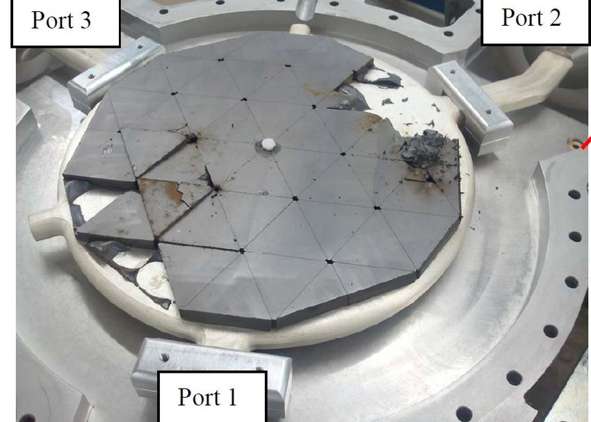
PMT Based Arc Detectors
                                 Test LED
                                                         Socket with 7V
                                                         to 1 kV DC‐DC
                                                         converter

• Photomultiplier tube based (most sensitive by orders of magnitude)
• Universally home made detector heads
• Historically JLAB used a 931B tube which is a side window tube that is now out of
  production. We have operational PMTs in CEBAF that are more than 20 years old.
• Our current choice is a Hamamatsu R7446 tube which has radiation tolerant, quartz
  window.
• I have heard that some other labs use head on tubes.
• PMTs will respond (mostly scintillation of the glass) to beam loss and must be masked
  for loss of tune-up beam, for us that means a 500 us delay before a trip.
• We use twisted pair wires with a 100 Ohm termination and an amplifier with a gain of 10
  and BW of a few MHz, there are two systems the 25 year old design uses a comparator
  and PLD logic for the gate function the newer one uses a 1 MS/s ADC and FPGA logic.
 TTC Triumpf, Feb. 2019, Coupler Interlocks, T. Powers      5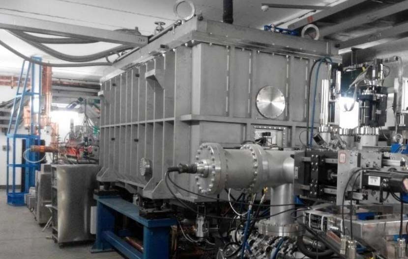
Arc Detectors
• Photo Diode Based.
     - Typically the AFT Microwave arc detectors with a fiber optic between the coupler optical
       port and the electronics.
     - Their manual indicates a 2 us to 7 us response time.
     - There have been issues with rad hardness (e.g. darkening) of the fibers glass fiber
       bundles. They carry a plastic 2 mm fiber that that has more attenuation which is, to quote
       the manual, “known for its superior radiation hardness”.

                                                            AFT Arc Detector 4 System
• Test LED
     - Each of our detector heads has a built in test LED.
     - We test our arc detectors once per hour cycling through the zone.
     - We have had problems with radiation damage of the LEDs.
     - Somehow you have to verify that your system is operational. For machines that are only
       turned on occasionally one could consider just disconnecting the fiber and pointing it at
       the light.
TTC Triumpf, Feb. 2019, Coupler Interlocks, T. Powers   6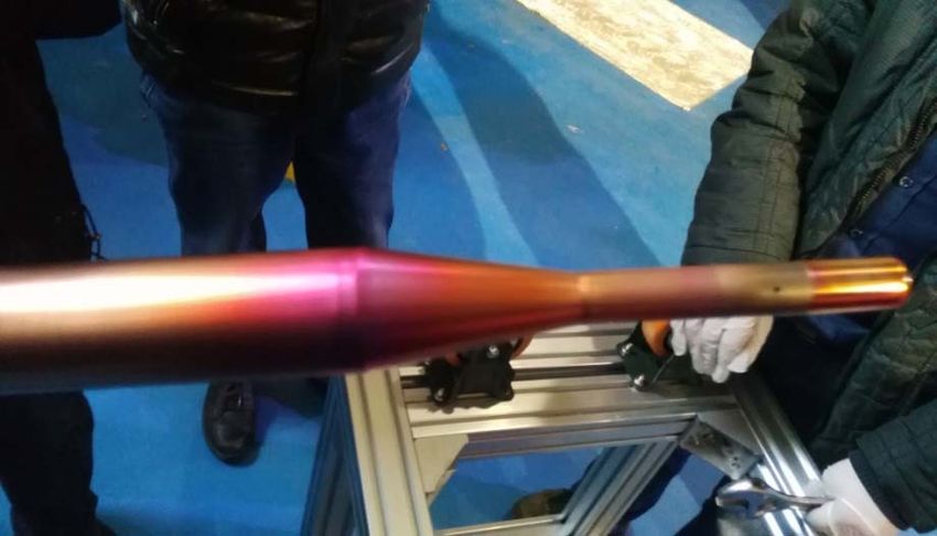
RF Signals for Two Different Arc Types

• Vacuum discharge in the vacuum space between two coupler windows.
      - The discharge acts more like a matched load and the gradient decays away at
        a time constant consistent with the loaded Q-of the system.
      - In CEBAF C50/C20 cavities which have a window at 2K these are triggered by
        electronic quenches.
      - In CEBAF C100 cavities, which have two warm windows, the inner window
        vacuum space gets conditioned and electronic quenches do not trigger
        waveguide vacuum arcs.

• Vacuum discharge on the cavity side of the coupler window known as an
  Electronic Quench.
      - In these events a burst of gas gets into the high field region of the cavity.
      - The electrons are stripped off of the gas atoms
      - The electrons accelerated by the cavity fields sucking all of the energy out of
        the cavity very quickly, typically 10 us but as fast as 100 ns.
      - These events are accompanied by a very large X-ray burst which occurs when
        the cloud of electrons strike the metal surfaces.

TTC Triumpf, Feb. 2019, Coupler Interlocks, T. Powers   7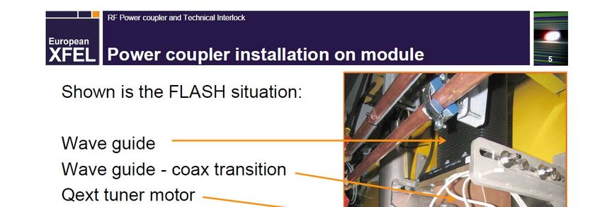
Typical Waveguide Vacuum Arc

•   Arc starts at ‐500 us and the control loop responds by turning up the RF drive to the maximum.
•   At 0 the RF is turned off and the discharge is sustained by the emitted power due to the stored
    energy in the cavity which is decaying at more‐or‐less a time constant determined by the Loaded‐Q.
•   If beam were to remain on it would also sustain the discharge by sustaining the cavity fields.

    TTC Triumpf, Feb. 2019, Coupler Interlocks, T. Powers   8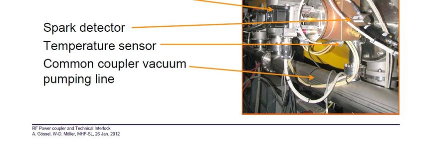
Typical Electronic Quench (Arc on cavity side of window)

•   Arc starts at ‐500 us and the control loop responds by turning up the RF drive to the maximum.
•   Even with RF power at the maximum, the cavity field collapses in about 50 us due to the free
    electrons from the discharge inside the cavity.
•   During the 500 us that the electronics waits before turning off the RF, the excess power creates an
    arc in the waveguide vacuum space. Note: We do not see the secondary arcs in the C100
    cryomodules which have two warm windows.
•   At 0 the RF is turned off and the discharge in the waveguide is extinguished.
    TTC Triumpf, Feb. 2019, Coupler Interlocks, T. Powers   9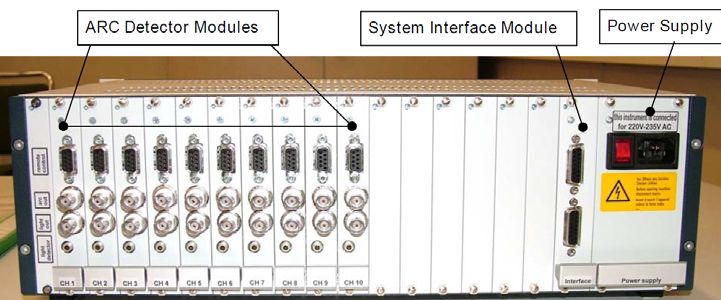
Coupler Vacuum Interlock
                                                         • Typically the interlock on ion pump
                                                           controller, cold cathode gauge or hot
                                                           cathode gauge is used as an interlock.

                                                         • For a system with two warm windows the
                                                           recovery time from a discharge in the
                                                           coupler vacuum space is tens of seconds.

                                                         • For a system with a cold surface in the
                                                           vacuum space the time constant is much
                                                           faster due to cryo-pumping.
                                                             - CEBAF C50/C20 Cryomodules have a 30 ms
                                                               vacuum recovery time even though the pump
                                                               takes a few seconds to recover.
                                                             - The waveguide gets pumped out quickly and it
                                                               is the pump itself that you are waiting on which
                                                               is isolated from the cold surface by a 0.5 m
                                                               long pipe.
                                                             - Systems with cold cathode gauges typically
                                                               use a stainless tube that is about 0.5 cm in
                                                               diameter which are even slower to pump out to
                                                               the cold surface.
                                                             - Typical set-points are 10-6 to a few 10-5 Torr
TTC Triumpf, Feb. 2019, Coupler Interlocks, T. Powers   10
Window Temperature
• There are two issues with ceramic or composite windows.
• Overall or peak temperature to damage threshold.
• Non-uniform heating OR COOLING causing mechanical stress.
• At Jefferson Lab we use non-contact thermopile sensors from Dexter Research,
Model M34.
- Thermopiles provide a temperature difference between the sensor and a sensor that is
heated by the IR light, (and visible if there is no window).
- A thermopile is a series of thin film temperature coated with an IR absorbing coating (the
hot sensors) and a series sensors of which are thermally isolated from the hot sensors.
- For applications in air we use the ones with germanium windows.
- You can purchase them without windows for vacuum applications.
• Other labs use RTDs or thermocouples for monitoring the coupler temperatures.
• While RTDs mounted on flanges can help in diagnosing overall temperature rise,
thermopiles can be effective in detecting hot spots due to braze or localized
material defects.
• JLAB instituted a 100% quality assurance testing program on the windows using
an off line 16 kW RF test stand. All windows are monitored with a FLIR camera for
rate of temperature rise, peak temperature, temperature distribution and thermal
hot-spots with RF applied in full reflection where the window is tested in at he peak
of the standing wave.
TTC Triumpf, Feb. 2019, Coupler Interlocks, T. Powers 11Images of thermopile detectors
• The sensor shown in the photo is the one we use in the vacuum space
• In the C50/C20 cryomodules and for the vacuum side C100 sensor it
responds to reflected light (14 um to visible) on the surface of the
copper plated waveguide which has an 85% reflection coefficient in the
7 to 14 um wave legnths.
• For the air side C100 sensor it has germanium window and a line of site
to the waveguide window.
• We solder the sensors onto a multiconductor vacuum feedthrough
along with a 100 Ohm resistor which is used as a test source during the
interlock verification process.
• You must calibrate your IR sensor with experimental data.
TTC Triumpf, Feb. 2019, Coupler Interlocks, T. Powers 12Thermal Images of Normal and Abnormal RF Windows.
• Window after operation at 12 kW
for 2‐3/4 hours.
• Window passed with uniform
temperature distribution across
the window.
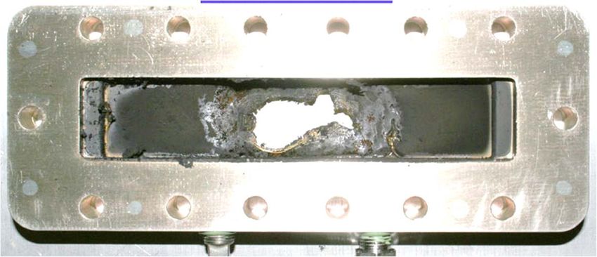
• Window after operation at 11 kW
for 2‐1/2 hours.
• Test aborted due to uneven heating
indicating a bad braze on left hand
end of window.
• Would be difficult to identify with
thermal sensors on the frame.
TTC Triumpf, Feb. 2019, Coupler Interlocks, T. Powers 13Other Interlocks
• Water flow for water cooled couplers, water inlet and outlet temperature
are useful but not always necessary.
• Air flow for air cooled windows
• Electron probes are in place, but typically only used only for conditioning.
• Coupler vacuum
- Is typically done with a commercial vacuum gauge controller.
- Is used for conditioning couplers especially important when conditioning
warm to cold transition.
• RF signals can effectively be used as coupler interlocks.
-Rapid loss of gradient, less than tens of microseconds, indicates an
arc on the cavity side of the coupler.
-Loss of gradient at slower rates and a substantial increase in RF
power can be an indicator of an arc in the inter window vacuum
space.
TTC Triumpf, Feb. 2019, Coupler Interlocks, T. Powers 14Bypassing arc detector interlocks is a bad idea.
Unmitigated arcing can cause direct damage to insulators and metal surfaces. Additionally,
they can lead to metal plating of insulators and eventual failure due to heating.
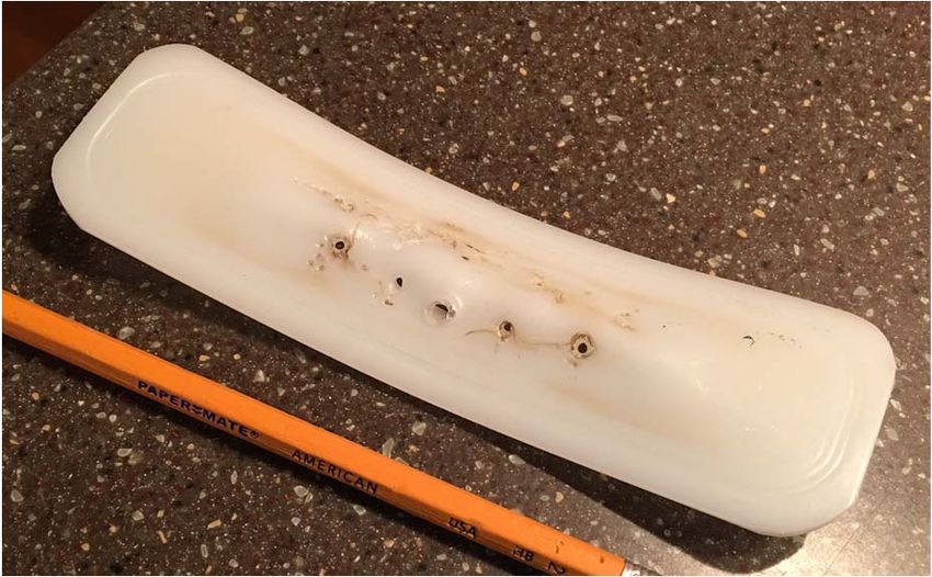
• Damage to a polyethylene window which
occurred when the interlocks were set up
in an odd state which required an operator
to re-enable them after each trip.
• By the time that folks got into the tunnel to
investigate there was liquid air pouring out
of the holes in the window.
• Damage to a one-off 20 kW CW Circulator
(6 week repair time)
• Root cause tracking source on a spectrum
analyzer connected directly to the high
power amplifier drive on a 200 MHz HPA
used for SRF gun being developed at
University of Wisconsin (Aladdin).
• This bypassed the arc detector that
normally would protect the circulator.
TTC Triumpf, Feb. 2019, Coupler Interlocks, T. Powers 15Other Lab TTC Triumpf, Feb. 2019, Coupler Interlocks, T. Powers 16
Radiation Source at ELBE*                                                                       FPC antenna tip        cavity

                                       coax waveguide                      inner conductor with
                                                                           PT100 temp. sensor     inner conductor

                    H bent with                                                                   outer conductor
                    vacuum port                                                  interface to
                                                                                 cryomodule       ceramic windows
                                                                                                  (cold window at 77K)
 IR Sensor for
Warm window

                                                                                                  PT100
                                                                             WR650 doorknob
                                                                                                  temp. sensor
                                                                             transition to coax

                                                Warm Window          PMT for cold window
air cooling for
warm window
                                                   PMT for warm window
         note: left picture taken from RIs MESA module description

 ELBE Coupler Interlock for 16kW CW at 1.3 GHz per cavity
 - 2 PMTs, 1 for cold window, 1 for each warm window (H5783 or H11901 from Hamamatsu)
 - 1 PT100 for inner conductor of the FPC, cold windows and inner conductor are cooled by LN
 - 1 IR temperture sensors (Raytech) for warm window (quartz), cooled by fan-discharge duct
 - 1 vacuum gauge (Pfeiffer IKR060) per FPC to monitor coupler vacuum

 RF is switched off whenever a certain thresholds of at least one sensor is exceed.
 PMTs are fast interlocks with time for total RF shutdown of
IMP Vacuum Event
• Running for 1 year, two coupler in TCM6 were
leaking, Vacuum interlock: 5E-4Pa
• CM1,CM2 running for 10 days, 2 couplers
were leaking because of the bypass of
vacuum interlock. Before the accident,
cavities were running well. After that, the
nearby cavities also degraded.
• Arc detector fiber had very poor transmission
and was replaced.
TTC Triumpf, Feb. 2019, Coupler Interlocks, T. Powers 18 * Provided by Tiancai Jiang, Gao ZhengSummary*
Warm Cold Arc Water
RF PWR Type Win Win Arc Det Test Temperature Vacuum Flow
JLAB C100 12 kW CW Waveguide 2 0 1 PMT Y 2 Non Contact Ion Pump None
JLAB C50 8 kW CW Waveguide 1 2K 1 PMT Y Non Contact Ion Pump None
JLAB C20 5 kW CW Waveguide 1 2K 1 PMT Y Non Contact Ion Pump None
ELBE 20 kW CW Coaxial 2 PMT ? Non Contact Cold CCG Water?
XFEL 30 kW pulsed Coaxial 1 50 K? Diode ? 300K & 70K 1 Ion pump N cav
LCSL II 3.8 kW Coaxial 1 50K None 2 @ 50J 1 Ion pump 8 cav None
Cbeta Inj 2x75 kW 2 Coaxial 1 50K PMT 2 CCG ?
Cbeta Linac 5–10 kW CW Coaxial 1 50K None ?
SNS 850 kW Pulsed Coaxial 1 2 AFT Y Non Contact 1 CCG Yes
IMP 20 kW Coaxial 1 or 2 1 AFT N 1 or 2 Hot cathode
FRIB Coaxial 1 1 Yes Cernox
• There are a variety of interlock schemes used around the world.
• It has been shown on any number of occasions over the years that bypassing them will
lead to nothing but trouble.
• It is also critical that one insure that interlocks are functioning properly on a regular
basis, after extended downs and in off normal operational modes.
TTC Triumpf, Feb. 2019, Coupler Interlocks, T. Powers 19 *Thanks to many colleagues in this roomYou can also read