CozIR-Blink Evaluation Board User Guide - Gas Sensing ...
←
→
Page content transcription
If your browser does not render page correctly, please read the page content below
CozIR®-Blink
                                  Evaluation Board
                                                  User Guide

Gas Sensing Solutions Ltd.                                               Revision 1.2, 29 March 2021

Page | 1   For regular updates, sign up at https://gassensing.co.uk   Copyright © 2021 Gas Sensing Solutions Ltd.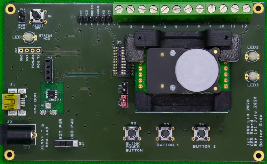
USER GUIDE

                                                               TABLE OF CONTENTS
INTRODUCTION ........................................................................................................................... 4
USB DRIVER ................................................................................................................................. 5
SOFTWARE INSTALLATION ........................................................................................................... 5
INSTALLING THE SENSOR .............................................................................................................. 5
EVALUATION BOARD CONCEPT .................................................................................................... 6
STANDALONE OPERATION............................................................................................................ 8
SENSOR POWER SUPPLY............................................................................................................... 9
   Method 1 - External Power Supply ..................................................................................................... 9
   Method 2 - USB Power Supply ............................................................................................................ 9
   Method 3 - Variable External Power Supply ..................................................................................... 10
SENSOR POWER CONSUMPTION MEASUREMENT ....................................................................... 12
ENVIRONMENTAL CONDITION MONITORING.............................................................................. 12
EVALUATION BOARD BUTTONS, JUMPERS AND LED INDICATORS ................................................ 12
SOFTWARE USER INTERFACE ...................................................................................................... 13
RUNNING THE SOFTWARE .......................................................................................................... 14
SENSOR SELECTION .................................................................................................................... 15
CO2 SENSOR MEASUREMENT...................................................................................................... 16
OTHER ENVIRONMENTAL SENSORS ............................................................................................ 18
CURRENT MEASUREMENT .......................................................................................................... 19
GRAPHING SENSOR DATA .......................................................................................................... 20
ZERO-POINT SETTING THE SENSOR ............................................................................................. 21
   ZERO IN NITROGEN ........................................................................................................................... 22
   ZERO IN AMBIENT CONDITIONS ....................................................................................................... 22
   ZERO IN A KNOWN GAS CONCENTRATION ....................................................................................... 22
PRESSURE COMPENSATION ........................................................................................................ 23
BLINK MODE SETTINGS .............................................................................................................. 24
AUTO-ZERO FUNCTION .............................................................................................................. 25
AUTO-ZERO INTERVALS .............................................................................................................. 25
   AUTO-ZERO LEVEL ............................................................................................................................. 25
SENSOR COMMUNICATIONS ...................................................................................................... 26
DATA DISPLAY ........................................................................................................................... 27
DATALOGGING........................................................................................................................... 29
TERMINAL VIEW ........................................................................................................................ 31
TERMINAL VIEW – UART READ ................................................................................................... 32

Gas Sensing Solutions Ltd.                                                                                   Revision 1.2, 29 March 2021

Page | 2   For regular updates, sign up at https://gassensing.co.uk                                       Copyright © 2021 Gas Sensing Solutions Ltd.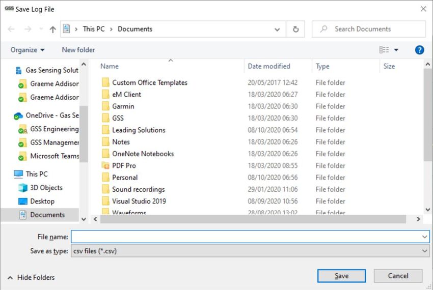
USER GUIDE

TERMINAL VIEW – UART WRITE.................................................................................................. 33
TERMINAL VIEW – I2C WRITE ...................................................................................................... 34
TERMINAL VIEW – I2C READ........................................................................................................ 35
MECHANICAL DIAGRAM ............................................................................................................. 37
IMPORTANT NOTICE .................................................................................................................. 38
ADDRESS ................................................................................................................................... 38
REVISION HISTORY ..................................................................................................................... 39

Gas Sensing Solutions Ltd.                                                                               Revision 1.2, 29 March 2021

Page | 3   For regular updates, sign up at https://gassensing.co.uk                                   Copyright © 2021 Gas Sensing Solutions Ltd.
USER GUIDE

INTRODUCTION
This evaluation board is designed to provide a fast and easy start for evaluation of the GSS CozIR®-
Blink-N sensor. The CozIR®-Blink-N sensor is designed to be power cycled and pre-programmed to
take one reading per power cycle. This means that power to the sensor must be removed and re-
applied before the sensor will take another reading. Power cycling can be done using the evaluation
board software, or manually.

The evaluation board brings several interfaces and interconnections shown in Figure 1.

The CozIR®-Blink-N Evaluation Board is designed to allow the user to evaluate all the hardware and
software functions of the sensor. This manual provides information about the board’s
interconnections, jumper settings, communications, and debug interfaces.

The sensor can be controlled by a PC application via the USB interface, or standalone and controlled
externally via connections to the sensor on the evaluation board.

The sensor and other supporting electronics can be evaluated using a PC software application. This
provides the user with a graphical user interface to all the main functions of the sensor, as well as a
terminal mode, allowing the user to write and read data directly from the sensor registers.

As well as evaluating the CO2 sensor, the software application allows the user to monitor and store
other environmental conditions such as pressure, relative humidity, and temperature.

The evaluation board also has the capability to measure the current consumption of the sensor in
any of its operating modes, allowing the use to accurately assess real world power use over time.

Alternatively, the sensor can be completely separated from all the other electronics on the
evaluation board and controlled directly by the user via edge connectors. All data, control and
status pins of the sensor can be connected to connectors, J3, J4 and J5. Power is provided via a
separate edge power connector (J2), via USB (J1), or directly via header (J5).

For more technical information on the sensor, download the appropriate data sheet from here:
https://www.gassensing.co.uk/products/

Gas Sensing Solutions Ltd.                                                    Revision 1.2, 29 March 2021

Page | 4   For regular updates, sign up at https://gassensing.co.uk        Copyright © 2021 Gas Sensing Solutions Ltd.
USER GUIDE

USB DRIVER
To interface to a PC, the evaluation board requires a USB-A to USB-Mini B cable and a USB driver to
function correctly. Recent versions of Windows will automatically identify and install the USB driver
when you plug in the lead.

If the USB driver is not installed, or the evaluation board will not connect to a COM port, please
download the USB driver from the FTDI website:

https://www.ftdichip.com/Drivers/VCP.htm

Choose “VCP Drivers” and select the correct driver for your operating system.

SOFTWARE INSTALLATION
The GSS evaluation board software is available direct from the GSS web site. Download the .zip file
to your computer. Unzip and click on Setup.exe and follow the instructions on the screen.

INSTALLING THE SENSOR
The sensor needs to be connected to the board. Rotate the fixing cams out of the way to allow
insertion of the sensor. When the sensor is correctly seated on the pin headers, rotate the cams into
place, clamping the sensor into place.

Insert the sensor before applying power to the board or connecting the USB interface. Refer to
figure 2 on the following page of this user manual to determine the correct sensor orientation.

Gas Sensing Solutions Ltd.                                                    Revision 1.2, 29 March 2021

Page | 5   For regular updates, sign up at https://gassensing.co.uk        Copyright © 2021 Gas Sensing Solutions Ltd.

USER GUIDE
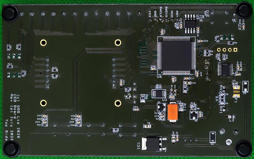
EVALUATION BOARD CONCEPT
Figure 1: Evaluation Board Key Components
The evaluation board consists of a USB interface device, which connects to an on-board
microcontroller. The on-board microcontroller connects to the sensor using either its UART
or I2C interface. The interface mode from the microcontroller to the sensor is user
selectable.
The microcontroller also interfaces to the environmental monitoring sensors. The
evaluation board comes with temperature, humidity, pressure, and current sensors.
Gas Sensing Solutions Ltd. Revision 1.2, 29 March 2021
Page | 6 For regular updates, sign up at https://gassensing.co.uk Copyright © 2021 Gas Sensing Solutions Ltd.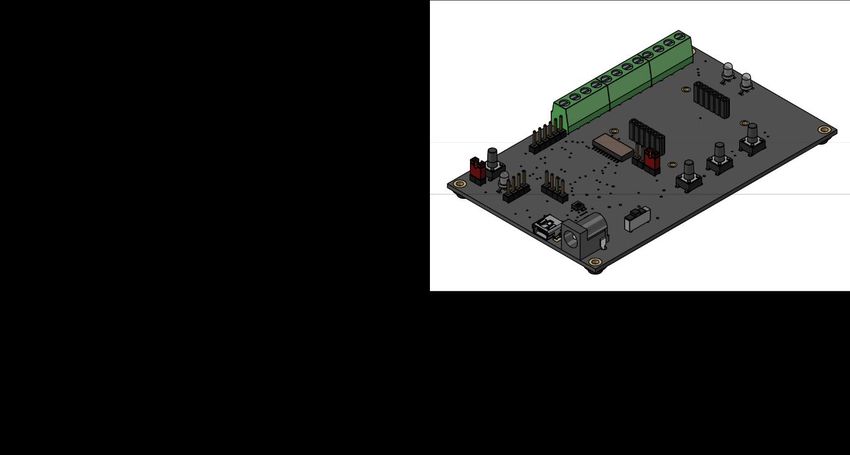
USER GUIDE

                                                Figure 2: Top Side Evaluation Board

                                             Figure 3: Bottom Side Evaluation Board

Gas Sensing Solutions Ltd.                                                               Revision 1.2, 29 March 2021

Page | 7   For regular updates, sign up at https://gassensing.co.uk                   Copyright © 2021 Gas Sensing Solutions Ltd.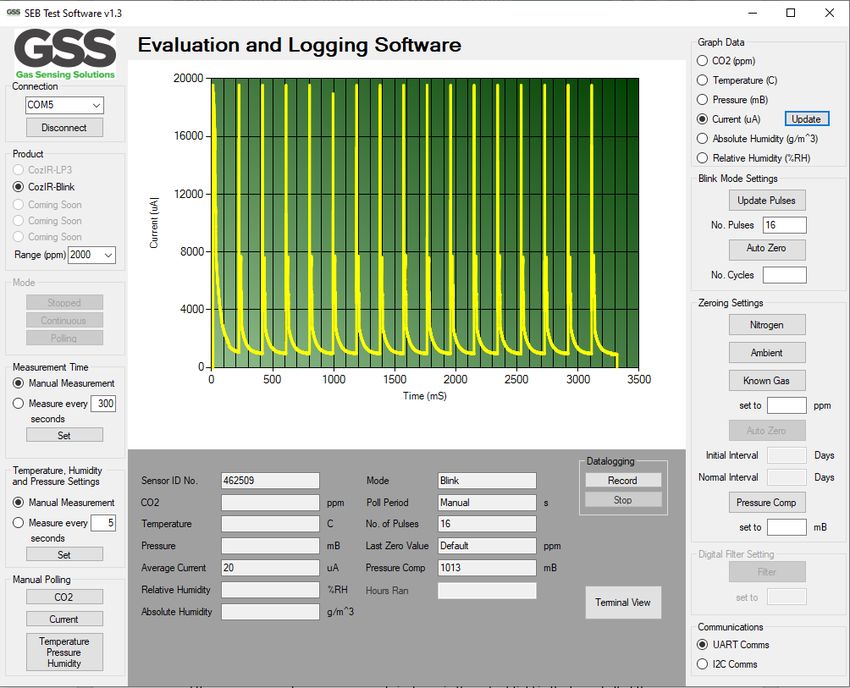
USER GUIDE

STANDALONE OPERATION
The sensor can be completely isolated from the rest of the evaluation board electronics. This allows
the user to conveniently control the sensor directly via edge connectors J3, J4 and J5. To operate in
this manner, the DIP switches (S5) must be set to isolate the sensor from the microcontroller by
putting them into the off position.

                                   Figure 4: DIP Switches (S5, shown in OFF position)

The evaluation board is shipped with the DIP switches set ON (see label on switch) to connect the
sensor to the on-board microcontroller by default. To isolate the sensor from the on-board
microcontroller, set the switches to OFF. Power supply connections to the sensor are described in
the following section.

The sensor switch connections on the DIP switches are listed below.

 SWITCH POSITION               NAME                        TYPE                   DESCRIPTION
 1                             Rx_In                       Digital Input          UART Receive Input
 2                             Tx_Out                      Digital Output         UART Transmit Output
 3                             NC                          Unused                 Do not connect (For internal use only)
 4                             VDD1                        Supply                 Sensor supply voltage
 5                             NC                          Unused                 Do not connect
 6                             READY                       Digital Output         Data ready pin. Pulsed high when data
                                                                                  ready
 7                             I2C_SDA                     Digital Input/Output   I2C serial data input/output. Pull-up
                                                                                  resistor to VDD is provided on the
                                                                                  evaluation board.
 8                             I2C_SCL                     Digital Input          I2C serial clock input. Pull-up resistor to
                                                                                  VDD is provided on the evaluation
                                                                                  board.
 9                             I2C_ENABLE                  Digital Input          Set low for I2C interface mode. Leave
                                                                                  floating to select UART interface mode.
                                                                                  Pin status detected at power on.
 10                            NC                          Unused                 Do not connect

Gas Sensing Solutions Ltd.                                                                      Revision 1.2, 29 March 2021

Page | 8   For regular updates, sign up at https://gassensing.co.uk                          Copyright © 2021 Gas Sensing Solutions Ltd.
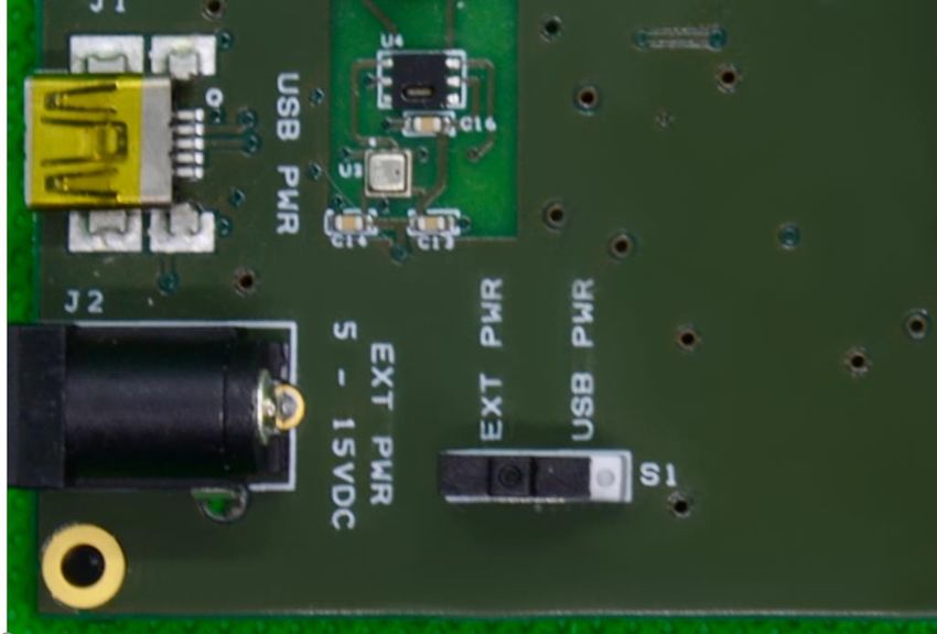
USER GUIDE

SENSOR POWER SUPPLY
If the sensor is to be evaluated in isolation and separately from the evaluation board USB interface
and software, it must be provided with power. There are three methods to provide power to the
sensor. In all cases, the CozIR®-Blink-N must be powered cycled to function correctly. The CozIR®-
Blink-N is pre-programmed to take a single reading per power cycle. This means that power to the
sensor must be removed and re-applied before the sensor will take another reading.

Note the sensor must be powered via the USB interface (method 2) if the GSS evaluation software is
to be used.

Method 1 - External Power Supply
The sensor can be supplied from an external power source via the connector (J2). This connector
can accept either a 2.5mm or 2.1mm standard DC 5V power supply barrel plug. This drives a low
noise low drop out (LDO) regulator, which supplies the sensor via a FET switch.

The LDO regulator provides a stable 3.3V output to the sensor via switch S1. To enable this mode of
operation, switch S1 should be set to external power (EXT PWR). The LDO input voltage range is a
nominal 5V to 15V.

Power is only connected to the sensor when switch S2 is pressed. Sensor data must be read out from
the sensor when switch S2 is on. Releasing switch S2 will cut-off the power to the sensor.

In this mode, sensor data can only be retrieved from the sensor using the data interface on
connectors J3, J4 and J5. Please ensure the PL1 jumper is fitted.

Method 2 - USB Power Supply
Power is normally provided by a USB source. Plug J1 into a USB power source and set switch S1 to
USB power (USB PWR), see picture below. This drives a low noise low drop out (LDO) regulator,
suppling the sensor via a FET switch. The LDO regulator provides a stable 3.3V output to the sensor.

Gas Sensing Solutions Ltd.                                                   Revision 1.2, 29 March 2021

Page | 9   For regular updates, sign up at https://gassensing.co.uk       Copyright © 2021 Gas Sensing Solutions Ltd.
USER GUIDE

Method 3 - Variable External Power Supply
The user can also drive the sensor directly with an external power supply, bypassing the on-board
low noise LDO and FET switch. This allows the user to evaluate the behaviour of the sensor with
different supply voltages or power sources. To enable this mode of operation, the following settings
need to be configured.

 Connector/Jumper                        Setting                               Sensor Connection
 J5, pin 1                               Connect to external GND               GND
 J5, pin 2                               Connect to external VDD               VDD
 J5, pin 4                               Connect to external VDD               VDD1
 PL1                                     Remove jumper. Isolates sensor from   -
                                         rest of the evaluation board
 PL2                                     Remove jumper. Isolates sensor from   -
                                         rest of the evaluation board

The evaluation board has pull-up resistors for the I2C serial data input/output lines in each of these
modes. They pull-up to either the on-board 3.3V supply, or the external VDD on J5, pin 2 and pin 4.

All the sensor connections are enumerated on connectors, J3, J4 and J5, see figure 1. For a full
description of the sensor connections and functions, please refer to the latest version of the data
sheet at, https://www.gassensing.co.uk/products/.

Note that for the CozIR®-Blink-N to operate correctly in this mode, the external supply connections
on J5, pin 2 and pin 4 must be power-cycled. This means that all power to the sensor must be
removed, and then re-applied. The CozIR®-Blink-N will only take a new reading after it has been
power cycled. The time between a power down and re-application of power should be greater than 4
seconds to ensure the sensor is fully switched off. This will ensure the sensor is properly power
cycled. Failure to allow the sensor adequate time to power down may result in erratic performance.

Gas Sensing Solutions Ltd.                                                            Revision 1.2, 29 March 2021

Page | 10   For regular updates, sign up at https://gassensing.co.uk               Copyright © 2021 Gas Sensing Solutions Ltd.
USER GUIDE
J3
PIN NAME TYPE DESCRIPTION
1 I2C_SCL Digital Input I2C serial clock input. Open drain, external 3.3kΩ
resistor pulled high to VDD required
2 I2C_SDA Digital I2C serial data input/output. Open drain, external
Input/Output 3.3kΩ resistor pulled high to VDD required
3 Tx_Out Digital Output UART Transmit Output
4 Rx_In Digital Input UART Receive Input
J4
PIN NAME TYPE DESCRIPTION
1 NC Unused Do not connect
2 READY Digital Output Data ready pin. Pulsed high when data ready
3 NC Unused Do not connect (For internal use only)
4 I2C_ENABLE Digital Input Set low for I2C interface mode. Leave floating to
select UART interface mode. Pin status detected at
power on.
J5
PIN NAME TYPE DESCRIPTION
1 GND Supply Sensor ground
2 VDD Supply Sensor supply voltage
3 NC Unused Do not connect (For internal use only)
4 VDD1 Supply Sensor supply voltage
Gas Sensing Solutions Ltd. Revision 1.2, 29 March 2021
Page | 11 For regular updates, sign up at https://gassensing.co.uk Copyright © 2021 Gas Sensing Solutions Ltd.USER GUIDE
SENSOR POWER CONSUMPTION MEASUREMENT
The sensor evaluation board contains circuitry to allow the user to accurately measure sensor
current consumption. A high-precision, high-side current-sense amplifier is used to measure the
current through a 1.5ohm resistor R6. The signal is digitised by the on-board microcontroller.
The application software graphically displays the current draw of the sensor over the initial part of
the measurement cycle and displays the average current draw whilst it is powered up. The sensor
power consumption measurement application operates when using sensor power method 2. It
cannot be used when powering the sensor using method 1 or 3.
ENVIRONMENTAL CONDITION MONITORING
In addition to CO2 measurement, the sensor evaluation board comes with the ability to measure
relative humidity, temperature, and pressure in real time. These functions operate independently of
the CO2 sensor. The application software displays and can store these conditions. The evaluation
board must be powered either via the USB interface (method 2), or the external power supply
(method 1).
EVALUATION BOARD BUTTONS, JUMPERS AND LED INDICATORS
BUTTON DESCRIPTION
S1 USB power or external power
S2 Blink mode. Applies power temporarily to the sensor (using method 1 or method 2).
Note switch is non-latching. Press to apply power, release to remove power.
S3 Unused
S4 Unused
S5 Evaluation board micro to sensor interface
S6 Reset MCU
JUMPER DESCRIPTION
PL1 Enables power to the sensor using switch S2.
PL2 Allows sensor to be isolated from USB or S1 power connections. Remove jumper if
using external power via J5
LED DESCRIPTION
LED1 Green. Shows Evaluation board is running
LED2 Green. Shows transmission of data to the board in UART mode
Red. Shows transmission of data to the board in I2C mode
LED3 Green. Shows transmission of data from the sensor in UART mode
Red. Shows transmission of data from the sensor in I2C mode
Gas Sensing Solutions Ltd. Revision 1.2, 29 March 2021
Page | 12 For regular updates, sign up at https://gassensing.co.uk Copyright © 2021 Gas Sensing Solutions Ltd.USER GUIDE SOFTWARE USER INTERFACE All the main sensor and evaluation board functions are controlled through a single user interface, displayed above. Hovering over a button will display the tips for that function. Gas Sensing Solutions Ltd. Revision 1.2, 29 March 2021 Page | 13 For regular updates, sign up at https://gassensing.co.uk Copyright © 2021 Gas Sensing Solutions Ltd.
USER GUIDE

RUNNING THE SOFTWARE
The software may start automatically after installation. If it does not, you can start it from the
“Program” Menu in the Start Menu. Look for the filename GSS Customer Evaluation Board. The
opening screen is below.

To connect to the sensor, select the correct COM port from the drop-down Connection list, and
click the CONNECT button. The drop-down list will only show ports with active devices attached.

If you do not know the appropriate port select “device manager” on your PC, select Ports, and
unplug the SEB and then plug back in. The Com port will show up when the board is plugged in.

Gas Sensing Solutions Ltd.                                                   Revision 1.2, 29 March 2021

Page | 14   For regular updates, sign up at https://gassensing.co.uk      Copyright © 2021 Gas Sensing Solutions Ltd.
USER GUIDE

SENSOR SELECTION

Select the correct sensor type and the full-scale range (CO2 ppm) of the sensor.

The power LED1 will illuminate green showing the sensor evaluation board is running.

Gas Sensing Solutions Ltd.                                                   Revision 1.2, 29 March 2021

Page | 15   For regular updates, sign up at https://gassensing.co.uk      Copyright © 2021 Gas Sensing Solutions Ltd.
USER GUIDE

CO2 SENSOR MEASUREMENT

The CozIR®-Blink-N sensor is pre-programmed to automatically take a series of measurements, filter
the data, and output a single reading after power is applied. After completion of this process, the
CozIR®-Blink-N will automatically enter a low power state. The CozIR®-Blink-N will not take any
further measurements until after a power cycle.

The software interface allows the user to cycle the power at a set period, or to manually power cycle
the CozIR®-Blink-N. In both cases, the sensor is powered off as soon as it has completed the
measurement cycle. The power-on time is dependent on the ‘nPulse’ value. The time period is
between power on events.

To power cycle at a set period, select ‘Measure every seconds’, enter the required power cycle
period and press Set. Note the minimum period is also dependent on the ‘nPulse’ setting, see Blink
Mode Settings.

Gas Sensing Solutions Ltd.                                                  Revision 1.2, 29 March 2021

Page | 16   For regular updates, sign up at https://gassensing.co.uk     Copyright © 2021 Gas Sensing Solutions Ltd.
USER GUIDE

The CozIR®-Blink-N takes a number of measurements and filters them to create a single reading.
Each measurement takes 200ms plus the sensor setup time. For an ‘nPulse’ setting of 16, the time
to report a reading is approximately 16*200ms + 300ms = 3.5s. If the time required by the sensor to
report a valid reading is lower than the minimum cycle time, the software will not accept the value
and the user will be reminded of the minimum value allowable for the ‘nPulse’ setting. After the
sensor has reported a valid reading, it is automatically powered down by the software.

To power cycle the sensor manually, set ‘Measurement Time’ to Manual Measurement. The sensor
will be power cycled, and a new reading will be taken when the user clicks ‘Manual Polling – CO2’.
Manually power cycling the sensor faster than the minimum time needed to create a valid reading
will result in erratic sensor performance.

After a manual power cycle, or after each power cycle period, the CO2 reading will be updated in the
main sensor data display area.

Gas Sensing Solutions Ltd.                                                  Revision 1.2, 29 March 2021

Page | 17   For regular updates, sign up at https://gassensing.co.uk     Copyright © 2021 Gas Sensing Solutions Ltd.
USER GUIDE

OTHER ENVIRONMENTAL SENSORS

The evaluation board also contains on-board temperature, humidity, pressure, and current sensors.
These can be set to take measurements automatically at a pre-set period or set to take readings
manually. Note the time period can be set independently of the CO2 sensor read period.

For manual readings, click ‘Manual Measurement’. Manual readings can be taken for each sensor
including the CO2 sensor by clicking on the relevant button. The user interface in the lower centre of
the screen will update each sensor value when ‘Manual Measurement’ is clicked.

Alternatively, the sensors can be programmed to take readings continuously at the rate set in the
dialogue box. Click on the ‘Measure every 5 seconds box’, set the measurement period and click on
‘Set’.

The user interface in the lower centre of the screen will update every time period.

Gas Sensing Solutions Ltd.                                                   Revision 1.2, 29 March 2021

Page | 18   For regular updates, sign up at https://gassensing.co.uk      Copyright © 2021 Gas Sensing Solutions Ltd.
USER GUIDE

CURRENT MEASUREMENT

To measure current, the sensor must be in ‘Manual Measurement’ mode.

The current measurement function generates a real time graphical display of the current
consumption of the sensor.

To correctly measure average current, the period between power cycles must be specified. This is
done by entering a value in the ‘Measure every seconds’ box. In the example shown, the period is
300 seconds between power on events.

To measure average current, click on ‘Update’ Current (uA) in the Graph Data section.

The ‘Average Current’ displayed in the lower centre of the screen is the current consumed by the
sensor over a complete 300s power cycle period. Thus, the average current is defined as the current
consumed by the sensor during the measurement period when it is powered up (period defined by
the nPulse setting) divided by the total time between power on events.

Note that the sensor is powered down as soon as the CO2 reading has been accessed by the host
controller.

Gas Sensing Solutions Ltd.                                                 Revision 1.2, 29 March 2021

Page | 19   For regular updates, sign up at https://gassensing.co.uk    Copyright © 2021 Gas Sensing Solutions Ltd.
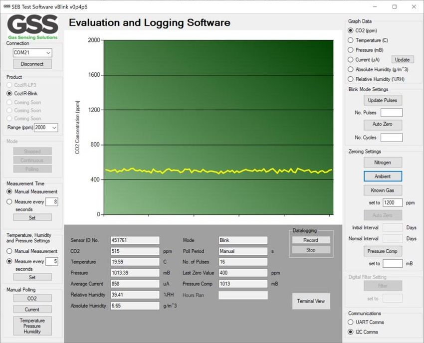
USER GUIDE

GRAPHING SENSOR DATA

The user can graph sensor data. Click on the appropriate sensor box to graph the data in the upper
central area of the user interface. Note, only one sensor can be graphed at a time.

The graph update rate is set to the measurement rate, defined by the ‘Measurement Time’ of the
CO2 sensor, or by the Temperature, Humidity and Pressure Settings.

When the current graph is selected, the evaluation board will accurately measure and graph the
current consumed by the sensor over the measurement period. This can be updated by clicking the
update button or manually polling using the ‘Current’ button. The key activity period is displayed
and the average current per power on cycle is shown in the output field in the lower half of the
display.

To perform current measurement, the automatic power cycling must not be selected. Unclick
‘Measure every seconds’ to disable this function. If the user tries to undertake current
measurement, the software will warn the user and not allow an update to be made. After a current
measurement, automatic power cycling can be re-enabled.

Gas Sensing Solutions Ltd.                                                 Revision 1.2, 29 March 2021

Page | 20   For regular updates, sign up at https://gassensing.co.uk    Copyright © 2021 Gas Sensing Solutions Ltd.
USER GUIDE

ZERO-POINT SETTING THE SENSOR

There are a several methods available to the user to set the zero point of the sensor. In all cases, the
best zero is obtained when the gas concentration is stable, and the sensor is at a stable temperature.
Note the zero-point settings are not cumulative and only the latest zero-point setting is effective. For
example, there is no benefit in zeroing in nitrogen, and then zeroing in a calibration gas. The sensor
will store only the latest zero point.

Gas Sensing Solutions Ltd.                                                    Revision 1.2, 29 March 2021

Page | 21   For regular updates, sign up at https://gassensing.co.uk       Copyright © 2021 Gas Sensing Solutions Ltd.
USER GUIDE

ZERO IN NITROGEN
Place the sensor in nitrogen gas and allow time for the sensor to stabilise and the gas to be fully
diffused into the sensor. Click on ‘Nitrogen’. The sensor will be zeroed assuming a 0ppm CO2
environment.

ZERO IN AMBIENT CONDITIONS
If there is no calibration gas or nitrogen available, the sensor zero-point can be set in fresh air.
Ambient CO2 concentrations in fresh air are typically 400ppm. Place the sensor in a fresh air
environment and allow time for the sensor temperature to stabilise, and for the fresh air to be fully
diffused into the sensor. If there is no value in the ‘Set to’ dialogue box, when ‘Ambient’ is clicked,
the sensor will be zeroed assuming the ambient environment is 400ppm.

The CO2 concentration fresh air zero level is programmable over a range from 0ppm to the full scale
of the sensor. The software default is 400ppm as the fresh air CO2 concentration value. However,
the user can write a different fresh air value to the sensor if desired.

To write a different fresh air CO2 concentration value to the sensor, set the CO2 concentration value
to the appropriate value by writing the value in the ‘set to’ box. Click on ‘Ambient.

ZERO IN A KNOWN GAS CONCENTRATION
Place the sensor in a known gas concentration, and allow time for the sensor temperature to
stabilise, and for the gas to be fully diffused into the sensor. Set the CO2 concentration value to the
appropriate value by writing the value in the ‘set to’ box. Click on ‘Known Gas’.

In all cases the sensor polling mode needs to be switched off during the change. The software will
warn the user if this is not selected. After the change has been made polling mode can be re-
enabled.

Gas Sensing Solutions Ltd.                                                    Revision 1.2, 29 March 2021

Page | 22   For regular updates, sign up at https://gassensing.co.uk       Copyright © 2021 Gas Sensing Solutions Ltd.
USER GUIDE

PRESSURE COMPENSATION

GSS sensors are calibrated at a nominal 1013mbar. The CO2 reading from the sensor will vary from
the nominal output if the mean barometric pressure is different from the calibration setting.

It is possible to configure the sensor to correct for this effect by writing the actual or reference mean
barometric pressure in mbar to the sensor. This can be done as part of the initial set up process or
updated at any time during use. Write the decimal value in mbar into the dialogue box and click
‘Pressure Comp’.

In all cases the sensor polling mode needs to be switched off during the change. The software will
warn the user if this is not selected. After the change has been made polling mode can be re-
enabled.

Gas Sensing Solutions Ltd.                                                     Revision 1.2, 29 March 2021

Page | 23   For regular updates, sign up at https://gassensing.co.uk        Copyright © 2021 Gas Sensing Solutions Ltd.
USER GUIDE

BLINK MODE SETTINGS

The CozIR®-Blink-N is pre-programmed to start taking measurements at a pre-set rate of 200msec
after power is applied to the sensor. These measurements are filtered to create a single reading that
is stored in sensor memory. Once this reading has been stored in memory, the sensor will stop
taking measurements. No more measurements will be taken until the sensor has been power-
cycled.

The number of measurements used to create a single filtered value is determined by setting the
‘nPulse’ value. Set ‘nPulse’ by entering the value into the ‘No. Pulses’ data entry box.

The default value is 16. Reducing the nPulse value decreases the time taken to acquire the reading
but at the expense of measurement noise. Each value of nPulse is equivalent to one 200msec
measurement. Therefore, the value of nPulse also sets how long the sensor takes to acquire a
reading.

In all cases, the sensor automatic power cycling mode needs to be switched off during the change.
Unclick the ‘Measure every seconds’. The software will warn the user if this is not done. After the
change has been made, automatic power cycling can be re-enabled by clicking the ‘Measure every
seconds’ function and entering a time value in the box.

Gas Sensing Solutions Ltd.                                                  Revision 1.2, 29 March 2021

Page | 24   For regular updates, sign up at https://gassensing.co.uk     Copyright © 2021 Gas Sensing Solutions Ltd.
USER GUIDE

AUTO-ZERO FUNCTION
The sensor has a built-in auto-zeroing function. To function correctly, the sensor must be exposed to
typical background fresh air levels (~400ppm) at least once during the auto-zero period. The auto-
zero function uses the information gathered during these periods to re-zero. The sensor will reset
the ‘zero’ level every time it does an auto-zero. Auto-zeroing is enabled by default. If the sensor is
powered down, the auto-zero is reset to default fresh air value, 400ppm. The user can change this
default value.

The auto-zero function works in the same way as the ‘Ambient’ command.

AUTO-ZERO INTERVALS
The auto-zero period can be programmed by the user. For the CozIR®-Blink-N, an auto-zero is set
based on the number of sensor power cycles. Add the number of power cycles in the ‘No. Cycles’
data entry box and click ‘Auto Zero’.

AUTO-ZERO LEVEL
The background concentration will depend on sensor location. Ambient levels are typically in the
range of 400ppm - 450ppm. The factory default is set to 400ppm. The user can change the
background ambient level used for auto-zeroing. The value is stored in the sensor.

Typically, it is set to the same value as the ambient value, but it can also be set at a different level if
desired. To write a different fresh air CO2 concentration value to the sensor used for auto-zeroing,
the command must be sent to the sensor manually using the software terminal mode. For more
details on how to adjust the auto-zero fresh air CO2 concentration value, see the full data sheet at
https://www.gassensing.co.uk/products/.

Gas Sensing Solutions Ltd.                                                       Revision 1.2, 29 March 2021

Page | 25   For regular updates, sign up at https://gassensing.co.uk          Copyright © 2021 Gas Sensing Solutions Ltd.
USER GUIDE

SENSOR COMMUNICATIONS

The sensor has two control interface modes. To ensure the sensor behaviour is representative of
real-world use, the evaluation board microprocessor will communicate with the sensor in either
UART or I2C mode dependent on this setting. To set the interface mode, click on the appropriate
dialogue box.

Power cycling is automatically disabled during changes. It can be manually enabled after the change.

Gas Sensing Solutions Ltd.                                                 Revision 1.2, 29 March 2021

Page | 26   For regular updates, sign up at https://gassensing.co.uk    Copyright © 2021 Gas Sensing Solutions Ltd.
USER GUIDE

DATA DISPLAY

Essential sensor data is displayed numerically in the lower half of the user interface.

 Sensor Data Type                           Description                                 Units
 Sensor ID No.                              Unique sensor ID                            N/A
 CO2                                        CO2 concentration                           ppm
 Temperature                                Ambient temperature                         °C
 Pressure                                   Ambient pressure                            mbar
 Average Current                            Current drawn by the sensor over a power    uA
                                            cycle period – see description for more
                                            details.
 Relative Humidity                          Ambient relative humidity                   %RH
 Absolute Humidity                          Ambient absolute humidity                   grams per cubic metre

This data is updated depending on the measurement mode of the sensors.

Gas Sensing Solutions Ltd.                                                                Revision 1.2, 29 March 2021

Page | 27   For regular updates, sign up at https://gassensing.co.uk                   Copyright © 2021 Gas Sensing Solutions Ltd.
USER GUIDE Sensor Data Type Description Units Mode Measurement mode Poll Period Measurement update period Seconds Filter Digital filter setting Decimal Last Zero Value Value used to re-zero the sensor ppm Pressure Comp Pressure value used by CO2 sensor mbar Hours Ran No value This data is static and represents the configuration of the CO2 sensor. Gas Sensing Solutions Ltd. Revision 1.2, 29 March 2021 Page | 28 For regular updates, sign up at https://gassensing.co.uk Copyright © 2021 Gas Sensing Solutions Ltd.
USER GUIDE

DATALOGGING

CO2 and other sensor data can be recorded. To initiate the recording process, click ‘Record’. To stop
the recording process, click ‘Stop’.

Clicking on ‘Record’ brings up the following screen.

Gas Sensing Solutions Ltd.                                                  Revision 1.2, 29 March 2021

Page | 29   For regular updates, sign up at https://gassensing.co.uk     Copyright © 2021 Gas Sensing Solutions Ltd.
USER GUIDE

The user can select where the file is stored and directly type in the file name.

The data will be recorded as a .csv file that can subsequently be opened in a spreadsheet program.
The sensor data will be timestamped, allowing easy analysis of all environmental parameters. The
measurement period for each sensor type follows the settings on the user interface.
                                Recorded by GSS Sensor Evaluation Board
                                       13/01/2021 11:36
                                                 451761
                                Timestamp               CO2 ppm             Temperature C       Pressure mB         %RH           AH g/m^3
                                 13/01/21 11:36:07.113                 1231
                                 13/01/21 11:36:14.122                 1177
                                 13/01/21 11:36:21.115                 1216
                                 13/01/21 11:36:28.108                 1196
                                 13/01/21 11:36:40.478                 1205               23.96             1014.38       35.38               7.68
                                 13/01/21 11:36:40.483                                    23.96             1014.38       35.38               7.68
                                 13/01/21 11:36:49.486                 1187
                                 13/01/21 11:36:53.664                                    23.98             1014.37       35.39               7.69
                                 13/01/21 11:36:58.480                 1184
                                 13/01/21 11:37:07.473                 1221
                                 13/01/21 11:37:08.673                                       24             1014.38       35.48               7.72
                                 13/01/21 11:37:16.466                 1222
                                 13/01/21 11:37:25.475                 1216
                                 13/01/21 11:37:25.491                                    24.02             1014.38       35.37                7.7
                                 13/01/21 11:37:34.484                 1205
                                 13/01/21 11:37:38.661                                    24.03             1014.35       35.43               7.72
                                 13/01/21 11:37:43.478                 1210
                                 13/01/21 11:37:52.471                 1215
                                 13/01/21 11:37:53.671                                    24.05             1014.35       35.25               7.69
                                 13/01/21 11:38:01.464                 1249
                                 13/01/21 11:38:10.490                 1239               24.06             1014.36       35.31               7.71
                                 13/01/21 11:38:10.492                                    24.06             1014.36       35.31               7.71
                                 13/01/21 11:38:19.483                 1237
                                 13/01/21 11:38:23.660                                    24.08             1014.35       35.46               7.75
                                 13/01/21 11:38:28.476                 1239
                                 13/01/21 11:38:37.485                 1236
                                 13/01/21 11:38:38.670                                    24.09             1014.36       35.39               7.74
                                 13/01/21 11:38:46.478                 1248
                                 13/01/21 11:38:55.488                 1264
                                 13/01/21 11:38:55.504                                     24.1             1014.39       35.22               7.71
                                 13/01/21 11:39:04.497                 1215
                                 13/01/21 11:39:08.674                                    24.12              1014.4       35.15                7.7

The above table shows the CO2 sensor ID451761, with different data recorded at different rates.

Gas Sensing Solutions Ltd.                                                                                                               Revision 1.2, 29 March 2021

Page | 30   For regular updates, sign up at https://gassensing.co.uk                                                                  Copyright © 2021 Gas Sensing Solutions Ltd.
USER GUIDE TERMINAL VIEW Access to all CO2 sensor functions and register settings are available to the user using the Terminal View. The Terminal View allows the user to read and write directly to the CO2 sensor. For a Blink-N sensor to accept commands the sensor MUST NOT be in polling mode. Before sending any commands to the sensor, it must be power cycled using the ‘reset’ button in the Terminal View window. The Terminal View window will show S0 followed by S1 to say that it has been power- cycled correctly. Gas Sensing Solutions Ltd. Revision 1.2, 29 March 2021 Page | 31 For regular updates, sign up at https://gassensing.co.uk Copyright © 2021 Gas Sensing Solutions Ltd.
USER GUIDE

TERMINAL VIEW – UART READ
To open the terminal window for UART communications, first ensure that ‘UART Comms’ has been
selected under the ‘Communications’ menu. Before reading from or writing to the UART interface,
press the ‘Reset’ button.

The S0 and S1 indicate that a power-cycle has occurred after selecting the Reset button. A ‘Z’
command must be sent first in UART mode. Sending the ‘Z’ command clears the C02 value giving the
??? response. Once the sensor has responded with ???, standard commands may be sent to the
sensor via the terminal window.

To read a value, write the command into the dialogue box, and click ‘Send.

Examples of commands are shown above.

‘a’ is the returned value for the npulse setting. In this case, the value is 16.

‘s’ is the returned value of the altitude compensation factor. In this case, the sensor is returning the
default of 8192.

By pressing the ‘Debug’ button, a command is sent to return the sensor settings as above. This
returns information on the state of the sensor, including sensor ID (451784).

Gas Sensing Solutions Ltd.                                                         Revision 1.2, 29 March 2021

Page | 32   For regular updates, sign up at https://gassensing.co.uk          Copyright © 2021 Gas Sensing Solutions Ltd.
USER GUIDE

TERMINAL VIEW – UART WRITE
Write the command into the dialogue box and click ‘Send. In this example, the X Command is
shown. X is the command to zero the sensor in a known gas concentration, in this case 1000ppm.
Sending a command followed by an integer (X 1000 in this case) will write the value into the
appropriate register. The sensor will automatically respond with an internal reference variable
decimal value corresponding to that setting.

Gas Sensing Solutions Ltd.                                                Revision 1.2, 29 March 2021

Page | 33   For regular updates, sign up at https://gassensing.co.uk   Copyright © 2021 Gas Sensing Solutions Ltd.
USER GUIDE

TERMINAL VIEW – I2C WRITE
To open the terminal window for I2C communications, first ensure that ‘I2C Comms’ has been
selected under the ‘Communications’ menu. Before reading from or writing to I2C registers, press
the ‘Reset’ button.

The S0 and S1 indicate that a power-cycle has occurred after selecting the Reset button.

To write to an I2C register, the instruction must be formatted correctly.

Writes are formatted as “%wr”, followed by the number of bits to write, followed by the register
number in decimal, followed by the decimal value to write to the register.

For example: “%wr8 5 1” will write the value 1 (as an 8-bit word) to register 5, which will zero the
sensor in ambient conditions as per the datasheet.

An OK will be returned showing that the command has been accepted.

Note the debug button does not function in I2C mode.

Gas Sensing Solutions Ltd.                                                     Revision 1.2, 29 March 2021

Page | 34   For regular updates, sign up at https://gassensing.co.uk        Copyright © 2021 Gas Sensing Solutions Ltd.
USER GUIDE

TERMINAL VIEW – I2C READ

To read from an I2C register, the instruction is formatted as “%rd” followed by the number of bits to
read as noted in the datasheet, followed by the register number in decimal.

For example: “%rd16 2” will read 16 bits from register 2, which in this case will return the CO2 value
in ppm.

Gas Sensing Solutions Ltd.                                                    Revision 1.2, 29 March 2021

Page | 35   For regular updates, sign up at https://gassensing.co.uk       Copyright © 2021 Gas Sensing Solutions Ltd.
USER GUIDE

The “%” in the I2C commands denotes to the evaluation board that a special command must be pre-
processed before passing on to the sensor. If the interface is set to I2C mode, and if the % is missing,
the evaluation board assumes the command is a UART command and sending it on to the sensor will
return a timeout.

Gas Sensing Solutions Ltd.                                                    Revision 1.2, 29 March 2021

Page | 36   For regular updates, sign up at https://gassensing.co.uk       Copyright © 2021 Gas Sensing Solutions Ltd.
USER GUIDE

MECHANICAL DIAGRAM

Gas Sensing Solutions Ltd.                                                Revision 1.2, 29 March 2021

Page | 37   For regular updates, sign up at https://gassensing.co.uk   Copyright © 2021 Gas Sensing Solutions Ltd.
USER GUIDE

IMPORTANT NOTICE
Gas Sensing Solutions Ltd. (GSS) products and services are sold subject to GSS’s terms and conditions of sale,
delivery and payment supplied at the time of order acknowledgement. GSS warrants performance of its
products to the specifications in effect at the date of shipment. GSS reserves the right to make changes to its
products and specifications or to discontinue any product or service without notice.

Customers should therefore obtain the latest version of relevant information from GSS to verify that the
information is current. Testing and other quality control techniques are utilised to the extent GSS deems
necessary to support its warranty. Specific testing of all parameters of each device is not necessarily
performed unless required by law or regulation. In order to minimise risks associated with customer
applications, the customer must use adequate design and operating safeguards to minimise inherent or
procedural hazards. GSS is not liable for applications assistance or customer product design. The customer is
solely responsible for its selection and use of GSS products. GSS is not liable for such selection or use nor for
use of any circuitry other than circuitry entirely embodied in a GSS product.

GSS products are not intended for use in life support systems, appliances, nuclear systems or systems where
malfunction can reasonably be expected to result in personal injury, death or severe property or
environmental damage. Any use of products by the customer for such purposes is at the customer’s own risk.

GSS does not grant any licence (express or implied) under any patent right, copyright, mask work right or other
intellectual property right of GSS covering or relating to any combination, machine, or process in which its
products or services might be or are used. Any provision or publication of any third party’s products or
services does not constitute GSS’s approval, licence, warranty or endorsement thereof. Any third party trade-
marks contained in this document belong to the respective third-party owner.

Reproduction of information from GSS datasheets is permissible only if reproduction is without alteration and
is accompanied by all associated copyright, proprietary and other notices (including this notice) and
conditions. GSS is not liable for any unauthorised alteration of such information or for any reliance placed
thereon.

Any representations made, warranties given, and/or liabilities accepted by any person which differ from those
contained in this datasheet or in GSS’s standard terms and conditions of sale, delivery and payment are made,
given and/or accepted at that person’s own risk. GSS is not liable for any such representations, warranties or
liabilities or for any reliance placed thereon by any person.

ADDRESS

Gas Sensing Solutions Ltd.
Grayshill Road
Cumbernauld
G68 9HQ
United Kingdom

Gas Sensing Solutions Ltd.                                                            Revision 1.2, 29 March 2021

Page | 38   For regular updates, sign up at https://gassensing.co.uk               Copyright © 2021 Gas Sensing Solutions Ltd.
USER GUIDE

REVISION HISTORY
 DATE                   RELEASE                 DESCRIPTION OF CHANGES                PAGES
 16/12/2020             1.0                     First revision                        All
 12/01/2021             1.1                     Major update to all sections          All
 29/03/2021             1.2                     Updated current consumption           P.19

Gas Sensing Solutions Ltd.                                                        Revision 1.2, 29 March 2021

Page | 39   For regular updates, sign up at https://gassensing.co.uk           Copyright © 2021 Gas Sensing Solutions Ltd.
You can also read