DECK PLANS BUILDING DEPARTMENT 763-494-6060 - Maple Grove, MN
←
→
Page content transcription
If your browser does not render page correctly, please read the page content below
DECK
                   PLANS

         BUILDING DEPARTMENT
              763-494-6060
                 www.maplegrovemn.gov
This handout is intended only as a guide and is based in part on the 2020 Minnesota Residential Code (MRC), Maple Grove City
ordinances, and good building practice. While every attempt has been made to insure the correctness of this handout, no guarantees are
made to its accuracy or completeness. Responsibility for compliance with applicable codes and ordinances falls on the owner or
contractor. For specific questions regarding code requirements, refer to MRC section R507 Exterior Decks or contact your local Building
Department.

The following are examples of information that should be included on plans
submitted for building permits for residential decks. They are examples only
and should not be construed as being code compliant for every application. It is
the responsibility of the homeowner or person preparing the plans to show in
detail how they will build their deck. Some designs may require more detail than
others.

Your deck plans should replicate exactly how you will build your deck. We will
review your plans before we issue the building permit before you start work.
The more detailed your plans, the more likely you avoid corrections in the field.

When you receive your permit, you will also be given one set of plans stamped
“Approved”. Once your plans are approved, you should not change your design
without approval by the Maple Grove Building Department. Read through the
approved plans to determine if the plan reviewer noted any corrections to
your plan. If you have any questions regarding any of the corrections, you
should contact us before proceeding. Our inspections will require these
corrections are addressed at time of inspections.

The City of Maple Grove has a detailed handout on deck construction and it is
recommended that you obtain a copy of the handout for further direction.

                                                                 Page 1                                          Rev. 04/12/2021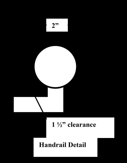
CHECKLIST FOR DECK PLANS
Site Plan                                                 Section(s)
   Street address and/or legal description shown                Section view(s) from bottom of footing to top of guard
   North arrow shown                                            to show railing details; floor framing orientation;
   Plan drawn to useable scale and scale used                   joist/beam orientation and bearing; column locations;
   shown                                                        connections; footing design, size, and depth; and
   Size of existing buildings shown                             height of deck floor above grade.
   All lot dimensions and pin locations shown
   Location and size of proposed deck shown               Details
   Distance to all lot lines from existing buildings          Flashing at the ledger
   and proposed deck                                          Joist bearing/hangers
                                                              Ledger connection (Caution for dwelling floor
Construction Plans                                        cantilevers)
   Plans drawn to useable scale                               Fasteners/connectors consistent with lumber and
   Scale indicated on plan                                decking used
   Plan neat and legible                                      Column/beam connection
                                                              Column/footing connection
Elevation (This could be illustrated on                       Type of decking and orientation (Caution for 5/4 or
section drawings)                                         composite decking for spans more than 16” o.c. or
   Show side and front view of deck in relation to        installed diagonally
   grade and dwelling                                         Research report required for decking other than wood
   Include railing height and design                          Stair stringer connection
                                                              Lateral bracing
Framing Plan
   Floor joist size and spacing including species         Stairs
and grade                                                     Width of stairs
   Orientation of floor joists                                Rise/run w/tolerance shown
   Cantilever of joists                                       Number and size of stringers
   Bearing points for all joists                              Open riser design
   Size and location of all beams including                   Type and size of tread consistent with stringer spacing
   species and grade                                      (Caution for decking use)
   Cantilever of beams                                        Connection method for treads to stringers
   Size and location of ledger board including                Handrails shown for stairs with 4 or more risers
   species and grade                                          Handrail height shown on plan
   Size and location of all columns including                 Handrail profile detailed
   species and grade                                          Landing at bottom of stair
   Track all floor loads thru beams to columns to             Show any doors or windows adjacent stairs and
   footings                                               landings.
   Location of stairs
   Changes in elevation of deck floors or landings        Guards
   Unusual framing issues such as cantilevers of                Guard height and opening dimensions
   the dwelling floor                                           Guard design/materials
                                                                Guard attachment
Ledger Details
   Framing method and orientation of existing
   dwelling floor framing.                                Date: _____________________________________
   Method of meeting lateral load connection
   requirements
   Spacing, location, and type of bolts or lags           Job Address: ______________________________
   used to attach ledger.

Footings (This information may be
included on section or framing plans)
   Footing depth and design
   Footing width at base consistent with load for
   each footing location.

                                                       Page 2                                  Rev. 04/12/2021
***Surveys show
compliance with zoning
setback and lot coverage
requirements, wetland
setbacks, and clearances
to easements. ***
WARNING: THIS IS AN ILLUSTRATION ONLY. IT IS INTENDED TO SHOW SOME OF THE INFORMATION THAT
SHOULD BE INCLUDED ON YOUR DECK PLANS. IT IS NOT INTENDED TO SHOW COMPLIANCE WITH ANY
CODES THAT MAY APPLY. CHANGES IN THE HEIGHT AND SIZE OF A DECK WILL CAUSE VARIATIONS IN CODE
REQUIREMENTS.
Page 3 Rev. 04/12/2021TYPICAL DECK CROSS SECTION
CITY OF MAPLE GROVE Note: All fasteners and
connectors will be compatible
Flashing extended from 5/4 radius edge with materials used.
behind siding over ledger treated decking
board - 2X10 Treated #2 SYP
***Cross sections
provide information
36” High - 2X2 Vert.
on the height above
Rails less than 4 grade of a deck,
inches apart treated details about guards
and certain framing
elements, some
footing information,
and a general
18” Cantilever overview of the deck
Acme #123 Joist construction. ***
hanger approved
for treated wood 2X8 treated 2 – 2X10 treated beam #2 SYP,
joists, 16 o.c. secured to column w/Acme
9’ 8” #2 SYP #ZZTop beam/column connector
½” X 4½” Lag
bolts 16” o.c.
Acme #XYX 6X6 treated Scale ½” = 1’
connector column Column
to pier
Finished 42” Min
grade 8 Inch poured concrete pier
belled to 12 inches at the base
Ledger attachment
WARNING: THIS IS AN ILLUSTRATION ONLY. IT IS INTENDED TO SHOW SOME OF THE INFORMATION THAT SHOULD
BE INCLUDED ON YOUR DECK PLANS. IT IS NOT INTENDED TO SHOW COMPLIANCE WITH ANY CODES THAT MAY
APPLY. CHANGES IN THE HEIGHT AND SIZE OF A DECK WILL CAUSE VARIATIONS IN CODE REQUIREMENTS.
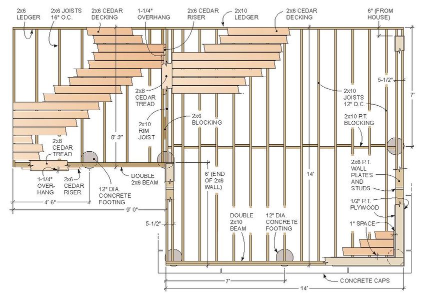
Page 4 Rev. 04/12/2021TYPICAL DECK FLOOR FRAMING PLAN, BEAM LOCATION, AND FOOTING LAYOUT
CITY OF MAPLE GROVE
Floor trusses project 24
inches
Girder let into Acme #2BY beam
dwelling hanger at end of
beam (4 locations)
Acme 246 lateral
load connector at 2x10 Treated Joists
16” o.c. typical, #2
two locations
SYP 10’6”
Install per
manufacturer 12’
install
instructions Beam 2-2X12 treated #2
SYP
Scale ½” = 1’
Stair
details
not
shown
1’ 8’ 8’ 1’
18’ ***Framing plans show the floor
framing and footing layout,
enable checks on spans and
Note about House cantilevers: Occasionally home designs include a cantilever of the floor
system at the patio door. Decks may not be attached to the cantilevered joists unless the house sizing of beams and joists,
floor framing is engineered for the deck loads. validation of footing sizes, and
the ledger design. ***
WARNING: THIS IS AN ILLUSTRATION ONLY. IT IS INTENDED TO SHOW SOME OF THE INFORMATION THAT SHOULD
BE INCLUDED ON YOUR DECK PLANS. IT IS NOT INTENDED TO SHOW COMPLIANCE WITH ANY CODES THAT MAY
APPLY. CHANGES IN THE HEIGHT AND SIZE OF A DECK WILL CAUSE VARIATIONS IN CODE REQUIREMENTS.
Page 5 Rev. 04/12/2021TYPICAL STAIR FRAMING DETAIL
CITY OF MAPLE GROVE
See deck cross
section for
guard design
Top of handrail – 34-38
inches above nosing of
treads. Ends returned
Circular cross section of
1¼ to 2 inches
2X2 Green
treated spindles
Acme #SS strap at 4 3/8” o.c.
to secure stair to
landing Open space
48”
between treads
10” Min less than 4 “ Landing
Run constructed of
7 3/4” Max 2X12 Green treated patio pavers, 36”
Rise, may stair treads min. x width of
not vary stairs
more than
3/8”
Scale ½” = 1’ 3 – 2X12 Green
treated stair jacks,
#2 SYP, verify
***Stair framing details show rise/run manuf. specific #
compliance, guard and handrail of stringers
compliance, connections, materials
used, and general stair design. ***
WARNING: THIS IS AN ILLUSTRATION ONLY. IT IS INTENDED TO SHOW SOME OF THE INFORMATION THAT
SHOULD BE INCLUDED ON YOUR DECK PLANS. IT IS NOT INTENDED TO SHOW COMPLIANCE WITH ANY
CODES THAT MAY APPLY. CHANGES IN THE HEIGHT AND SIZE OF A DECK WILL CAUSE VARIATIONS IN
CODE REQUIREMENTS.
Page 6 Rev. 04/12/2021DOES THIS PLAN LOOK PROFESSIONAL?
THIS IS NOT A SITE PLAN!
?
?
?
• NO LOT LINES ARE SHOWN
• THE DASHED YELLOW LINES HAVE BEEN ADDED FOR INFORMATIONAL
PURPOSES AND ARE THE APPROXIMATE LOCATION OF THE SIDE LOT
LINES.
• NO DIMENSIONS ARE SHOWN (LOT, EXISTING BUILDINGS, PROPOSED
DECK)
• HOW FAR DO YOU THINK THIS DECK IS FROM LOT LINES?
• THE PHOTO IS AN OBLIQUE VIEW OF THE DWELLING. THIS IS
ACTUALLY THE SIDE OF THE HOME.
• IT APPEARS THAT THE DECK MAY BE SOME DISTANCE FROM LOT LINE
WHEN IN FACT IT WAS BUILT TO THE EDGE OF THE DWELLING (ABOUT 8
FEET FROM THE LOT LINE).
• BECAUSE THE PHOTO IS AN OBLIQUE VIEW, IT IS IMPOSSIBLE TO
DETERMINE THE APPROXIMATE LOCATION OF THE PROPOSED DECK
FROM THE PHOTO.
• THE YELLOW DASHED RECTANGLE IS A CLOSER ESTIMATE OF THE
LOCATION OF THE DECK.
YOUR PLANS SHOULD NOT LOOK LIKE THESE!DOES THIS PLAN LOOK PROFESSIONAL?
THIS IS NOT A FLOOR PLAN!
• THIS IS A SKETCH AND NOT A FLOOR PLAN
• THE PLAN SHOWS THE DECK SOME DISTANCE FROM THE LEFT LINE
OF THE DWELLING. IT WAS ACTUALLY BUILT TO THE DWELLING LINE.
• THE PLAN DOES NOT APPEAR TO SHOW THE BEAMS CANTILEVERED
AT THE ENDS. IT WAS ACTUALLY BUILT WITH CANTILEVERS OF
ABOUT ONE FOOT.
• NOTES ELSEWHERE INDICATE JOIST SPACING OF 16” O.C. THIS PLAN
SHOWS SOMETHING IN EXCESS OF 24” O.C.
• NO DIMENSIONS REGARDING CANTILEVER
• NO DIMENSIONS REGARDING COLUMN LOCATIONS
• NO ATTACHMENT DETAILS FOR STAIRS
• NO INFORMATION REGARDING LANDING
• NO INFORMATION REGARDING DISTANCE FROM STAIRS AND LANDING
TO DWELLING PROVIDED
• NO INFORMATION REGARDING LEDGER MATERIAL OR METHOD OF
ATTACHMENT
• NO INFORMATION REGARDING SIDING AND SHEATHING ON DWELLING
• NO INFORMATION REGARDING FLASHING
• NO ELEVATION PROVIDED
• NO INFORMATION ON ADJOINIING GLAZED OPENINGS PROVIDED
• NO HEIGHT ABOVE GRADE PROVIDED
• HOW CAN FOOTING SIZES BE DETERMINED FROM THIS SKETCH?
YOUR PLANS SHOULD NOT LOOK LIKE THESE!DOES THIS PLAN LOOK PROFESSIONAL?
• CANTILEVER INTENT NOT CLEAR
• HANGER MATERIAL NOT CONSISTENT WITH
WOOD TREATMENT
• NO SPECS ON LEDGER
• NO SPECS ON FLASHING
• SPECS ON LEDGERLOKS NOT PROVIDED
• LOCATION OF LEDGERLOCKS NOT PROVIDED
• NO INFORMATION ON FLOOR FRAMING OF
DWELLING TO WHICH LEDGER ATTACHED
• NO SPECS ON RAILING
• NO INSTALLATION INSTRUCTIONS FOR
RAILING
• NO SPECS FOR STAIR STRINGER MATERIAL
• METHOD OF CONNECTING BEAM TO COLUMN
NOT SPECIFIED OR IDENTIFIED
• HEIGHT OF COLUMN NOT INDICATED
• IS THE POST REALLY
INSERTED INTO THE
FOOTING?
• WHAT IS THE
METHOD USED TO
ANCHOR THE POST
TO THE FOOTING?
• HOW WAS THE SIZE
OF THE FOOTINGS
DETERMINED?
• WHERE IS GRADE?
YOUR PLANS SHOULD NOT LOOK LIKE THESE!DOES THIS PLAN LOOK PROFESSIONAL?
• IF THE RISERS ARE AT THE 7 ¾” MAXIMUM, THE RUN SCALES TO 24”
• HOW WILL THE HANDRAIL CONNECT TO THE “RAILING?
• WHAT IS THE ELEVATION OF THE HANDRAIL?
• WHAT IS THE TOTAL RISE OF THE STAIRS?
• WILL OPEN RISERS BE USED?
• WHAT IS STRAPPING?
• HOW WILL THE STRINGERS BE ATTACHED TO THE DECK?
• WILL THE BOTTOM RISER ACTUALLY BE 50% HIGHER THAN THE
OTHER RISERS?
• HOW MUCH SPACE WILL OCCUR IN THE TRIANGULAR AREA BETWEEN
TREAD, RISER, AND BOTTOM OF RAIL?
• HOW WILL THE RAIL BE SECURED TO THE STAIRS?
• ARE RAILS PROPOSED FOR BOTH SIDES OF THE STAIRS AND FOR
BOTH FLIGHTS?
YOUR PLANS SHOULD NOT LOOK LIKE THESE!You can also read


