Deploying to AWS Cloud Environment - Neverfail Continuity Engine 2021 (v9.0)
←
→
Page content transcription
If your browser does not render page correctly, please read the page content below
Deploying to AWS Cloud Environment

     Neverfail Continuity Engine 2021 (v9.0)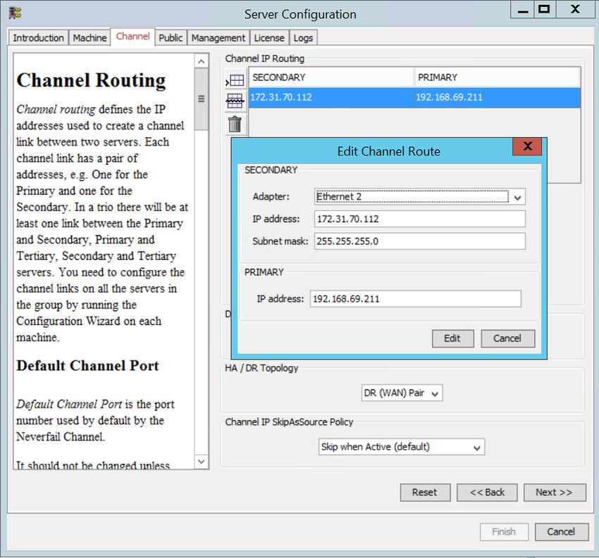
Neverfail Continuity Engine 2021 (v9.0)                                 Deploying to AWS Cloud Environment

    Notice
    Neverfail, LLC has taken all reasonable care to ensure the information in this document is accur‐
    ate at the date of publication. In relation to any information on third party products or services,
    Neverfail, LLC has relied on the best available information published by such parties. Neverfail,
    LLC is continually developing its products and services, therefore the functionality and technical
    specifications of Neverfail's products can change at any time. For the latest information on Nev‐
    erfail's products and services, please contact us by email ( info@neverfail.com ) or visit our Web
    site ( neverfail.com ).

    Neverfail is a registered trademark of Neverfail, LLC. All third party product names referred to in
    this document are acknowledged as the trade marks for their respective owner entities.

    Copyright (c) 2021 Neverfail, LLC. All rights reserved.

2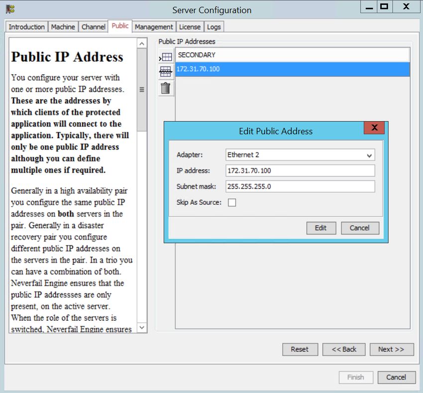
Neverfail Continuity Engine 2021 (v9.0)                         Deploying to AWS Cloud Environment

    Contents
    Deploying Neverfail Engine Cluster in Amazon Web Services Cloud Environment
    Deploying a Passive Node in an Amazon Web Services Cloud Environment

3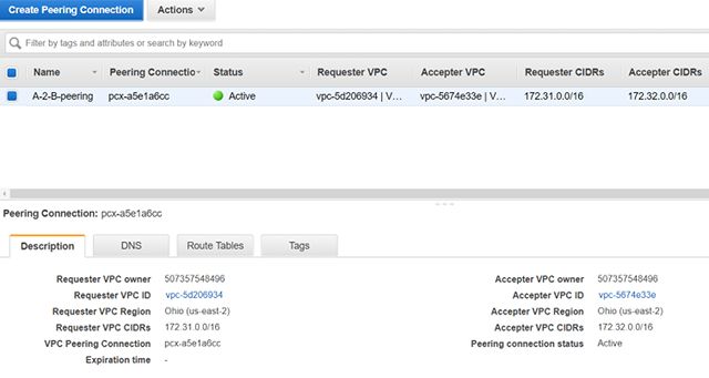
Neverfail Continuity Engine 2021 (v9.0)                                 Deploying to AWS Cloud Environment

    About This Book
    The Deploying to AWS Cloud Environment document provides information about Neverfail Con‐
    tinuity Engine deployment to Amazon Web Services Cloud Environment and the configuration
    required by the cloud infrastructure.

    Intended Audience

    This guide assumes a working knowledge of Amazon Web Services Cloud Environment.

    Using the Deploying to AWS Cloud Environment Guide

    This guide is designed to provide information related to Amazon Web Services Cloud Environ‐
    ment deployment of Neverfail Continuity Engine.

    Document Feedback

    Neverfail welcomes your suggestions for improving our documentation and invites you to send
    your feedback to docfeedback@neverfail.com .

    Abbreviations Used in Figures

    The figures in this book use the abbreviations listed in the table below.

     Abbreviation   Description

     Channel        Neverfail Channel

     EMS            Engine Management Service

     CE             Neverfail Continuity Engine

     NIC            Network Interface Card

     P2V            Physical to Virtual

     V2V            Virtual to Virtual

4
Neverfail Continuity Engine 2021 (v9.0)                                Deploying to AWS Cloud Environment

     Abbreviation    Description

     P2P             Physical to Physical

     SAN             Storage Area Network type datastore

    Technical Support and Education Resources

    The following sections describe the technical support resources available to you. To access the
    current version of this book and other books, go to https://www.neverfail.com/services-and-sup‐
    port/.

    Online and Telephone Support

    Use online support to view your product and contract information, and to submit technical sup‐
    port requests. Go to https://www.neverfail.com/services-and-support/.

    Support Offerings

    To find out how Neverfail Support offerings can help meet your business needs, go to https://
    www.neverfail.com/services-and-support/.

    Neverfail Professional Services

    Neverfail Professional Services courses offer extensive hands-on labs, case study examples,
    and course materials designed for use as on-the-job reference tools. Courses are available on
    site, in the classroom, and live online. For the day-to-day operations of Neverfail Continuity En‐
    gine, Neverfail Professional Services provides offerings to help you optimize and manage your
    Neverfail Engine servers. To access information about education classes, certification programs,
    and consulting services, go to https://www.neverfail.com/services-and-support/.

    Neverfail Continuity Engine Documentation Library

    The following documents are included in the Neverfail Continuity Engine documentation library:

     Document                 Purpose

     Installation Guide       Provides detailed setup information.

5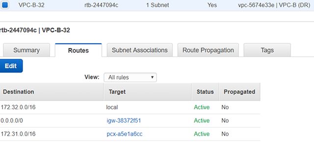
Neverfail Continuity Engine 2021 (v9.0)                                              Deploying to AWS Cloud Environment

     Document                   Purpose

     Using Neverfail EMS        Provides detailed usage instructions for Engine Management Service.

     Administrator's Guide      Provides detailed configuration and conceptual information.

     Deploying to AWS
                                Deploying Neverfail Engine in Amazon Web Services Cloud Environment.
     Cloud Environment

     SCOPE Data Collect‐
                                Neverfail SCOPE Data Collector Service Overview.
     or

                                Provides late-breaking information, known issues, and updates. The latest Release
     Release Notes
                                Notes can be found at https://www.neverfail.com/services-and-support/ .

    Conventions

    The documentation uses consistent conventions to help you identify items throughout the printed
    and online library.

     Convention                           Specifying

     Bold                                 Window items including buttons.

     Italics                              Book and CD titles, variable names, new terms, and field names.

     Fixed font                           File and directory names, commands and code examples, text typed by you.

     Straight brackets, as in
                                          Optional command parameters.
     [value]

     Curly braces, as in {value}          Required command parameters.

                                          Exclusive command parameters where only one of the options can be spe‐
     Logical OR, as in value1|value2
                                          cified.

6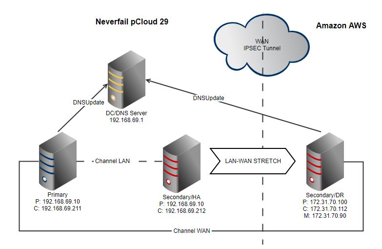
Neverfail Continuity Engine 2021 (v9.0)                                Deploying to AWS Cloud Environment

    Deploying Neverfail Engine Cluster in
    Amazon Web Services Cloud Environment
    This topic covers the scenario in which the Neverfail Engine Cluster is deployed in an Amazon
    Web Services (AWS) Cloud environment.

    Networking and Topology Prerequisites
    The deployment of Engine Cluster in an Amazon Web Services environment depends on the fol‐
    lowing topology variables:

        • Amazon Web Services Account - the same AWS account is recommended for deploying
          an Engine Cluster. Cross-account deployment is possible but not recommended.
        • Virtual Private Cloud (VPC)- the cluster deployment is possible on the same Virtual
          Private Cloud or on different Virtual Private Clouds.
        • Availability Zone (AZ) - the cluster deployment is possible on the same Availability Zone
          or on different Availability Zones.
        • AWS Region - the cluster deployment is possible on the same AWS Region or on different
          AWS Regions.

    Considering the mentioned scenarios (see above), different network topologies are available for
    the Engine Cluster deployment. However, as long as the Engine nodes are able to communic‐
    ate between themselves through a channel connection, the Engine Cluster will function cor‐
    rectly (considering the below mentioned Known Limitations).

    The only challange in deploying the Engine Cluster in an AWS environment is meeting the re‐
    quired interconnectivity conditions. Fortunately, the procedures for interconnecting different in‐
    stances, given the topology variables discussed above, are well documented by Amazon:

        • Inter AWS Region connection: Multiple Region Multi-VPC Connectivity
        • VPC-to-VPC peering:
              ◦ Creating and Accepting a VPC Peering Connection
              ◦ Updating Your Route Tables for a VPC Peering Connection
              ◦ Configurations with Routes to an Entire CIDR Block

7
Neverfail Continuity Engine 2021 (v9.0) Deploying to AWS Cloud Environment
• Cross region AMI copying (required for manual cloning of DR node to a different VPC):
Cross Region EC2 AMI Copy
Known limitations
1. Engine nodes should be deployed using the same AWS account.
2. Engine supported Public IP scheme
Depending on AWS EC2 cloud instances abstraction layer, you cannot have the same
Engine Public IP shared between two different AWS instances. This means that the
Engine traditional HA Pair or HA+DR Trio installs won't work in an all cluster AWS
cloud deployment. Hence, these are the supported scenarios for a AWS-to-AWS-(to-
AWS) topology. Please note that some of the scenarios require manual reconfiguration so
that the different public IPs condition is met.
◦ HA Pair with different Public IP addresses (requires post-install manual reconfigura‐
tion of different Public IPs - done from Configure Server Wizard on each node).
◦ DR Pair with different Public IPs on each node
Note: DR Pair with same Public IPs on each node installation requires
post-install manual reconfiguration of different Public IPs - done from
Configure Server Wizard on each node. The resulting configuration is
equivalent with the one above.
◦ HA+DR trio with different public IPs for the HA nodes AND DR node: (requires post-
install manual reconfiguration of different Public IPs - done from Configure Server
Wizard on each HA node).
3. Engine nodes cloning type
Supported cloning type: manual using the AWS cloning approach, i.e.
1. Go to the AWS instance
2. Select the instance and click on instance > action
3. Create image
4. Launch another instance from the image created above
8Neverfail Continuity Engine 2021 (v9.0) Deploying to AWS Cloud Environment
Installing Neverfail Engine DR Pair in different Amazon
Web Services VPCs
This use case example describes the procedure of deploying an Engine Cluster in a AWS-to-
AWS DR topology with Primary and Secondary nodes sitting in different VPCs, having the same
AWS Region and Availability Zone.
Note: - This procedure can be applied also to the other supported Engine Pair
scenarios - the only differences are the way the networking prerequisites between
Engine nodes are implemented and the eventual manual public IP post-install
configurations. - Trio HA+DR deployments require to manually clone the Second‐
ary node out of Primary then to add a DR Tertiary node by cloning it manually out
of Secondary. The cloning procedure is the same for both Secondary and Tertiary
nodes. - Static routes definition may be required on the Engine nodes defined in
different subnets in the same VPC. This depends on how the routing is defined
between the subnets at VPC level.
Step 1. Networking Prerequisites
• Existing AWS account with 2 VPCs defined in the same Region and Availability Zone as
described below.
• Primary-to-be server located in the Production VPC-A site.
VPC Configuration
• VPC-A (Production site)
◦ IPv4 CIDR: 172.31.0.0/16
◦ Subnet used by Production site: 172.31.71.0/24
• VPC-B (DR site)
◦ IPv4 CIDR: 172.32.0.0/16
◦ Subnet used by Production site: 172.32.73.0/24
• VPC-A to VPC-B Peering connection defined: Configurations with Routes to an Entire
CIDR Block
9Neverfail Continuity Engine 2021 (v9.0) Deploying to AWS Cloud Environment
• Routing table updated with correct peering and subnet association
• Each VPC Security Group updated with a inbound rule for allowing the traffic from the re‐
mote/peered subnet source, i.e.
◦ Allow traffic from 172.32.73.0/24 source for VPC-A SG
◦ Allow traffic from 172.31.71.0/24 source for VPC-B SG
10Neverfail Continuity Engine 2021 (v9.0) Deploying to AWS Cloud Environment
Important: In all the next steps, you must assign to each EC2 instance (EMS,
Primary, Secondary) ALL the private IP addresses that will be used on that given
box, i.e. public IP-to-be, Channel IPs, Management IP (if exists).
Step 2. Installing the Engine Management Service (EMS)
The EMS can be installed on any supported workstation or server which can access VPC-A and
VPC-B subnets. The EMS installation procedure is described in the Installation Guide docu‐
ment.
Step 3. Installing Engine on Primary Server located in VPC-A (production site)
• Using the EMS, install Engine on the Primary server as indicated in the Installation Guide.
• Make sure all the Public, Channel and Management IPs defined and managed by Engine
are registered/configured on the AWS EC2 Primary instance. For example:
◦ Public IP: 172.31.71.101/24
◦ Channel IP: 172.31.71.111/24
Step 4. Adding Secondary/DR Node located in VPC-B (DR site)
• Using the EMS, add a Secondary DR node as indicated in the Installation Guide.
◦ Configure Secondary with the correct Public and Channel IP addresses:
▪ Public IP: 172.32.73.102/24
▪ Channel IP: 172.32.73.112/24
Configure also the correct GW and DNS server corresponding to the DR VPC-B site.
◦ Choose the Assisted cloning type then when requested
11Neverfail Continuity Engine 2021 (v9.0) Deploying to AWS Cloud Environment
◦ Wait until EMS informs you that the Secondary Server is ready to be manually
cloned, then proceed with the AWS cloning as indicated above.
◦ Go to the AWS Primary instance.
◦ Select the instance and click on Instance > Action > Create image.
◦ Launch AWS Secondary instance from the Primary AMI image created above.
◦ Make sure the Secondary instance type matches (at least) the CPU, memory, stor‐
age, and networking capacity configured for Primary instance.
◦ Configure the instance with ALL the IPs that will be used on the Secondary server
(Public, Channel, Management IPs).
◦ Configure the VPC-B corresponding Security Group.
◦ When Secondary instance is created it will connect automatically to the Primary.
Step 5. Post-installation and other deployment considerations
• Trio: for HA+DR trio deployment, repeat the Step 4 above, having as source the Second‐
ary Server. Make sure the Tertiary instance is configured accordingly with the type, IP ad‐
dresses, security group, etc.
• Configuring Static Routes for Channel traffic: If these are required then configure them
as indicated in the How to Stretch LAN to WAN in Neverfail IT Continuity Engine in a
Primary - Secondary Configuration Knowledge Base article (also in the following chapter).
• Switchover considerations: EMS Server should access both Primary and DR subnets.
Otherwise, when Secondary is active it cannot connect to the newly active.
12Neverfail Continuity Engine 2021 (v9.0) Deploying to AWS Cloud Environment
Deploying a Passive Node in an Amazon
Web Services Cloud Environment
This topic covers the scenario in which the Secondary (or Tertiary, if applicable) cluster node,
part of an on-premise Neverfail Engine Cluster, is moved into an Amazon Web Services (AWS)
Cloud environment.
The procedure required to accomplish the described task is called stretching (LAN to WAN
stretching) can be summed up as follows:
1. The Secondary Engine node must be prepared for movement.
2. The AWS Cloud environment must be configured to run the Secondary node.
3. The Secondary node must be imported in the AWS Cloud environment.
4. The Neverfail Engine must be configured on the moved Secondary and on the on-premise
Primary.
Detailed Scenario
Initial state: the Engine cluster is hosted on-premise and has a Primary and a Secondary HA
node. The DNS server is also hosted on-premise, in the same network environment. The two
cluster nodes and the DNS server communicate through a local area network (LAN).
Example IP initial configuration:
IP Value
Public and Channel subnet 192.168.69.x/24
Public IP 192.168.69.10
Primary Channel IP 192.168.69.211
Secondary Channel IP 192.168.69.212
DNS server IP 192.168.69.1
13Neverfail Continuity Engine 2021 (v9.0) Deploying to AWS Cloud Environment
Target state: the Engine cluster is stretched (LAN - WAN stretching) so the Primary node and
the DNS server reside in the same on-premise, LAN environment, while the Secondary node
resides in the AWS Cloud environment. The AWS hosted Secondary is now serving as a DR
node in the Engine cluster and is communicating with the Primary node and DNS server via
WAN.
Example IP target configuration:
IP Value
Primary Public and Channel subnet 192.168.69.x/24
Primary Public IP 192.168.69.10
Primary Channel IP 192.168.69.211
DNS server IP 172.31.70.x/24
Secondary Public and Channel subnet 172.31.70.x/24
Secondary Public IP 172.31.70.100
The following diagram illustrates this scenario:
14Neverfail Continuity Engine 2021 (v9.0) Deploying to AWS Cloud Environment
Performing the Stretching Procedure
The stretching procedure implies the steps described below.
1. Creating the IPSec tunnel.
The tunnel is required for establishing a connection and allowing traffic between the on-
premise Engine host and the AWS Cloud.
2. Preparing the Secondary node for stretching.
Note: The scenario implies that the Primary node is active and replicating
on the Secondary passive node.
The Secondary cluster node must be prepared before moving it to AWS Cloud. Make sure
to follow the steps below:
◦ Add the Domain Admin account to Neverfail Engine:
1. Login to the Neverfail Advanced Client.
2. Click Application.
3. Open the Tasks tab and highlight Neverfail Engine.
4. Click User Accounts..., click Add, and enter the Domain Admin account de‐
tails.
5. Click OK and click Close.
◦ Shutdown Engine on all nodes.
◦ On the Secondary node, set the Engine service startup to manual.
◦ On the Secondary node, configure the UTC time settings as required by AWS.
◦ On the Secondary node, set the IPv4 to DHCP. The IPv6 protocol should be dis‐
abled.
◦ On the Secondary node, remove all removable drives (including CD and Floppy) and
network drives.
◦ Shut down the Secondary node.
◦ Export the Secondary node as OVA.
3. Setting up AWS Cloud.
Follow the AWS setup procedures detailed here to set up your AWS Cloud: Setting Up with
Amazon EC2.
15Neverfail Continuity Engine 2021 (v9.0) Deploying to AWS Cloud Environment
4. Importing the Secondary OVA to AWS.
The detailed procedure is described here: Importing a VM as an Image Using VM Import/
Export. The essential steps are listed below:
◦ Create an Amazon S3 Bucket, required for uploading OVA images to AWS (prior to
importing). Check out the procedure here: How Do I Create an S3 Bucket?.
◦ Upload the Secondary OVA to the AWS S3 bucket.
◦ Create a new IAM user. This user will be used to import the virtual machine to AWS
using the AWS CLI. While being logged with the root account in AWS console, go to
Services > Users and select Add User. Note down the Access key ID and Secret
key (they are required for CLI connections to AWS).
Note: Make sure to add sufficient permissions to the new AWS user.
◦ Install the AWS Command Line Interface, required by the VM Import Service Role.
Check out this link for more information: Install the AWS Command Line Interface on
Microsoft Windows.
◦ Create the VM import Service role. Check out this document for more information:
Importing a VM as an Image Using VM Import/Export.
After being created, the vmimport role should be available under IAM > Roles.
▪ Edit the role-policy.jsonfile. Use the file bucket ARN where indicated as
disk-image-file-bucket. The file bucket ARN is displayed when hovering and
clicking the S3 bucket row.
▪ Attach the policy to the role created above as indicated in AWS import role pro‐
cedure.
▪ Import the Secondary OVA to AWS AMI (considering that the upload is
complete): Edit the containers.json file inserting the appropriate S3 bucket
name and OVA file name (as displayed in the bucket) then import the OVA
to AMI using the AWS CLI (as instructed in the AWS procedure). Check
periodically for import task status, as instructed.
Note: The ImportTaskId will be used to check the status of the import
operation.
16Neverfail Continuity Engine 2021 (v9.0) Deploying to AWS Cloud Environment
5. Configuring and launching the EC2 Instance.
◦ Go to AWS > EC2 > AMIs and select the image imported at previous step.
◦ Click Launch and continue with instance configuration prior of launching.
◦ Choose the instance type which should match your Primary's resources.
◦ Configure the instance details.
Important: Choose the subnet configured for IPSec tunneling between
the on-premise host and AWS. Also, enable the public IP auto assigna‐
tion in order to be able to access (RDP) the AWS-hosted Secondary
instance from a remote host (from a different subnet).
◦ Configure the desired storage size.
◦ Configure the Security group to allow traffic between the on-premise and the AWS
subnets. Here you can also configure the access for RDP connections from other
management computers.
◦ Create a new key or use an existing one then connect to the new instance.
◦ When the instance status is running, you can access (RDP) the AWS-hosted Sec‐
ondary.
6. Reconfigure the Engine cluster as an on-premise-to-AWS DR pair.
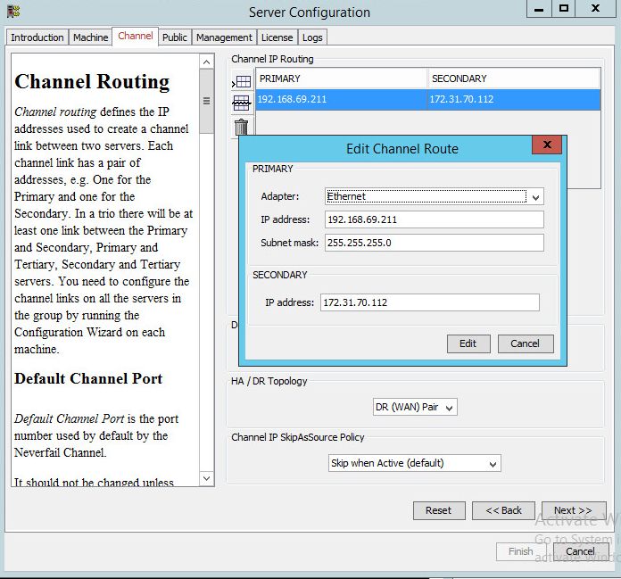
◦ Configuring the migrated Secondary node.
▪ Launch Configure Server Wizard and Configure the new Secondary Channel
IP. Make sure that an existing NIC adapter is selected.
▪ Set the HA/DR Topology to DR (WAN) Pair.
17Neverfail Continuity Engine 2021 (v9.0) Deploying to AWS Cloud Environment
▪ Configure the new Secondary Public IP. Make sure that an existing NIC ad‐
apter is selected.
▪ Set the Engine service startup to Automatic.
▪ Important: On AWS console, select Instance > Actions > Networking > Man‐
age IP addresses and assign to your EC2 instance ALL the private IP ad‐
18Neverfail Continuity Engine 2021 (v9.0) Deploying to AWS Cloud Environment
dresses that will be used on Secondary, i.e. public IP address Channel IP ad‐
dress, Management IP address (if exists). This will allow traffic between the
mentioned IP addresses and remote on-premises site.
◦ Configuring the Primary node.
▪ Launch the Configure Server Wizard and set the new Secondary Channel IP.
▪ Set the HA/DR Topology to DR (WAN) Pair.
▪ Start the Engine on both Primary and Secondary nodes.
◦ Configuring DNSUpdate task.
On the Primary Server, connect to Advanced Management Client and add two Net‐
work Configuration tasks, as follows:
▪ For the Primary server, select Primary radio button.
▪ Edit command DNSUpdate -auto.
▪ Click Run Asand select from the menu the Domain Account previously con‐
figured in the User Accounts dialog.
▪ For the Secondary server, select Secondary radio button.
▪ Edit command DNSUpdate -auto.
19Neverfail Continuity Engine 2021 (v9.0) Deploying to AWS Cloud Environment
▪ Click on Run As and select the Domain Account previously configured in the
User Accounts dialog.
◦ Configuring static routes for channel traffic.
If static routes are required (for multi-NIC install), configure them as indicated here:
▪ Open Routing and Remote Access from Administrative Tools.
▪ Select the server name, then from the Action menu select Configure and En‐
able Routing and Remote Access to launch the configuration wizard.
▪ Select Custom Configuration > LAN routing and verify that the RRAS ser‐
vice is started.
▪ Select the server again, navigate to IP Routing and select Static Routes.
▪ From the Action menu select New Static Route.
▪ From the drop-down, select the channel interface and enter the destination
channel IP followed by the mask 255.255.255.255 and the source machine
gateway.
▪ Test the channel routing using the following command to ensure that all the
packets will be sent using the channel IP and not the principal (public) IP.
pathping -n Channel\_IP
Note: For a trouble free WAN implementation, it is recommended
that you use RRAS for implementing static routes. Avoid using
the interface ID when creating static routes using the "route"
command because the interface ID is dynamic and increments
each time a server is restarted or a NIC is disabled/enabled, and
this change will make the route invalid.
Note: The persistent routes ensure that any communication with the
channel network is in fact established via the physical channel NICs.
◦ Configuring DR ping targets.
On the Primary server update the Server Monitoring ping routing configuration:
▪ In the Neverfail Advanced Client, select Server Monitoring.
▪ On the Server Monitoring screen, in the Configure Pings section, click Config‐
ure....
20Neverfail Continuity Engine 2021 (v9.0) Deploying to AWS Cloud Environment
▪ Browse to the Ping Routing tab of the new window.
▪ Update the Primary and Secondary IP addresses to match the new IP scheme
implemented in the steps above. Update both the Ping From and Ping To fields.
◦ Configuring VMware Tools service protection.
Issue: Considering initial HA pair was a VMware V2V, the VMware Tools service is
installed and protected by the vSphere Integration plugin. The service is also present
on the stretched AWS instance, though it cannot be started in this new context. Thus.
if a switchover is attempted, the service will be attempted to be started on the S/A but,
as expected, will fail (application errors will be logged).
WORKAROUND (use one of the following):
▪ uninstall vSphere Integration plugin if this is not used anymore when Primary is
active
▪ modify target states for the VMware Tools service to be Any/Any: This can be
done by Adding the service to User Defined protection while Primary is active
◦ Switchover considerations.
The Engine Management Server should access both Primary and DR subnets. Oth‐
erwise, when Secondary is active it cannot connect to the newly active.
21You can also read