Design and Performance of Modern Storage Ring Light Sources - Robert Hettel, SLAC
←
→
Page content transcription
If your browser does not render page correctly, please read the page content below
Design and Performance of Modern
 Storage Ring Light Sources

 Robert Hettel, SLAC
Light source brightness

 FEL and storage ring light sources are complementary
 FELs: high peak brightness, strongly perturbs sample under study
 Storage rings: low peak brightness, minimal sample perturbation, high rep
 rate/stability, many simultaneous users, ….
Outline

• Introduction
• Diffraction limited emittance, brightness and coherence
• Properties of 4th generation storage ring (4GSR) light
 sources and science applications
• 4GSR lattice implementations
• 4GSR challenges and solutions
• Future of DLSRs
• Appendices
 • 4GSR R&D Topics
 • 4GSR Accelerator and Science Reference
 • Low Emittance Ring and 4GSR Workshops

Acknowledgments

Many appreciated contributions from:
 D. Robin and C. Steier, ALS
 M. Borland, L. Emery, APS
 R. Bartolini, Diamond
 P. Raimondi, ESRF
 M. Eriksson, S. Leemann, MAX-IV
 L. Liu, Sirius
 A. Streun, SLS
 L. Nadolski, Soleil
 H. Ohkuma, K. Soutome, H. Tanaka, SPring-8
 Y. Cai, T. Rabedeau, Z. Huang
 SLAC and SPEAR3 Beam Physics Groups
 SLAC Directors, I. Lindau, C. Pellegrini, J. Stohr, H. Winick
 and participants in FLS, LowERing and DLSR workshops
4GSR (DLSR) Reference

Journal of Synchrotron Radiation (2014).21

• 8 articles on accelerator physics and technology

• 2 articles on MBA rings in construction (MAX-IV and SIrius)

• 10 articles on scientific applications

• 4 articles on X-ray beam line technology (optics,
 instrumentation, detectors, etc.)

 See Appendix 2
Light source design topics
Light source design topics – cont.
SESAME (Jordan)

 Environmental science &
 Physics Laboratory
 Archaeology Laboratory

 Energy; 2.5 GeV
 Circumference; 133m
 Emittance; 26 nm-rad
 BessyI 12 Insertion Devices
 0.8 GeV
 injector
 13 Bend Magnet beam
 lines
 Maximum beam line
 length; 37m
 Space for future full
 energy injector in main
 ring tunnel
 Cheap
 Bio-Medical Materials science
 Laboratory Laboratory
Sirius (Brazil)

 Energy; 3 GeV
 Circumference; 518 m
 Emittance; 0.2 nm-rad

 Up to 18 IDs
 Up to 18 BM beam lines
 Maximum beam line
 length: 150 m
 ~505 M USD
What is needed to design, build and operate a light source

Definition of the science mission for the facility
 • areas of research
 Must be very clearly articulated in the
 • industrial partners user community and funding agencies
 • education goals
 • etc.
Specification of photon parameters
 • spectral range
 • spectral brightness and flux
 • beam size requirements
 • photons/pulse
 • pulse length
 • etc.
What is needed - cont.

Specification of beam line and source requirements
 • beam line applications
 • number of IDs and bend magnet lines
 • ID types and lengths
 • beam line optics and lengths
 • etc.
Specification of accelerator parameters
 • electron energy, emittance, current, bunch length
 • ring circumference, number and length of straight sections
 • lattice design and accelerator physics studies
 • injector and injection
 • etc.
What is needed - cont.

Accelerator engineering design
 • mechanical, vacuum, low and high power electrical (DC and pulsed power,
 etc), high and low power RF, electronics and instrumentation, computer
 control system, feedback systems process control, safety systems, etc.
Beam line engineering design
 • X-ray optics, precision motion control, detectors, computer controls, etc.
Radiation physics and safety
 • beam loss and radiation studies
 • shielding design
 • specification of radiation safety system requirements
Facility engineering design
 • stable floor, building, water, air conditioning, electrical utilities, water cooling,
 gas and LN infrastructure, etc.
Project management and business services
 • Extremely important!
The world is moving to ever brighter ring sources 2-‐bend achromat 7-‐ bend achromat 5-‐ bend achromat NSLS-‐II MAX-‐IV SIRIUS BNL: NSLS-‐II (2014): 3 GeV, Sweden: MAX-‐4 (2016): 3 GeV, Brazil: SIRIUS (2016/17): 3 GeV,
Brightness and coherence of present rings

 Best-available brightness
 and coherent fraction for
 selected presently-operating
 rings, with operating parameters
 and insertion devices.

 Parameters provided by facility
 contacts.
 Compiled by M. Borland for
 BESAC Sub-Committee
 meeting, July 2013.
Brightness and coherence of near-future rings

 Selected rings/upgrades
 now under construction,
 with anticipated parameters
 and insertion devices

 Parameters provided by facility
 contacts.
 Compiled by M. Borland for
 BESAC Sub-Committee
 meeting, July 2013.
Brightness and coherence of planned rings

 Selected upgrades now being
 planned (except APS-II), with
 anticipated parameters and
 ESRF-specified insertion
 devices.

 Parameters provided by facility
 contacts.
 Compiled by M. Borland for
 BESAC Sub-Committee
 meeting, July 2013.

 Notes:
 1. ESRF-II: 6 GeV, 200mA, 150 pm
 2. SPring-8-II: 6 GeV, 300 mA, 67pm
Brightness and coherence of future rings

 Selected diffraction-limited
 rings now being designed,
 with identical Nb3Sn super-
 conducting insertion devices
 and some PM devices.

 Parameters provided by facility
 contacts.
 Compiled by M. Borland for
 BESAC Sub-Committee
 meeting, July 2013.
 Notes:
 1. 0.2km/2GeV: ALS-II, 52 pm
 2. 1.1km/6GeV: APS-II, 80 pm
 3. 1.4km/6GeV: SP8-II, 2nd stage, 34 pm
 4. 2.2km/6GeV: PEP-X, 5 pm
 5. 6.2km/9GeV: tauUSR, 3 pm
 6. Except for 0.2km ring, uniform selection
 of SCUs and APS HPMs used.
Spectral brightness and coherence Spectral brightness: photon density in 6D phase space N ph (λ) Bavg (λ) ∝ (ε x (e−) ⊕ ε r (λ))(ε y (e−) ⊕ ε r (λ))(s ⋅ % BW) N ph (λ) B pk (λ) ∝ (ε x (e−) ⊕ ε r (λ))(ε y (e−) ⊕ ε r (λ))(σ t ⋅ % BW) Coherent fraction: ε r (λ ) ε r (λ ) f coh (λ) = ⋅ (ε x (e−) ⊕ ε r (λ)) (ε y (e−) ⊕ ε r (λ)) Coherent flux: 2 ⎛ λ ⎞ Fcoh (λ) = f coh (λ) ⋅ F(λ) = B avg (λ) ⋅ ⎜ ⎟ ⎝ 2 ⎠
Diffraction-limited emittance εr(λ) K-J Kim in Characteristics of Undulator Radiation, AIP 1989 Coherent beam of wavelength λ focused to spot size Δx will diffract with angle Δψ = ~λ/Δx In transversely coherent beam, spatial distribution Ek(x,z) for wavenumber k is related to angular distribution ℇk( , ) by Fourier transform (for 1-D in x): ℇ↓ ( , )=1/√2 ∫↑▒ ↓ ( , ) ↑ ↓ ( , )=1/√2 ∫↑▒ℇ↓ ( , ) − ↑ ≪1 ⇒ ↓ ↑ ( ) ↓ ( )= /4 = ↓ ( ) Diffraction limited emittance for coherent Gaussian photon distribution
Diffraction-limited emittance – cont. Fitting Gaussian profiles to spatial and angular profiles for undulator radiation at λ: P. Elleaume, in Wigglers, Undulators, and Their Applications, 2003. ↓ ↑ ( )≈1.9√2 /4 ↓ ↑ ( )≈√ /2 ⇒ ↓ ↑ ( ) ↓ ↑ ( )≈ /2 = ↓ ( ) Diffraction limited emittance for undulator radiation from single electron filament Other similar estimates for εr(λ): W. Joho, SLS Note 4/95; O. Chubar, FLS2012
Diffraction-limited emittance – cont.

 “Ultimate storage rings
X-ray emittance from electron source Transverse emittance Σx,y (λ) of X-ray beam from undulator (length L) is convolution of photon emittance εr from e- filament and e- emittance εx,y(e-) (Gaussian beams): ↓ ( )⊕ ↓ , ( −)=√ ↓ ↑2 ( )+ ↓ , ↑2 ( −) √ ↑′ ↓ ↑2 ( )+ ↑′ ↓ , ↑2 ( − ↓ ↑ ( )≈√2 /2 Here ′↓ ↑ ( )= ↓ ↑ ( )≈√ /2 ↓ , ↑ ( −)=√ ↓ , ↓ , +( ↓ , ′↓ , ↑ ( −)=√ ↓ , / ↓ , +( ′↓ , )↑2 (η, η’ =0 for )↑2 achromat) Transverse emittance Σx,y minimized when εx,y is minimized and photon and e- phase space orientations are matched: Note: many ↓ ↑ ( )/ ′↓ ↑ ( ) = ↓ , ↑ ( −)/ ↑′authors ↓ , ↑ ( cite −) ⇒ ↓ , ↑ = / ↓ , ↑ = / 2
Coherent fraction

 Coherent flux is
 important too: a
 low coherent
 fraction and high
 flux can yield the
 same coherent
 flux as a high
 coherent fraction
 and low flux

 Optimize trade-
 off between low
 of emittance vs.
 stored current

 • Many rings operate now with εy 2πεx,y(e-)
Storage ring emittance landscape

 CLS
 MAX-II PLSSPEAR3
 SPEAR3
 10
 CANDLE
 SAGA-LS ALS ELETTRA
 SLS ASP
 BESSY-II ALBA ESRF
 SSRF SPring8
 SOLEIL APS
 Diamond
 Emittance (nm)

 TPS

 PETRA-III
 1 SPEAR3 QBA
 •
 NSLS-II

 SIRIUS

 MAX-IV ESRF-II
 Planned
  light
  source
 0.1
 • Existing
  light
  source
 APS-U
 •

 PEP-X

 0.01
 0 1 2 3 4 5 6 7 8 9
 PEP-X
 Energy (GeV) • 24
Properties of 4GSRs
• Brightness and coherence are as high as possible for given beam current
• Small horizontal and vertical beam
 dimensions and the possibility of “round”
 beams – good for X-ray optics, minimal
 need for aperturing
• Short bunches courtesy of C. Steier

 ~5-10 ps RMS from low momentum compaction factor – bunch lengthening
 usually needed to combat emittance growth from IBS and improve lifetime;
 synchrotron frequency < 1 kHz for large rings
• “Long” lifetime:
 Touschek lifetime increases with small
 bunch dimensions Touschek lifetime for NSLS II
 assuming emittance can be
• Large circumference for multi-GeV rings (km) arbitrarily reduced (M. Borland,
• Damping wigglers used in some cases to lattice courtesy W. Guo)

 combat IBS and reduce emittance by ~x2-3
• Small dynamic aperture (~mm) for aggressive lattices (⇒ on-axis “swap-
 out” (A. Xiao et al. NA-PAC13) or possibly longitudinal injection (M. Aiba et al.,
 IPAC14))
4GSR properties – coherence

Transversely coherent x-rays
- Uniform phase wavefronts: coherent imaging, holography, speckle, etc.
- Focusable to smallest spot size: nano-focus
- High flux (~1014-1015 photons/sec) in small spot: slits may not be required, etc.
- Round beams: H-V symmetric optics, circular zone plates, flexibility in optics

Some issues with coherence:
- Reduced depth of focus – a problem for some forms of imaging
- Speckle from coherent beams a problem for some applications
- These problems can be resolved by “spoiling” beam on beamline
Fundamental challenge: science case (in the US) XDL 2011 Workshops for ERLs and DLSRs (Cornell, June 2011) : § Diffraction Microscopy, Holography and Ptychography using Coherent Beams § Biomolecular Structure from Nnanocrystals and Diffuse Scattering § Ultra-fast Science with “Tickle and Probe” § High-pressure Science at the Edge of Feasibility § Materials Science with Coherent Nanobeams at the Edge of Feasibility § Frontier Science with X-ray Correlation Spectroscopies using Continuous Sources (time resolution ∝ B2) BESAC Subcommittee on Future Light Sources (July 10-12, 2013) A consensus report on future opportunities from scientists at ALS, APS, NSLS-II, SSRL, together with a broad community of scientists at laboratories and universities. Applications address “Grand Challenge Science”
Low emittance lattice design

Horizontal (natural) emittance determined by balance between
radiation damping and quantum excitation due to synchrotron
radiation in all magnets:

How to minimize emittance?
 • Reduce dispersion and beta function in bend magnets (wigglers/undulators)
 • Achieved by refocusing beam ‘inside’ bending magnets -> need space
 • ‘Split’ bending magnets -> multi bend achromats

 28
The path to low emittance rings Emittance scaling with energy and circumference: ↓0 = ( , ) ↑2 /( ↓ ↑ ↓ ↑ )↑3 ∝ ↑2 / ↑3 for fixed cell type ↓ =1/1+ ↓0 ↓ = /1+ ↓0 Ns = # sectors in ring, Nd = # dipoles/sector Emittance reduction with damping wigglers: εw 1+ f 1 = ≈ U0 = energy loss/turn in dipoles εo Lw ⎛ ρ o ⎞ 2 Uw 1+ 1+ UW = energy loss/turn in wigglers ⎜ ⎟ 4π ρo ⎝ ρ w ⎠ Uo Emittance reduction with damping partition: H Gradient dipoles 2 H(s)/⇢(s)3 ds ✏x = Cq H Robinson wigglers Jx 1/⇢(s)2 ds Amplitude bumps in quads Damping partition
Common lattice options
 Achromat Symmetry Point Achromat Symmetry Point

 Dispersion Function Dispersion Function

1/2 Insertion Straight 1/2 Insertion Straight 1/2 Insertion Straight 1/2 Insertion Straight

 Achromat Achromat
 Insertion Symmetry Point Insertion Symmetry Point

 Achromat Symmetry Point • Early 3rd generation SR sources all used
 double/triple bend achromats (some with
 gradient dipoles)
 • Later optimization included detuning from
 Dispersion Function
 achromatic condition (Optimizing effective
1/2 Insertion Straight 1/2 Insertion Straight emittance)
 • New designs (including DLSRs) employ MBA
 • Damping wigglers can help (emittance,
 Achromat
 Insertion Symmetry Point damping time, IBS) but trade energy spread
 30
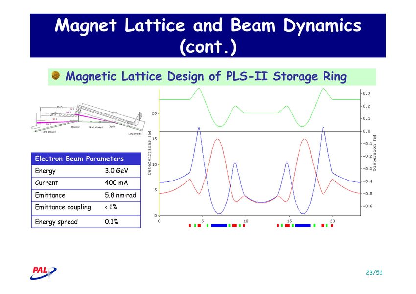
Other ring implementations

“Double DBA” for PLS-II
• Compact lattice that
 doubled the number of
 straight sections for PLS
• Effective emittance in
 straight sections is larger
 due to dispersion η
History of TME / MBA

Work in 1990 to find theoretical minimum emittance structures – Einfeld, et al. (NIM 1993,
PAC 1995, EPAC 1996)
MBA is a modification of this, with (detuned) TME structure in the middle of the arc and
(short) matching sections at ends
Originally considered challenging (“chromaticity wall”)
Max-4 is first full implementation of MBA
 32
The multibend achromat optimization cycle
 A. Streun, PSI
Example MBA Lattices

Max-4 – 7BA, octupoles,
 ESRF-2- HMBA, APS-U - HMBA, swap-out,
M. Eriksson
 P. Raimondi M. Borland

 ALS-U – 9BA, octupoles,
PEP-X – 7BA, 4th order achromat, Y. Cai swap-out, H. Tarawneh, C. Steier
 34
ESRF lattice conversion - hybrid MBA

 Present 2BA εx/y = 147/5 pm.rad @ 6 GeV, 200 mA
 εx = 4 nm.rad
 17 magnets
 Space between D1-D2 and D6-D7:
 β-functions and dispersion allowed to
 grow to enable chromaticity correction
 with efficient sextupoles
 Dipoles D1, D2, D6, D7:
 Bleu: Dipoles Red: Quadrupoles Green: sextupoles
 longitudinally varying field to further
 Proposed Hybrid 7BA
 reduce emittance
 εx = 150 pm.rad
 29 magnets Central section:
 combined dipole-quadrupoles D3-4-5;
 high-gradient focusing quadrupoles
 Source points for BM beamlines
 have same fields, positions, angles

 D1 D2 D6 D7
 D3 D4 D5
 Courtesy P. Raimondi, ESRF.
ESRF lattice conversion – cont.

 High gradient quadrupoles
 85 T/m Quadrupole
 Around 50 T/m

 D7
•Spec:100 T/m x 335 mm D6
•Bore radius: 11 mm
•Mechanical length: 360 mm
 D2 D5
•1 kW
 D3 D4
 D1

 Combined dipole quadrupoles Sextupoles
 0.85 T / 45 T/m & 0.34 T / 50 T/m 1700 T/m-2

Permanent magnet dipoles
longitudinal gradient 0.16 - 0.6 T,
magnetic gap 22 mm
2 metre long, 5 modules
With a small tuning coil 1%
 Courtesy P. Raimondi, ESRF.
APS-U lattice conversion - hybrid MBA

 εx/y = 65/8 pm.rad @ 6 GeV, 200 mA
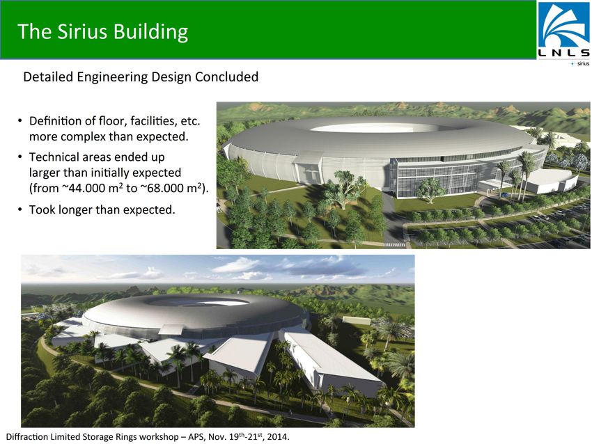
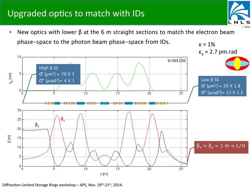
Sirius 5BA εx/y = 190-270/3 pm.rad @ 3 GeV, 350 mA

 38
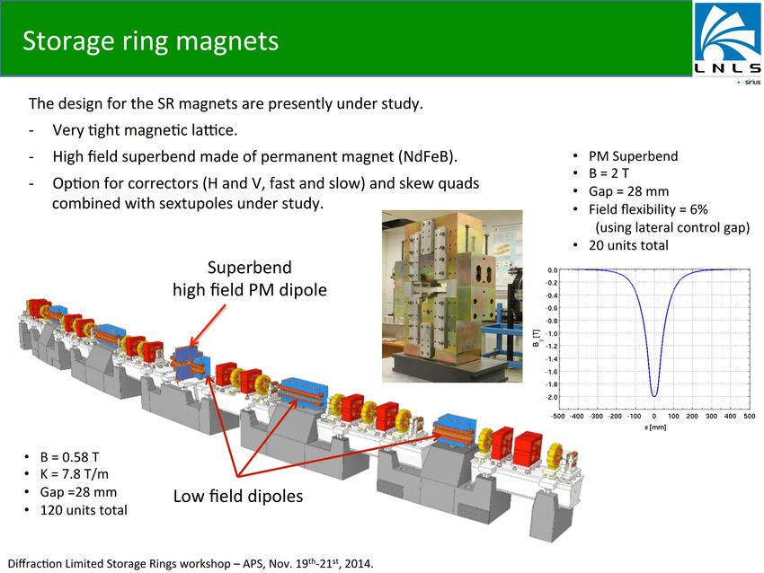
ALS-U 9BA εx/y = 50/50 pm.rad @ 2 GeV, 500 mA

 superbend option

 includes octupoles
Longitudinal gradient dipoles

 βx βy η

 longitudinal
 gradient anti-bend
 bend

 ESRF-2 APS-U A. Streun
• Allow reduction in emittance and larger dispersion in
 chromatic correction section
• Potential draw backs:
 • Non-trivial to build
 • Longer
 • Highest field in line with straights (for HMBA)
 40
Longitudinal dipoles and anti-bends

 dispersion: A. Streun, SLS
 anti-bend
 off / on

 βx βy

relaxed TME cell, 5°, 2.4 GeV, Jx ≈ 2
Emittance: 500 pm / 200 pm
 • Very new proposal
 • Allows more control over momentum compaction factor as
 well as separate control of beta-function and dispersion
 41
Damping wigglers NSLS-2 εw 1+ f 1 = ≈ εo Lw ⎛ ρ o ⎞ 2 U 1+ 1+ w X. Huang, PEP-X ⎜ ⎟ Uo 4π ρo ⎝ ρ w ⎠ • Help to reduce the equilibrium emittance – without reducing momentum compaction factor • Also decrease damping time (beneficial for IBS) • Possible tool to control vertical emittance (vertical wiggler, vertical dispersion) • Increase energy spread (reduces higher undulator harmonics) • Can impact dynamic aperture • Occupy space, increase RF need, need to handle high power synchrotron light 42
3PW, Superbends, …

 L. Liu,
 SIRIUS

 ESRF-II

MBA lattices might have weak field dipoles ALS-U
3PW or Superbends allow to extend spectrum to harder photon energies
Can also help to reduce the emittance (longitudinal gradient dipole) – if done right
Need to create space in lattice, correct for potential symmetry distortion

 43
Future large DLSRs?

BAPS (China - Beijing)
 5 GeV, 1-1.5 km,
BAPS

IHEP/Beijing:
Other methods of emittance control
If ring is diffraction limited in horizontal plane, vertical
emittance does not need to be smaller
 • Very different from current rings which run with emittance ratios
 between 0.1% - few %
 • Intrabeam scattering and Touschek lifetime require the vertical
 emittance to not be too small
User experiments sometimes prefer round beams
Control of vertical emittance is needed
 • Coupling control (reduces horizontal emittance, fine with swap-out,
 but challenging with asymmetric apertures for off-axis injection, limits
 tune choices)
 • Vertical Dispersion (local/global) – routinely used in light sources
 right now, but only up to maybe 10% emittance ratio
 • Damping Wigglers (spurious or intrinsic vertical dispersion)
 • Moebius ring / emittance exchange / … 46
Scaling
 M. Borland

• However, more and more magnet require magnets
 to become stronger (quadupoles about quadratically,
 sextupoles even quicker)
 – Engineering limits
 – Nonlinear dynamics
• Energy scaling is complex (magnet strength, C)
 47
Scaling – cont. ALS APS-U ∝ ↑2 / ↑3 • Slope of optimized parameter sets indicates R. Bartolini that this merit function is too simple 48
Scaling – cont. A USR-type Ring Design Study, X. Huang, SSRL, 8/30/2012 4GSR design involves packing as many TME cells as possible into a fixed circumference to reduce emittance. Quadrupole and sextupole strengths increase to keep proper cell phase advance. For linear optics, cell length L scaling: √ ↓1 =√ ↓1 / ∝ For circumference C, number of cells N related to cell length by NL = C For a given quadrupole gradient limit, beam energy E: ∝ ↑2 / ↑3 ∝ ↑7/2 / ↑3 ↓1 ↓↑3/2 from 2012 (dated)
Scaling – cont. energy circumference emittance gradient B1 Form factor [GeV] [m] [nm] T/m NSLS-II 3 780 2 20 1.815 Diamond 3 561.6 2.7 20 0.915 Normalized form SLS 2.4 288 5.5 22 0.633 factor: Soleil 2.75 354.1 3.74 21 0.463 ↓1 ↓↑3/2 ↑3 / SSRF 3.4 432 3.9 21 0.418 TPS 3 518.4 1.7 18 0.387 APS 7 1104 2.5 19 0.307 PLS-II 3 281.8 5.8 22 0.286 SPEAR3 3 234 9.8 22 0.277 MAX-IV 3 528 0.24 43 0.213 SIRIUS 3 518 0.28 40 0.211 ALBA 3 266 4.5 23 0.200 ALS 1.9 196.8 2 22 0.166 spring8-II 6 1435.95 0.067 56 0.157 ESRF upgrade 6 844.4 0.15 85 0.134 APS-U 6 1104 0.06 85 0.120 SPEAR3 MBA 3 234 0.5 85 0.107 ALS 9BA 2 200 0.1 100 0.071 SLS upgrade 2.4 288 0.073 85 0.064
Fundamental challenges of low emittance from M. Borland, § Inescapable fact GRC 8/13 – To reduce the amplitude of dispersive orbits, must focus more frequently and more strongly § Focusing (quadrupole) elements have chromatic aberrations – Sextupole magnets added to correct these – Introduces higher order aberrations – More sextupoles or octupoles added to correct these... § As Nd is increased to reduce emittance1 – Stronger chromatic correction sextupoles: strengths increase like Nd3 – Dynamic acceptance decreases like 1/Nd3 – Second order chromaticities increase like Nd3 – Dipole/quadrupole bore ~1/Nd2; sextupole bore ~1/Nd1.5 § Stronger focusing leads to difficult non-linear dynamics – Poor “momentum aperture” ⇒ reduced lifetime ⇒ frequent injection – Poor “dynamic aperture” ⇒ greater difficulty injecting ⇒ on-axis injection? 1: M. Borland, DLSR Workshop, SLAC, December 2013.
Fundamental challenges – cont. § Intra-beam scattering (IBS) – Multiple electron-electron scattering in a bunch – Leads to increased emittance and energy spread – Fights the beneficial E2 scaling of emittance – Mitigations: – Many low-intensity bunches - Round beams – Bunch lengthening system - Damping wigglers APS emittance at 200 mA as a function § Beam instabilities of energy with and without IBS – Transverse: resistive wall, ion trapping in multi-bunch mode, single bunch TMCI – Beam blow-up ⇒ brilliance reduction - transverse beam oscillations ⇒ beam losses – Longitudinal: primarily from cavity HOMs – Mitigations: mode-damped cavities, smooth chamber transitions, low-Z chamber material, low charge/bunch, longer bunches, feedback § X-ray optics and detectors – Advances in optics needed to preserve coherence, handle high power densities – Detectors with higher resolution and faster readout rates are needed
Intra Beam Scattering

IBS is potentially a very significant effect for low emittance rings
 • Mitigation typically involves some combination of increased vertical emittance,
 bunch lengthening (harmonic cavities), faster damping times (damping
 wigglers, normal IDs, …).
 • Optimum solution for smallest quantum excitation does not necessarily minimize
 IBS emittance growth -> include in lattice optimization
 5.5E-11

 5.0E-11

 Emittance εx,y [m.rad]
 4.5E-11

 4.0E-11

 3.5E-11

 3.0E-11
 0 0.1 0.2 0.3 0.4 0.5 0.6
 Beam Current [mA]

 Beam Current [A]

 Example: ALS-U, 2 GeV, harmonic cavities,
 full coupling, full set of insertion devices, no
 damping wigglers
 53
Effects of harmonic cavity
 APS-U

 Bunch lengthening from |Z/n|=0.5 Ohm included Bunch lengthening for 3rd, 4th, 5th
 harmonic cavities
 M. Borland

Computed with haissinski (L. Emery et al.) and ibsEmitance (A. Xiao et al.)

 Shift of bunch time-of-arrival with
 missing bunch in symmetric fill pattern
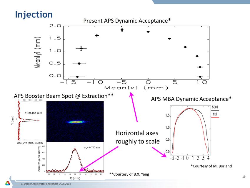
Injection Methods

Accumulation
 • Traditional injection scheme for light sources
 • Requires sufficiently large dynamic aperture (at injection point)
 • Smallest emittance lattices might have sufficient momentum
 aperture (lifetime) but not sufficient dynamic aperture
On-Axis Swap-out
 • Enables injection into small dynamic aperture
 • Bunch (or bunch-train) is replaces with fresh bunch (or bunch-train)
 • Recycle or dump spent bunches
 - Added complexity
 • Requires fast kickers to minimize fill pattern gaps
 - Might impact the range of possible fill patterns
 • In use for commissioning or damping rings
 • Many potential advantages
 55
Off-axis injection and accumulation
Traditional 4-kicker injection
 • Stored beam is kicked towards septum
 • Imperfect kicker bump results in transient orbit oscillations that can degrade beam
 quality for users during top-up injection
Pulsed multipole injection
 • Injected beam is kicked when passing off-axis through multipole magnet
 • Stored beam is unperturbed passing through center of multipole magnet

 Sirius

 56
On-axis injection

 inject here

 Longitudinal Injection
 requires fast kicker
 (width < bunch spacing)
 M. Aiba, M. Böge, Á. Saá
 Hernández, F. Marcellini and A.
 Streun, this conference

 Bunch Replacement (Swap-Out) Injection
requires fast kicker (width ~ bunch spacing or longer for
 pulse trains) - M. Borland, L. Emery, Proc. PAC’03
On-axis injection (swap-out)

 APS-U

 • flat top: 10s ns
 • rise/fall: few ns
 • rise/fall times
 determine length
 Swap-out injection was first proposed by M. Borland of gaps between
 for possible APS upgrades bunch trains
On-axis injection with accumulator (ALS-U)
 storage ring bunches transferred to accumulator
 accumulator bunches transferred to storage ring

 Fast kicker magnets

 New
  ALS
  storage
  ring


New
  accumulator
  ring
On-axis injection with accumulator (ALS-U) – cont.

On-axis injection:
• Further optimization of
 lattice (smaller emittance)
• Round beams (more useful
 shape and reduced
 emittance growth)
• Magnet field requirements
 relaxed (cost benefit)
• Vacuum chambers with
 small and round apertures
 (better undulator
 performance)
• Reduced injection losses
 (better performance)
iteration. The population is evolved generation by genera- A. Robust dynamic aperture
 tion until it converges or reaches the maximum number of tracking and quantification
 iterations. DA is usually defined as the maximum stable area in
 Figure 1 shows the last generation of objective func- transverse plane at injection point. Particles with initial
 tions, where we are maximizing both the on-momentum condition within this area will survive after a certain num-
 DA (horizontal axis) and the off-momentum DA (vertical ber of turns of tracking.
 axis). The trend of the optimization is that the whole Obviously, the area of this 2D bounded region alone
 population moves toward upper right, and converges to cannot represent the quality of DA. For different momen-

 4GSRs: why now? – accelerator physics
 lower rank. By this generation, the Pareto optimal has tum deviation " ¼ ðp ( p0 Þ=p0 , the stable area or DA may
 only three candidates at the upper right corner. In a be different. Larger on-momentum DA may help the in-
 realistic optimization, the full convergence may take too jection, while off-momentum DA helps Touschek lifetime.
 long to achieve, while stopping at a set of reasonably good One common way to calculate DA is particle tracking
 solutions which are sufficient for further applications is along several radial lines (see Fig. 2) with fourth-order or
 desirable. In Fig. 1, although the solutions are not fully even higher symplectic integrator [22]. An ideal solution of
 converged, they have many candidates with DA DA would have an elliptical type of shape with no cut-in
 >120 mm2 . It is a good starting point for detailed unstable area (as the two red points shown in Fig. 2).
 Because of betatron oscillation, particles are crossing the
 transverse plan at different ðx; yÞ coordinate, and after long
 enough time, they will be lost at the cut-in unstable area. A
 good searching method should have good precision to
 detect these cut-in unstable areas while not requiring too

 SymplecTc
  Tracking
  based
  methods

 much trial tracking near the DA boundary, since the track-
 ing is expensive in computing time. Based on this, we

 from L. Nadolski,
 DA,
  MA
  separated
   DA,
  MA
  together
   ICFA LowEring,
 FIG. 1. The last generation of objective functions: DA of on-
 Oxford 7/13
 momentum (horizontal axis) and off-momentum (vertical axis) FIG. 2. Larger DA area may not necessarily provide a better
 particles. Points are colored according to their rank. solution, unless it covers an ellipse fully.

Direct
  tracking
  based
  opTmizaTon

 054001-3
 GLASS
   AnalyTcal
  based
  method


 GeneTc
  Algorithm
   Lie
  Algebra/DifferenTal
  Algebra

 MOGA

 Resonance
  Driving
  Terms
   Amplitude
  Tuneshia

Frequency
  Maps

   RDT
  minimizaTon
   minimizaTon

 FMA
   Nonlinear

Diffusion
  factor
   Canceling
   Phase
  advances

 “LOCO”

 Sextupole

 Interleaved

 Resonance
  idenTficaTon
   Resonances


 sextupoles


 Robustness
  to
  magneTc,
  alignment
  errors
   Robustness
  ID
  configuraTons


 Tracking
  codes:
   PTC
   MADX
   TRACY
   AT
   LEGO
   OPA
   ELEGANT
Online Optimization of Nonlinear Dynamics for DLSRs
 X. Huang, SLAC
• Nonlinear dynamics challenges in DLSRs (4GSRs) make online lattice optimization
 and automatic tuning, based on beam measurements, desirable
• Many optimization algorithms considered. Robust Conjugate Direction Search
 (RCDS) method selected for speed of convergence.
• Beam-based RCDS
 correction of coupling and
 improvement of injection
 efficiency by nonlinear lattice
 optimization conducted on
 SPEAR. Coupling reduced to
 ~2 x 10⁻⁴; dynamic aperture
 increased from 15 mm to ~18 mm.
Conclusions:
• Online optimization provides an alternative to having an accurate simulation model.
• Having an accurate nonlinear model would benefit 4GSR operation.
• Having nonlinear optics monitors and a beam-based nonlinear optics calibration
 tool (non-LOCO) for 4GSRs would be useful.
4GSRs: why now? – cont.
Compact magnet and vacuum technology
• NEG-coated vacuum chambers enable small apertures to enable high magnet
 gradients
 Pioneered at CERN, used extensively at Soleil, and adopted for MAX-IV and
 Sirius MBA lattices
• Precision magnet pole machining for small aperture magnets, combined function
 magnets, tolerance for magnet crosstalk (developed extensively at MAX-Lab)
 MAX-IV
 Courtesy S. Leemans

 heater tape for
 in-situ NEG SPring-8
 bake-out Sirius concept
 K. Soutome
4GSRs: why now? – cont.

 MAX-IV
Laurent S. Nadolski
 Synchrotron SOLEIL - Beam Dynamics Group

 4GSRs: why now? – cont. nadolski@synchrotron-soleil.fr

 Version 1.3, February 2011

Other advances in accelerator and light source
technology NPAC 2010–2011 (v1.3) Laurent S. Nadolski Frequency Map Analysis 1 / 53

• Fast kickers for on-axis injection Introduction: Studying Nonlinear Dynamics
 Fast kickers (KEK ATF)
• Sub-micron e- BPMs and orbit feedback
 Nonlinear dynamics
• Accelerator and beam line component mechanical
 Complex dynamics
 I Higher order
 stabilizing systems ResonancesI

 Tunes shift with amplitudes
 I
 resonances
 detected by
 Chaos, instabilities
• Micron resolution single pass BPMs (non-linear lattice
 I
 turn-turn BPMs
 Instability thresholds
 I
 (A. Franchi)
 tuning)
 Need of an accurate way to compute frequencies. Fast
• “In-situ” magnet measurement and alignment methodsFourier Transform (FFT) is an efficient algorithm (Cooley-Tukey,
 1965) and a powerful way yet limited. Precision is 1/T . To get
 (e.g. NSLS-II) high precision frequencies (tunes), very long integration, many
 data, or turns are needed.

• Mode-damped RF cavities (fundamental and harmonic)
 NPAC 2010–2011 (v1.3) Laurent S. Nadolski Frequency Map Analysis 2 / 53
 SPring-8 concept based on NSLS-II
• Highly stable solid state RF power sources vibrating wire method - K. Soutome
 Delta undulator
 prototype - A. Temnykh

• High performance IDs (superconducting,
 Delta, RF, etc.) SC undulator development at
 LBNL (S. Prestemon et al.), APS
 (E. Gluskin et al.) and elsewhere
SR design – short bunches
• There is a storage ring user community interested in short bunch
 experiments that probe materials properties on the >~10 ps time scale.
 Bunch lengths of order 10 ps are desirable, but longer bunches are also
 useful for longer time scales.
• Short single pulses are needed for pump-probe experiments with rep
 rates up to a few MHz (laser rep rate limit).
• Single bunches are often isolated in a gap in the bunch fill pattern
 (“camshaft mode”), but some rings run in a “timing mode” with a few
 widely space bunches. Spacing is sufficient for material transient
 response to decay. Photon pulse optical gating can also be used to
 select single pulses in some cases. Charge per bunch is limited in
 4GSR lattices by instabilities and IBS effects.
• Bunch current is greatly reduced in low momentum compaction lattices.
• Very short photon pulses (~100 fs) can be generated with laser slicing,
 but the number of photons per pulse is very low (~105?).
SR design – short bunches – cont.

• ALS has developed a “pseudo single bunch” kicking mechanism the
 puts one bunch on an oscillating orbit where its radiation is viewed in
 an apertured beam line that only sees light when the bunch is at an
 oscillation maximum.
• APS was considering a superconducting crab cavity scheme that
 would produce large charge, high rep rate short bunches in a
 localized part of the ring.
• BESSY-II proposed a 2-freq RF system to generate alternating short
 and long bunches. High frequency (~1.5 GHz), high voltage RF
 systems are needed.
• Exotic bunch manipulation schemes (e.g. emittance exchange, crab
 cavities, etc.) might be used in the future to produce temporary short
 bunches.
• Long bunches are desirable for 4GSRs to reduce IBS effects and
 emittance (harmonic cavity bunch lengthening).
Short bunches with low a in SPEAR3 – synergy with LCLS

 68
Simultaneously long & short bunches

 present nc-cavity (power) sc-cavity # 1 (focusing) sc-cavity # 1 & 2 (focusing)

 short short & long bunches
 long bunch
Voltage / MV

 bunch

 sum voltage

 rel. long. phase position / ns
 0.5 GHz, 1.5 MV 1.5 GHz, 25 MV 1.75 GHz, 21.4 MV
 V’=Vxfrf= 0.75 MVGHz V’=Vxfrf= 37.5 MVGHz V’ = Vxfrf= 75 MVGHz

 - flexible fill pattern, I
Short and long bunches with 2 RF frequencies
SPEAR3 future short bunch operation

 71
Ultimate storage rings?

• The term “ultimate storage ring” was first use in 2000:
 A. Ropert, J.M. Filhol, P. Elleaume, L. Farvacque, L. Hardy, J. Jacob, U. Weinrich, "Towards
 the Ultimate Storage Ring-Based Light Source", Proc. EPAC 2000, Vienna.
• “Ultimate” inferred reducing emttance towards the diffraction limit for X-rays
• “Ultimate” may have many meanings, including
 providing everything for every user
• One way to make storage rings more “ultimate”:

 FELs becoming more ring-like: higher rep
 rate, reduced photons/pulse (e.g. NGLS)
 Can rings become more FEL-like: increased
 ph/pulse, reduced energy spread, short
 pulses, lasing?
 Longitudinal and transverse transform-
 limited beams?
Light source performance: other metrics

 J. Corlett, R. Hettel, “Performance
 Requirements and Metrics for Future X-
 ray Sources”, Proc. PAC09, Vancouver
SASE with transverse gradient undulator E = 4.5 GeV εx/y=160 / 1.6 pm δE/E = 1.6x10⁻³ rms Q = 0.75 nC ηy = Ver?cal 0.05 m βx/y = 16 / 50 m σβ = 52 mm ση = 78 mm λu = 3 cm K = 3.7 TGU σz= 1ps Ipk = 300 A λph = 1.5 nm Bunch switched into FEL bypass ID grad = 22.9 m-1 (10-‐100 kHz) Z. Huang, Y. Cai, Y. Ding IPAC 2013 1.5 nm pulse energy = 0.5 mJ Reduce longitudinal emiQance to reach high peak current – a challenge for future ring designers! 8 CEBAF SC caviTes in a cryomodule produce 108 MV for longitudinal focusing Hard XFEL oscillator? – K-J Kim
Towards the ultimate

 Will ERLs rise up?

 transform-limited beam in 3 dimensions
4GSR design – comments

Brightness/coherence vs. flux
• User community is divided – some need flux, not brightness
• Figure of merit: number of “usable” photons per unit time in the spatial and energy
 bandwidth acceptance phase space of the experiment (e.g. protein crystal angular
 acceptance is quite large – moderate brightness is OK). “Brightness isn’t everything”.
• Diminishing return on coherent fraction and flux as emittance is reduced
• Cost-performance optimization needed for every light source design
• Science case should drive the optimization (is 10 or 1 pm worth it? – maybe!)

Lattice 16 beam lines in PEP-X with 7BA
 (left) and DBA/TME hybird (right)
• ID straight section length is always an issue (canted IDs?)
• Spacing between ID straights is an issue with large
 rings, leading to large, expensive experimental halls.
 Consolidating beam lines with hybrid lattice BRIGHTNESS

 may be more efficient (e.g. PETRA-III)
• A relaxed, larger dynamic aperture mode
 for aggressive lattices?: “emittance knob”
A new generation of storage ring light sources
Appendix 1

 4GSR R&D Topics
4GSR R&D: lattice design

Low emittance, buildable lattices: Develop low emittance lattice designs having
“reasonable” multipole gradients and magnet apertures. Explore benefit of using
dipoles with longitudinal gradient.
Design optimization: Develop algorithms for optimizing ring parameters (e.g.
energy, emittance, circumference, beta functions, RF, etc) based on targeted
spectral brightness, coherence, special operating modes (e.g. short bunches,
lasing) and number of beam lines. Define a quality factor to gauge this optimization.
Consolidated beam lines: Develop lattice geometries, potentially non-circular and/
or having hybrid lattices, that enable consolidating beam line straight sections in
very large rings – a part of design optimization.
Robinson wigglers: Are they a preferred replacement for conventional damping
wigglers in reducing emittance?
Round beams: Determine optimal ways to produce nearly round beams at source
points. Test on existing machines if possible.
Momentum compaction: Develop very low emittance lattices with increased
momentum compaction as a way to increase bunch length (e.g. chicanes, etc.).

 79
4GSR R&D: accelerator physics

Simulation codes: Develop codes that account for close magnet spacing and
include collective effects during lattice optimization. Improve simulation codes
impedance, ion instability, CSR and other effects as needed. Benchmark codes
on existing machines operating in special modes.
Scaling laws: Develop general scaling laws that take into account as much as
possible all the effects, including emittance (with collective effects), brightness,
spectrum, circumference, magnet strengths, RF, running costs, etc.
Non-linear lattice correction: Develop improved techniques to measure and
correct higher order resonance driving terms to maximize dynamic apertures. Test
on existing rings.
RF frequency: Study the benefit of higher RF frequency for reducing longitudinal
emittance, bunch length and operating costs, and the use of using 2 frequencies
to generate alternating long and short bunches.

 80
4GSR R&D: accelerator physics – cont.

Reduced energy spread, longitudinal emittance: Explore ways to reduce
energy spread (to the level of 0.05% or less), and longitiudinal emittance in
general, to enable using high ID harmonics, short bunches and potential lasing.
High peak current: Explore ways to produce >200 Apk with 10 pm-scale
emittance to enable lasing.
Lasing: Determine beam parameters and consequent ring designs that would
enable X-ray FEL operation, either in a switched bypass or in the ring itself,
including oscillator configurations.
Beam manipulation: Explore ways to (locally) reduce emittance, bunch length,
energy spread, etc. (e.g. emittance exchange, flat-to-round converter (ID in
solenoid), RF and optical manipulation methods, etc.).
Very short bunches and CSR: Explore ways to suppress CSR to reduce the
lengthening and emittance increase of very short bunches propagating in the ring.
Space charge: Determine if space charge is an issue for low-E USRs.

 81
4GSR R&D: injection

SIngle-shot top-up: Ways to restore charge to multiple arbitrary bunches in a
single injection shot to reduce the duration of the top-up-related orbit transient,
maintaining variation in charge for all bunches to ~20% or less for a uniform fill
pattern.
Pulsed multipole (PM) injection: Continued development of PM injection
schemes, including schemes with septum and PM in the same straight.
Accumulator/booster for swap-out injection: Study the practicality of
implementing a combined accumulator/booster, possibly located in the main ring
tunnel, for realizing multibunch single-shot swap-out injection. Investigate the
possibility of recovering the beam kicked out from the ring in the accumulator/
booster for reinjection.
Injection kickers: See Accelerator Engineering
Longitudinal injection: Investigate practicality of longitudinal injection as a way to
eliminated stored beam orbit transient.

 82
4GSR R&D: accelerator engineering

Magnets: Determine optimal magnet bore dimensions with respect to mechanical
tolerances, multipole strengths, yoke saturation and vacuum system design.
Investigate magnet material choice, solid versus laminated cores and compact
combined function magnet designs.
Vacuum system: Designs for small aperture vacuum systems with focus on
chamber material, NEG coating and activation processes, heat absorption,
synchrotron light extraction and BPM head stability.
Stability: Develop site vibration specifications for USRs. Develop passive and
active ways to minimize effects on the stability of the photon beam and critical
accelerator and beam line components caused by ground motion, cooling water,
machine- and temperature-induced motion and vibration. Develop stable builiding
design concepts.
Motion sensors: Develop affordable 100-nm-resolution component motion
sensors.
Alignment: Develop practical and simplified ways to achieve 10-µm alignment
tolerances.

 83
4GSR R&D: accelerator engineering – cont.

RF system: Optimal frequency(s), improved cavity mode damping, solid state
amplifiers, harmonic cavity systems (including passive vs. active), crab and other
beam manipulation cavities, solid state RF power sources, continued
improvements to LLRF.
Power supplies: Not discussed.
Pulsed multipole injection magnets: Designs that reduce the required
separation of injected and stored beams.
Fast kickers: Develop injection kicker and pulser designs having
4GSR R&D: instrumentation and feedback

e- BPMs: Stable BPM designs for small aperture vacuum chambers having micron
turn-turn resolution or better.
BPM processors: A factor of 10 or more increase in turn-turn resolution than
present state-of-the-art for measurement of higher order lattice resonance driving
terms; reduced processing latency to be commensurate with 10-kHz digital
feedback clock rates; improved stability and reduced current dependence.
X-ray BPMs: Continued development of photon BPMs for IDs, especially EPUs
and VUV.
Orbit feedback: Integrated orbit and beam line component feedback systems to
achieve maximal beam stability at the experiment using multiple sensor types (e.g.
e-BPMs, X-BPMs, beam line sensor and detector information, motion monitors, etc).
Beam size stabilization: Feedback and feedforward systems to stabilize beam
size as IDs, especially EPUs, are varied.
Multibunch feedback: Improved systems having higher resolution, reduced noise
impact and capable of accommodating variable bunch fill patterns, including ones
with single large bunches and many small ones.

 85
4SR R&D: insertion devices

New IDs: Continue ongoing R&D on CPMUs, SCUs, variable polarization and
other new IDs will benefit USRs.
ID length: Establish optimal lengths for IDs in USRs; straight section lengths
should be determined accordingly.
Small gaps: Determine minimum ID gaps.
Vertically oriented IDs: Can they be accommodated (e.g. Delta-type, helical,
TGUs, etc.)?
Power on optics: Develop improved masking schemes and IDs that minimize
unused power on optics.
Dynamic effects: Establish ID tolerance requirements and study effects of
present and anticipated future IDs and USR beam dynamics and properties and
develop effective compensation schemes.
ID commissioning: Develop new ID commissioning strategies as needed for
USRs; test on existing machines.
X-ray optics: Develop X-ray optical components capable of preserving photon
beam properties, including coherence, from USR IDs.

 86
Appendix 2

 4GSR Accelerator and Science
 Reference:
 Journal of Synchrotron Radiation (2014) 21
JSR (2014) 21 - contents

Diffraction limited storage rings - how and why?
 M. Eriksson, C. Quitmann, J.F. van der Veen
DLSR projects and plans, an international overview R. Hettel
Lattice design challenges for fourth-generation storage ring light sources
 M. Borland, G. Decker, L. Emery, V. Sajaev, Y. Sun and A. Xiao
Magnet design for a low emittance storage ring

 M. Johansson, B. Anderberg, L-J Lindgren
DLSR vacuum technology E. Al-Dmour, J. Ahlbäck, D. Einfeld, P. F. Tavares, M. Grabski
First multi-bend achromat lattice consideration D. Einfeld, M. Plesko, J. Schaper
Collective effects in DLSR R. Nagaoka, K.L.F. Bane

The MAX IV storage ring project P. Tavares, S. Leemann, M. Sjöström, Å. Andersson
The Sirius project L. Liu, N. Milas, A.H.C. Mukai, X. R. Resende, A.R.D. Rodrigues,
 F.H. de Sá
Short bunches in diffraction limited storage rings X. Huang, T. Rabedeau, J. Safranek
JSR (2014) 21 – contents – cont.
Coherent imaging at the diffraction limit P. Thibault, M. Guizar-Sicairos, A. Menzel
Hard X-ray scanning microscopy Christian Schroer, G. Falkenberg
XPCS and coherent imaging of fluctuating condensed matter O. Shpyrko
X-ray nanoprobes and diffraction limited storage rings: opportunities for
 fluorescence tomography of biological specimens M. de Jonge. C. Jacobsen
Structural Biology in the 21st Century R.F. Fischetti, B.K. Kobilka, J.L. Smith, W.I. Weis
High resolution resonant X-ray inelastic scattering studies of materials, liquids and gases
 T. Schmitt, F. de Groot, J-E Rubensson
NanoARPES investigations of heterogenous correlated electron systems E. Rotenberg
X-ray spectroscopy for chemical and energy sciences A.I. Frenkel, J.A. van Bokhoven
Reciprocal and real space spectromicroscopy and imaging with diffraction limited
 X-ray sources with focus on energy materials applications M. Toney, A. Hitchcock
High pressure science on diffraction limited storage rings M.I. McMahon
Pixel detectors for diffraction-limited storage rings B. Schmitt, P. Denes
Optics for coherent X-ray applications M. Yabashi, K. Tono, Hidekazu Mimura, K. Yamauchi,
 K. Tamasaku, H. Ohashi, S. Goto, T. Ishikawa
New challenges in beamline instrumentation for Diffraction Limited Storage Rings
 J. Susini, R. Barrett, C. Morawe, P. Fajardo
On the characterization of ultra-precise X-ray optical components – advances and
 challenges in ex-situ metrology F. Siewert, J. Buchheim, T. Zeschke, M. Störmer, R. Sankari
Appendix 3

 Low Emittance Ring
 and 4GSR Workshops
4GSR Workshops

• ICFA Future Light Source Workshops (especially over last few years)
• ICFA Low Emittance Rings Workshops (LowERing)
• XDL 2011 Workshops for ERLs and DLSRs, Cornell, June 2011
• Beijing USR Workshop, Huairou, October 2012
• DLSR Workshop, SPring-8, December 2012
• DOE BESAC Subcommittee on Future Light Sources, July 2013
• Low Emittance Ring Workshop, Oxford, July 2013
• SLAC DLSR Workshop, SLAC, December 2013
• Workshop on Advances in Low Emittance Rings Technology
 (ALERT 2014), Valencia, May 2014
• Low Emittance Rings Workshop (LER2014), Frascati, September 2014
• DLSR Workshop, Argonne, November 2014
 many other workshops on low emittance rings, including those in
 the past for ILC damping rings
SR design optimization Light Source Design ID reqmts SR properties impedance acceptance injection energy emittance dp/p lifetime BSC coupling stability geometry e-‐ beam dimen dyn ap current ID comp lattice fns orbit ctrl Install/align facilities I&C RF pwr supplies beam lines supports vac pump magnets IDs vac chamb/absorb R. Hettel Draft SPEAR 3 Design rev 1 Jan. 17 2003
You can also read