Design Criteria Manual & Supplementary Specifications - WATER METER and SERVICE CONNECTION
←
→
Page content transcription
If your browser does not render page correctly, please read the page content below

ENGINEERING DEPARTMENT

WATER METER and SERVICE CONNECTION

           Design Criteria Manual &
        Supplementary Specifications
                              May 2020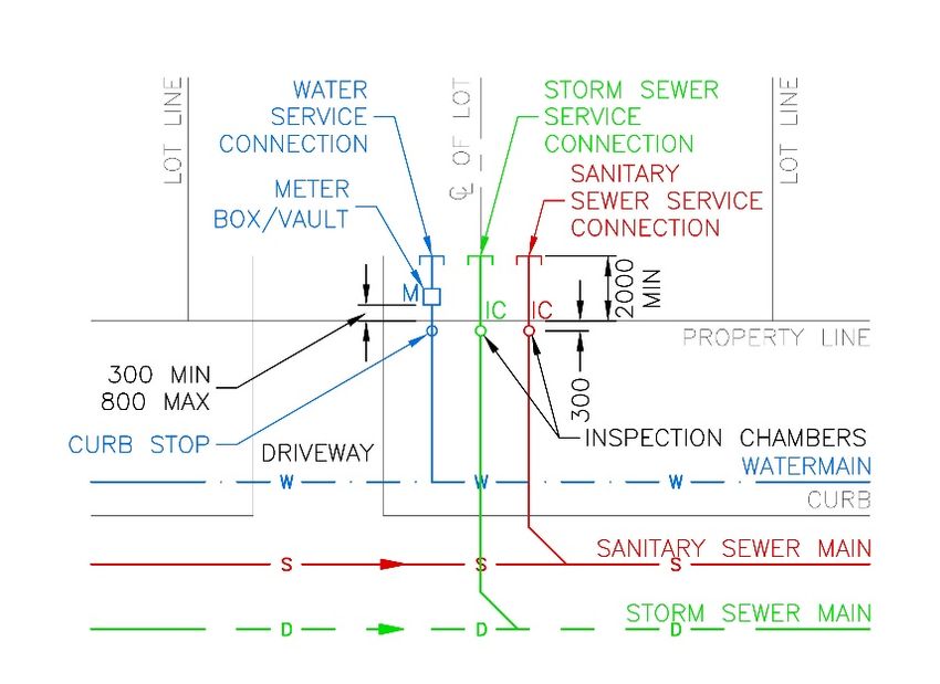
City of Surrey          WATER METER and SERVICE CONNECTION
Engineering Department
Design Criteria Manual & Supplementary Specifications                                May 2020

                                SCHEDULE OF REVISIONS

                               Description                                     Page

Preamble
Responsibilities – Clarification is provided that the City supplies and
                                                                                i
installs meters up to 25 mm diameter.
Timing – The Applicant’s responsibility to keep the meter area clear and
protect the meter installation from damage throughout the duration of the       ii
project is reinforced.
Design Criteria Manual
Service Connection Sizing – Clarification is provided regarding domestic
service connection sizing requirements as well as its separation                1
requirements from fire services.
Meter Location – Direction is provided regarding meter location
requirements for developments with no or limited setback from property          2
line.
Meter Location – An illustration is provided to depict the meter box / vault
location requirements relative to property lines and lot features such as       2
driveways.
Meter Location – The requirement to keep the area immediately adjacent
                                                                                3
to the meter box / vault clear and accessible is highlighted.
Meter Configuration – Additional commentary is provided regarding
placement of ancillary water infrastructure components upstream or              3
downstream of the meter.
Isolation Valves – Greater flexibility is provided regarding valve location
                                                                                3
relative to the meter chamber.
Reducers – Clarification is provided regarding acceptable means of
                                                                                3
achieving pipe size reductions.
City of Surrey          WATER METER and SERVICE CONNECTION
Engineering Department
Design Criteria Manual & Supplementary Specifications                                  May 2020

                               Description                                       Page

Bypasses – A table is provided with required bypass sizes for
corresponding meter sizes. The requirement to close and seal the bypass            4
valve upon completion of the meter installation is also highlighted.
Remote Receptacles – The requirement to have recessed circular openings
in box / chamber lids such that the remote receptacle is flush with the lid        4
is highlighted.
Meter Configuration – An illustration is provided to depict meter
configuration options for consideration, specifically location options for         5
isolation valves, reducers, and bypass tees relative to the chamber.
Supplementary Specifications
Water Meters – The list of approved water meters is revised.                      SS-1
Reducers – A subsection is added to indicate acceptable reducer types.            SS-2
Chambers – Alternate box materials are added for meter installations up
to 25 mm. Lid materials and configurations that are not acceptable are also       SS-3
highlighted.
Meter Installation – The requirements to orient the register face such that
                                                                                  SS-3
it is easily visible and to centre the meter within the box are highlighted.
Appendices
Appendix A – The meter sizing table in Step 6 of the meter sizing
                                                                               Appendix A
calculation sheet is updated.
Appendix B – Service connection sizing is introduced.                          Appendix B
Appendix C – A meter and service connection sizing example is provided.        Appendix C
Appendix D – The Supplementary Detail Drawings are updated.                    Appendix D
City of Surrey          WATER METER and SERVICE CONNECTION
Engineering Department
Design Criteria Manual & Supplementary Specifications                                                                                   May 2020

                                                     TABLE OF CONTENTS

 PREAMBLE ................................................................................................................................ i
    Introduction ........................................................................................................................... i
        Intent ...................................................................................................................................... i
        Glossary of Terms ................................................................................................................. i
        Responsibilities .................................................................................................................... ii
        Timing .................................................................................................................................. ii
 DESIGN CRITERIA MANUAL ............................................................................................... 1
    A. Meter Sizing Methodology ........................................................................................... 1
        B. Service Connection Sizing Methodology ..................................................................... 1
        C. Meter Selection ............................................................................................................. 2
        D. Meter Location .............................................................................................................. 2
        E.     Meter Configuration...................................................................................................... 3
               i.     Isolation Valves ..................................................................................................... 4
               ii.    Reducers ................................................................................................................ 4
               iii. Bypasses ................................................................................................................ 4
               iv. Setters .................................................................................................................... 5
               v.     Test Ports ............................................................................................................... 5
               vi. Remote Receptacles .............................................................................................. 5
               vii. Chambers ............................................................................................................... 5
        F.     Submissions .................................................................................................................. 6
 SUPPLEMENTARY SPECIFICATIONS ..........................................................................SS-1
 1.0 PRODUCTS...................................................................................................................SS-1
     1.1 Water Meters ............................................................................................................SS-1
        1.2 Registers ...................................................................................................................SS-1
        1.3 Remote Receptacles .................................................................................................SS-2
        1.4 Pipe and Fittings ......................................................................................................SS-2
        1.5 Valves ......................................................................................................................SS-2
        1.6 Reducers ...................................................................................................................SS-2
        1.7 Setters .......................................................................................................................SS-3
City of Surrey          WATER METER and SERVICE CONNECTION
Engineering Department
Design Criteria Manual & Supplementary Specifications                                                                        May 2020

        1.8 Flange Adapters .......................................................................................................SS-3
        1.9 Bolts and Nuts ..........................................................................................................SS-3
        1.10 Chambers .................................................................................................................SS-3
 2.0 EXECUTION ................................................................................................................SS-4
     2.1 Meter Installation .....................................................................................................SS-4
        2.2 Receptacle Installation .............................................................................................SS-4
 3.0 SUPPLEMENTARY DETAIL DRAWINGS .............................................................SS-5
     3.1 Supplementary Detail Drawings ..............................................................................SS-5

APPENDICES
APPENDIX A              Water Meter Sizing Calculation Sheet
APPENDIX B              Service Connection Sizing Calculation Sheet
APPENDIX C              Water Meter and Service Connection Sizing Calculation Example
APPENDIX D              Supplementary Detail Drawings
City of Surrey WATER METER and SERVICE CONNECTION
Engineering Department Page i
Design Criteria Manual & Supplementary Specifications May 2020
PREAMBLE
Introduction
This document outlines the City’s requirements for the installation of cold-water meters and
service connections. It is divided into two separate parts, the Design Criteria and the
Supplementary Specifications.
Intent
The Design Criteria are intended to provide direction to the Applicant and Consultant on the
elements required to be considered in the design of new service connection and water meter
installations. It is intended to be used in conjunction with the City of Surrey Design Criteria
Manual.
The Supplementary Specifications are intended to provide direction to the Applicant and
Consultant on the specifications that must be incorporated into building servicing contracts for the
installation of new water meters. The Supplementary Specifications are to be used in conjunction
with the City of Surrey Supplementary Specifications document and the City approved edition of
the Master Municipal Construction Document.
Glossary of Terms
“Applicant” Refers to a property Owner, Developer, or authorized agent who
makes an application for connection to a water service.
“Consultant” As defined in the latest City Design Criteria Manual.
“ASTM” Refers to the American Society for Testing and Materials.
“AWWA” Refers to the American Water Works Association.
“City” Means the City of Surrey.
“CSA” Means the Canadian Standards Association.
“Developer” Means person(s) or organization(s) developing property as per City
guidelines.
“General Manager Means the General Manager or their appointed designate of the
Engineering” Engineering Department of the City.
“NFPA” Refers to the National Fire Protection Association.
“Owner” Means the property Owner as defined by the latest Surrey
Waterworks Regulation and Charges By-law.City of Surrey WATER METER and SERVICE CONNECTION Engineering Department Page ii Design Criteria Manual & Supplementary Specifications May 2020 Responsibilities The Surrey Waterworks Regulation and Charges Bylaw, 2007, No. 16337 (as amended) outlines metering requirements for specific scenarios. For all new and replacement service connections, the Developer shall supply and install all piping, valves, and fittings required at the Developer’s cost. For all new connections, the Applicant must supply and install all piping, fittings, meter box(es) / chamber(s) / vault(s), and equipment. The City supplies and installs 19 mm and 25 mm meters for single-family and duplex residential construction at the Applicant’s cost. All other meters, including permanent, temporary, and construction service meters, are supplied and installed by the Applicant. Backflow prevention devices, although not covered within this document, are to be installed in accordance with Surrey Waterworks Cross Connection Control Bylaw, 2013, No. 17988 (as amended). Timing The installation of any new or replacement service connections is triggered by the Applicant request as either part of a Land Development or Building Permit process. As part of the process, except for a single-family and duplex residential development types, the Applicant shall submit a calculation to estimate the service connection size, and the City shall confirm the appropriate service connection size and location. For new connections, the installation of a water meter is triggered by an application for a Building Permit or Plumbing Permit. Following the issuance of the Building Permit, the Applicant and City shall confirm the meter size and location within the property and relative to any structures. For new single-family residential dwellings, water meter boxes, setters, and lids are to be installed by the Applicant and approved by the City Plumbing Inspector prior to City installation of the water meter. The meter area must be kept free and accessible at all times in order to facilitate the installation of the meter. The Applicant is responsible for protection of the meter installation from damage throughout the duration of the project (until the City Plumbing Inspector has approved the installation) and must repair any damage that occurs to the box, setter, meter, or lid. The Applicant shall ensure that the meter box and lid are adjusted to final grade and remain unobstructed to facilitate maintenance, reading, and testing.
City of Surrey          WATER METER and SERVICE CONNECTION
Engineering Department                                                                  Page iii
Design Criteria Manual & Supplementary Specifications                                  May 2020

For proposed installations of 50 mm or larger meters (where a drawing submission is required as
per Design Criteria Manual Section F) installation of the water service, chamber, or meter within
private property shall not begin prior to City approval of the meter design drawings.
City of Surrey         WATER METER and SERVICE CONNECTION
Engineering Department                                                                        Page 1
Design Criteria Manual                                                                      May 2020

                                DESIGN CRITERIA MANUAL

A.   Meter Sizing Methodology

     For all single-family residential homes without fire sprinklers, the water meter size shall be
     19 mm, except in the case where the Consultant can demonstrate the need for a larger water
     meter. All other meters should be sized in accordance with AWWA M22 Sizing Water Service
     Lines and Meters and the City of Surrey Water Meter Sizing Calculation Sheet contained in
     Appendix A. It should be noted that this methodology is based on the AWWA fixture value
     method and not the fixture unit method employed in the BC Building Code for piping within
     buildings.

     For developments that are proposed to be phased, the meter chamber and piping must be
     sized for the meter required for the ultimate build-out of the development; however, the
     initial meter installed must be sized to accurately capture the range of flows for the first
     phase.

     The Applicant or Consultant must ensure that the meter selection and installation
     requirements are appropriate for the designed application without unnecessarily oversizing
     the meter or restricting water pressure.

B.   Service Connection Sizing Methodology

     Only one service connection is allowed for each legal lot, unless under specific
     circumstances where prior approval from the City must be obtained.

     For lots with onsite fire sprinkler or fire hydrant requirements, domestic and fire service lines
     are to be separated, either at the property line or at the main, as determined by the City. A
     domestic water meter is to be installed at the domestic line and a detector meter backflow
     preventer is to be installed at the fire line, as outlined in the Surrey Waterworks Cross
     Connection Control Bylaw, 2013, No. 17988 (as amended). The exception to this is for
     single-family residential homes that employ fire sprinklers. In this case, a combined
     domestic and fire service line is acceptable.

     For all single-family residential homes (regardless of the lot’s zoning) without fire
     sprinklers, the service connection size shall be 19 mm or 25 mm, except in the case where
     the Consultant can demonstrate the need for a larger service connection. For all duplex,
     triplex, and four-plex homes, a separate 19 mm service connection is allowed for each unit.
City of Surrey WATER METER and SERVICE CONNECTION
Engineering Department Page 2
Design Criteria Manual May 2020
The domestic service connection for other types of development, i.e., multi-family,
industrial, commercial, and institutional lots, is to be sized in accordance with the City of
Surrey Water Service Connection Sizing Calculation Sheet contained in Appendix B of this
document. This calculation sheet is modified based on AWWA M22 Sizing Water Service
Lines and Meters. This calculation method does not include any fire service connection, if
required by the development.
It should be noted that this methodology is based on the AWWA fixture value method and
not the fixture unit method employed in the BC Building Code for piping within buildings.
For developments that are proposed to be phased, the service connection must be sized for
the ultimate build-out of the development.
C. Meter Selection
Meters approved for use in the City are listed in Section 1.1 of the Supplementary
Specifications.
Only one domestic meter is to be supplied per property unless otherwise approved by the
City. The only exception is duplex, triplex, or four-plex units where separate domestic meters
are to be provided for each unit.
When a combined domestic/fire service connection is installed for a single-family home with
sprinklers, the meter must be approved for fire protection applications as indicated in
Section 1.1 of the Supplementary Specifications.
D. Meter Location
All meters 50 mm and smaller must be located at the property line in a chamber unless
otherwise approved by the City.
For developments with no or limited setback from property line, such as City Centre, the
meter shall be installed inside within 1.0 metre of the exterior wall and within 0.5 metres of
the ceiling. Pipe supports, hangers, straps, or similar shall be provided to appropriately
support the meter. The meter location must be accessible for City staff with the register face
oriented such that it is clearly visible.
For property line installations, the meter box or vault must be located on private property,
within 300 mm to 800 mm from the property line as indicated on Supplementary Detail
Drawing SSD-WM1 and depicted in the illustration below.City of Surrey WATER METER and SERVICE CONNECTION
Engineering Department Page 3
Design Criteria Manual May 2020
Water meters shall not be installed within any utility right-of-way unless such right-of-way
is designated for a water meter installation. Grading of the area around the chamber must
ensure positive drainage away from the chamber.
An area of at least 1.0 metre horizontal and 2.0 metre vertical around the meter box or
vault shall be free of major landscaping or objects, including shrubs, fences, gate
tracks, retaining walls, etc., to facilitate future maintenance of the meter assembly.
Where the meter is approved to be installed within a building, the installation should be
within 1.0 metre of the exterior wall. The meter should also be within a reasonable distance
of a floor drain, which must be suitably sized to accept the flows associated with meter
testing. The meter should be installed a minimum of 600 mm above the floor slab. A space
of at least 1.0 metre horizontal and 1.0 metre vertical from the meter assembly shall be free
of obstruction to allow for convenient servicing and testing of the meter at all times. No
electrical, mechanical, or water-sensitive equipment should be placed or installed under the
meter assembly or in an area where splash or flow from the meter assembly could occur
during servicing of the meter.
E. Meter Configuration
The general configuration for single-family residential meter installations is illustrated on
Supplementary Detail Drawing SSD-WM1. For all meters 50 mm and larger, configuration
details shall be determined by the Consultant and outlined in the submittal drawings.City of Surrey WATER METER and SERVICE CONNECTION
Engineering Department Page 4
Design Criteria Manual May 2020
For all meters 50 mm and larger, adequate straight length pipe shall be provided upstream
and downstream of the meter in order to comply with manufacturer recommendations for
maximum accuracy. Bypass tees, isolation gate valves, and concentric reducers may be
located within the straight pipe length distance in accordance with manufacturer
recommendations. Non-concentric reducers, check valves/backflow preventers, pressure
reducing/sustaining or altitude valves, throttling devices or similar shall not be located within
four pipe diameters of the meter. A restrained coupling must be provided on the downstream
side of the meter to facilitate meter removal for replacement/maintenance.
i. Isolation Valves
Isolation valves are required to be installed upstream and downstream of the meter
assembly. Isolation valves shall be the same size as the incoming and outgoing service
connection.
Isolation valves may be located in the same chamber as the meter, or outside of the
chamber with MR6 valve boxes. In all cases, isolation valves must be accessible to
City staff and free of obstructions to facilitate operation.
ii. Reducers
Reduction in the size of the incoming or outgoing water service connection must occur
between the isolation valves.
Reduction must be achieved using concentric reducers. Use of threaded blind flanges
to transition to smaller pipe size is not acceptable.
iii. Bypasses
A bypass is required to be installed on all 50 mm and larger meters.
The bypass size shall be as per the table below:
Table A – Bypass Size
Water Service Connection Bypass Size
Size (mm) (mm)
50 1 25
100 50
150 50
1
Bypass may be part of setter.City of Surrey WATER METER and SERVICE CONNECTION
Engineering Department Page 5
Design Criteria Manual May 2020
The bypass valve must be accessible to City staff and free of obstructions to facilitate
operation.
After completing the meter installation, the bypass valve must be closed and
sealed.
Bypasses must not be located directly above the meter in a chamber setting; however,
rotating the bypass 45 degrees is permitted if space governs.
iv. Setters
Setters are only permitted for water meters 50 mm diameter or smaller and must be the
same size as the water service connection.
v. Test Ports
Test ports must be provided for all meter assemblies 50 mm diameter or larger. In the
absence of a test port on the meter case, a test tee must be installed at a distance of
three pipe diameters downstream of the meter.
vi. Remote Receptacles
For exterior meter installations, remote receptacles must be mounted to the chamber
lid.
The chamber lid must have a recessed circular opening such that the top of the
remote receptacle is flush with the lid.
At least 1.8 metres of 22 gauge, three-colour (red, green, black) wire shall be provided
between the remote receptacle and meter. Remote wiring connections shall be factory
or field sealed to ensure that the connection is waterproof.
For inside meter installations, where approved by the City, wall mounted remote
receptacles should be located approximately 1.6 metres above grade and easily
accessible for reading. Where possible, remote receptacles should be located adjacent
to gas or electric meters. For all inside meters, the remote receptacle shall be equipped
with a radio transmitter end-point.
vii. Chambers
Meter chambers must be selected to provide adequate space for removal and testing of
all equipment within the meter assembly, including backflow prevention devices
where applicable.City of Surrey WATER METER and SERVICE CONNECTION
Engineering Department Page 6
Design Criteria Manual May 2020
Access lids, latches, and ladders must comply with the current requirements of
WorkSafeBC.
Thrust beams must be designed for all chambers housing equipment 75 mm or larger
to ensure that the thrust force is transferred to the full width of the chamber. The
Consultant shall ensure that the chamber manufacturer is in agreement with the thrust
bearing area on the chamber.
All chambers for meters 75 mm and larger must be equipped with a sump and drained
by either a gravity connection to the storm sewer, or where this is not possible by a
sump pump. The Owner is responsible for providing power to the sump pump in
accordance with the BC Electrical Code.
The illustration below depicts meter configuration options (Option A, B, and C in the
figure) that the Applicant or Consultant may consider.
F. Submissions
For all meters 50 mm and larger, the Plumbing Permit Application submitted by the
Applicant shall be accompanied by:
• A site plan at 1:500 scale and chamber layout at 1:250 scale;
• Location of meter chamber relative to overall site development plan (dimensioned
from property corner);
• Future phasing of the project;
• Meter size, type, and manufacturer;
• Demand flow calculations in accordance with Appendix A;
• Chamber drain type and discharge location;City of Surrey WATER METER and SERVICE CONNECTION
Engineering Department Page 7
Design Criteria Manual May 2020
• Site specifics (i.e., building use);
• On-site fire system (hydrants, fire sprinklers);
• Irrigation systems; and
• Any other relevant information pertaining to the proposed meter installation.
For all meter assemblies 50 mm and larger, the Consultant must provide sealed design
drawings and shop drawings of the complete meter installation and relevant calculations, to
demonstrate the appropriateness of the sizing of the meter, for City approval prior to
installing the meter. A meter chamber design drawing template is provided in Appendix D
(SSD-WM2).City of Surrey WATER METER and SERVICE CONNECTION
Engineering Department Page SS-1
Supplementary Specifications May 2020
SUPPLEMENTARY SPECIFICATIONS
1.0 PRODUCTS
1.1 Water Meters .1 Unless a variation is justified, the City will only accept approved
makes and models of water meters. The following meters are
approved by the City:
Table 1 – Approved Meters
Manufacturer Model Sizes
iPERL 25 mm and smaller
Sensus iPERL Fire Service 1 25 mm only
OMNI C 2 50 mm and larger
Recordall PD 50 mm and smaller
Badger E-Series 19 mm and larger
1
E-Series Fire Service 25 mm to 50 mm
T-10 50 mm and smaller
Neptune
MACH 10 1 50 mm and smaller
1
Approved for use on water service connections supplying
residential homes with fire sprinklers.
2
Alternate meters may be accepted, but must be approved by
the General Manager, Engineering.
.2 All meters must be new. Used or reconditioned meters are not
acceptable.
1.2 Registers .1 Meters must have encoder-type remote-registration conforming
to the latest version of AWWA C707.
.2 The register must be factory programmed to record water use to
0.001 of a cubic metre (1 litre).
.3 All registers must be provided with factory podded moisture
protection for internal components suitable for operation in
flooded or humid pit/chamber conditions.
.4 All registers must be new. Used or reconditioned registers are not
acceptable.City of Surrey WATER METER and SERVICE CONNECTION
Engineering Department Page SS-2
Supplementary Specifications May 2020
1.3 Remote Receptacles .1 Remote receptacles must either be wall or pit mount style. Remote
receptacles must not include a remote display.
.2 The remote receptacle shall be mounted such that it is easily
accessible by the meter reader or City staff. Excess wire must be
looped and mounted on the wall adjacent to the meter.
1.4 Pipe and Fittings .1 Connections 75 mm in diameter and greater must be restrained to
the City water main.
.2 All pipe material within chambers shall be ductile iron, Schedule
80 PVC, C900 PVC, polyethylene, or Type K copper. All
products must be approved for potable water application. All
joints within the chamber must be restrained (i.e., flanged, glued,
welded, threaded).
1.5 Valves .1 Valves up to 50 mm in diameter must meet AWWA C800, and
must have bronze case with National Pipe Threaded, soldered,
compression type or flange connections. Valves must be full port
ball valves using rubber o-ring seals. Actuation is to be by a
curb-stop style operating nut.
Valves over 50 mm in diameter on domestic services must be
ductile iron, resilient seat, with non-rising stem, gate valves with
flanged ends, and must meet AWWA C509. Stem seal to be o-ring
type. Actuation is to be by a standard 50 mm square-operating
nut.
.2 All valves on fire service lines must comply with NFPA and Fire
Code requirements.
1.6 Reducers .1 Only concentric reducers shall be used within the limits of the
meter installation.City of Surrey WATER METER and SERVICE CONNECTION
Engineering Department Page SS-3
Supplementary Specifications May 2020
1.7 Setters .1 For 19 mm and 25 mm services, setters shall be equipped with a
full port inlet ball valve and dual check valve on the outlet.
For 38 mm and 50 mm services, the setter shall be equipped with
a full port inlet ball valve and full port outlet ball valve to facilitate
in-situ testing of the meter.
.2 All setters must meet NSF 61 Annex F/G requirements.
1.8 Flange Adapters .1 Flange adapters for 50 mm to 200 mm sizes must conform to
AWWA C219.
1.9 Bolts and Nuts .1 Bolts and nuts must be stainless steel. Bolts shall conform to
ASTM F-599 or F-731. Heavy hex nuts shall conform to ASTM F-
574 or F-836. Threads, fit, and dimension must conform to
AWWA C111.
1.10 Chambers .1 Boxes/pits for meters up to 50 mm shall be pre-cast concrete or
light-weight composite (irrigation pits are not acceptable).
Chambers/vaults for meters 75 mm and larger shall be pre-cast
concrete.
.2 Lids (and boxes / chambers) must be capable of withstanding
H-20 static loading, except where lids are located in travelling
surfaces, including driveways, where H-20 dynamic loading
applies.
.3 Lids for meter boxes up to and including 560 mm x 860 mm
(internal dimensions) shall be cast iron. Concrete lids are not
acceptable.
Lids for meter chambers larger than 560 mm x 860 mm (internal
dimensions) must be aluminum spring assisted, trough type, and
divided into multiple sections where the dimensions exceed
900 mm in any direction.
Manhole access is not acceptable unless approved by the City.
.4 Lids must have one 45 mm circular hole for mounting the remote
receptacle, which must be sealed until the installation of the
remote receptacle. The hole shall be recessed such that the remote
receptable is flush with the lid.City of Surrey WATER METER and SERVICE CONNECTION
Engineering Department Page SS-4
Supplementary Specifications May 2020
.5 Exterior surfaces of all chambers must be damp proofed by
applying an asphalt emulsion coating to all exterior surfaces.
Construction joints must be made water tight with an appropriate
sealant. All pipe penetrations through chamber walls must be
sealed and waterproof.
2.0 EXECUTION
2.1 Meter Installation .1 Meters must be installed with the register casing oriented
such that it is easily visible to City staff.
For single-family residential dwellings, the meter must be
centred in the box.
.2 Meters, valves, and bypasses should be supported with
appropriate steel pipe stands. Meter installations must be checked
for leakage at completion of the installation. The assembly should
be flushed and air must be eliminated from the system. By running
water through the meter and performing a visual check of the
low-flow indicator, the proper operation of the meter should be
established.
.3 Insulation blankets must be installed for all single-family meter
installations.
2.2 Receptacle .1 For meters installed at property line, remote receptacles must be
Installation mounted to the meter box or chamber lid according to the
manufacturer instructions.
The remote receptacle should be installed within the recessed
opening of the box / chamber lid, such that it is flush with the lid.
A minimum length of 1.8 metres of 22-gauge three-colour (red,
green, black) wire shall be provided, connected and sealed at the
receptacle without terminal exposure. Remote wiring connections
must either be factory or field sealed to ensure waterproof
connections.City of Surrey WATER METER and SERVICE CONNECTION
Engineering Department Page SS-5
Supplementary Specifications May 2020
.2 Wall mounted remote receptacles must be located where possible
near the gas or electric meter approximately 1.6 metres above
grade (ground) and easily accessible for reading. The
communication cable (wire) from the meter to the receptacle must
be installed in accordance with the manufacturer instructions and
must not exceed recommended length. The cable must be run
neatly in horizontal or vertical directions only, in an approved
casing or duct. Buried casing/duct should be at least 600 mm
deep. Wall penetrations associated with remote receptacle wiring
shall be sealed to prevent moisture intrusion.
3.0 SUPPLEMENTARY DETAIL DRAWINGS
3.1 Supplementary .1 The following Supplementary Detail Drawings are provided in
Detail Drawings Appendix D:
• SSD-WM1 – Installation Detail for Meters 25 mm
Diameter and Smaller
• SSD-WM2 – Meter Design Drawing TemplateCity of Surrey WATER METER and SERVICE CONNECTION Appendix A
Engineering Department
Design Criteria Manual & Supplementary Specifications May 2020
Appendix A – Water Meter Sizing Calculation SheetPage 1 of 2
Water Meter Sizing Calculation Sheet
For Non-Fire Service Meters
Methodology: AWWA M22
General Information
Customer Name: PID Number:
Address: Project Number:
Building Permit Number:
Type of Occupancy: Multi-Family Institutional Industrial Number of Units:
Commercial Other
Is this a phased development? Yes No
Calculations presented below are for: Buildout Phase Phase Number:
Separate calculations must be provided for both current phase and buildout.
Step 1: Calculate Total Fixture Value
Fixture Value Fixture Value
Fixture No. of Fixtures
(GPM @ 60 psi) (GPM @ 60 psi)
Bathroom Group
Includes bathtub, shower, toilet, and lavatory sink. 12
Bathtub 8 x =
Bedpan Washers 10 x =
Bidet 2 x =
Dental Unit 2 x =
Dishwasher 1.6 x =
Drinking Fountain - Public 2 x =
Hose Bibs (c/w 50 ft Wash Down):
(one hose bib per unit for Townhouse or one hose bib per
5 x =
lot for other land use types)
Kitchen Sink 1.8 x =
Lavatory 1.5 x =
Showerhead (Shower only) 2.5 x =
Service Sink 4 x =
Toilet:
- Flush Valve (non-residential only) 24 x =
- Tank Type 4 x =
Urinal:
- Pedestal Flush Valve (non-residential only) 10 x =
- Wall Flush Valve 10 x =
Wash Sink (Each Set of Faucets) 4 x =
Washing Machine 4 x =
Other:
x =
x =
x =
Total Fixture Value = GPM (A)Page 2 of 2
PID Number:
Step 2: Calculate Probable Peak Demand
Refer to Figure 4-2 or 4-3 Probable Peak Demand = GPM (B)
Step 3: Apply Pressure Adjustment Factor
Water System Pressure (Hydraulic Grade Line - Elevation) - max. 80psi = psi
Pressure Factor from Table 4-1 = (C)
Adjusted Peak Demand (B x C) = GPM (D)
Step 4: Identify Irrigation Demand
Total Irrigation Demand = GPM (E)
Larger irrigation areas should be divided into zones, with a maximum irrigation demand of 50 GPM. If the irrigation demand is greater than 50
GPM, the Consultant shall provide a detailed irrigation plan with appropriately designed zones.
Step 5: Confirm Design Demand
Design Demand (Greater of D & E) = GPM (F)
Step 6: Size and Select Water Meter
Design Demand * Meter Size
(L/s) (GPM) (mm) (inches)
0 - 1.89 0 - 30 19 3/4
1.89 - 3.15 30 - 50 25 1
3.15 - 9.46 50 - 150 50 2
9.46 - 28.39 150 - 450 75 3
* Based on approximately 90% of operating range of City approved meters.
Water Meter Make / Model: =
Water Meter Size = mm
Meter Location (Outside / Inside) =
Professional Certification
Name:
Company:
Date:
Revision:
Comments:
SealCity of Surrey WATER METER and SERVICE CONNECTION Appendix B
Engineering Department
Design Criteria Manual & Supplementary Specifications May 2020
Appendix B – Service Connection Sizing Calculation SheetPage 1 of 1
Service Connection Sizing Calculation Sheet
For Domestic Service Connections
Methodology: AWWA M22
General Information
Customer Name: PID Number:
Address: Project Number:
Building Permit Number:
Type of Occupancy: Multi-Family Institutional Industrial Number of Units:
Commercial Other
Step 1: Calculate Design Demand
From Step 5 of Water Meter Sizing Calculation (Appendix A) Design Demand = GPM
L/s
Step 2: Calculate Headloss and Velocity Scenario 1 Scenario 2
Service Connection Size = mm mm
Headloss - Water Meter = m m (A)
Headloss - Backflow Preventer = m m (B)
Service Connection Length = m m
C Factor =
Headloss - Service Connection = m m (C)
Total Headloss (A + B + C) = m m
Velocity = m/s m/s
Step 3: Size Service Connection
Based on acceptable headloss and velocity. Service Connection Size = mm
Professional Certification
Name:
Company:
Date:
Revision:
Comments:
SealCity of Surrey WATER METER and SERVICE CONNECTION Appendix C
Engineering Department
Design Criteria Manual & Supplementary Specifications May 2020
Appendix C –Water Meter and Service Connection Sizing Calculation ExampleWater Meter Sizing Calculation Sheet
For Non-Fire Service Meters Example
Methodology: AWWA M22 Page 1 of 3
General Information
Customer Name: Example PID Number: Example
Address: Example Project Number: Example
The following methodology is based on the AWWA M22 Sizing Water Service Lines and Meters. Consultants are expected to purchase and use this publication
Example Building Permit Number: Example when completing this methodology. A 31 unit townhouse development has been chosen as an example to demonstrate the use of this sizing method.
Type of Occupancy: Multi-Family X Institutional Industrial Number of Units: 31
Customer and development information is to be provided in this initial section.
Commercial Other
Note: For phased developments, separate calculation sheets must be prepared for each phase and also for build-out. Meters are to be sized for the respective
Is this a phased development? Yes No X phase, but the chamber / building space must be sized for the ultimate meter.
Calculations presented below are for: Buildout X Phase Phase Number:
Separate calculations must be provided for both current phase and buildout.
Step 1: Calculate Total Fixture Value
Fixture Value Fixture Value
Fixture No. of Fixtures
(GPM @ 60 psi) (GPM @ 60 psi)
Bathroom Group
Includes bathtub, shower, toilet, and lavatory sink. 12 62 744
Bathtub 8 x =
Bedpan Washers 10 x =
Bidet 2 x =
Dental Unit 2 x =
Dishwasher 1.6 x 31 = 49.6 The AWWA M22 sizing methodology is based on the Fixture Values (which are actual peak flows that the device produces) and not Fixture Units which are used in
Drinking Fountain - Public 2 x = the BC Building Code for building piping design.
Hose Bibs (c/w 50 ft Wash Down): In this example, the following fixtures are identified for each of the 31 units in the development:
(one hose bib per unit for Townhouse or one
5 x 31 = 155
hose bib per lot for other land use types)
- 2 bathtubs
Kitchen Sink 1.8 x 31 = 55.8
- 2 standalone showers
Lavatory 1.5 x 31 = 46.5 - 3 toilets (tank type)
- 3 bathroom sinks (lavatory)
Showerhead (Shower only) 2.5 x =
- 1 kitchen sink
Service Sink 4 x = - 1 dishwasher
- 1 washing machine
Toilet:
- 1 hose bib (1/2 inch)
- Flush Valve (non-residential only) 24 x =
The above fixtures yield a Total Fixture Value of 1,299 GPM for the development.
- Tank Type 4 x 31 = 124
Urinal: Note: If a fixture is proposed that is not on the list then the peak flow value (fixture value) can be included on one of the blank lines under "Other" based on the
- Pedestal Flush Valve (non-residential only) 10 x = manufacturer's information.
- Wall Flush Valve 10 x =
Wash Sink (Each Set of Faucets) 4 x =
Washing Machine 4 x 31 = 124
Other:
x =
x =
x =
Total Fixture Value = 1,299 GPM (A)Water Meter Sizing Calculation Sheet
For Non-Fire Service Meters Example
Methodology: AWWA M22 Page 2 of 3
The Total Fixture Value calculated in Step 1 is 1,299 GPM. In other words, this is the peak flow that would be realized if all fixtures were turned on at the same time.
Step 2 correlates the total peak flow to a probable peak flow based on the probability of multiple fixtures being on at the same time. The AWWA M22 Manual
includes two graphs (Figures 4-2 and 4-3) which outline the probable flow demand for various development types.
For this example, Figure 4-3 applies since the Total Fixture Value falls into the high range. The "Apartments" curve indicates that a Total Fixture Value of 1,299 GPM
corresponds to a Probable Peak Demand of 60 GPM.
Refer to Figure 4-2 or 4-3 Probable Peak Demand = 60 GPM (B)
The fixture values listed in Step 1 represent peak flows at a pressure of 60 psi.
This step increases or decreases the peak demand based on the pressure at the property line. Table 4-1 in the AWWA M22 Manual provides adjustment factors for
various pressures.
For this example, the pressure downstream of the meter is identified as 55 psi. Interpolating from Table 4-1, the pressure adjustment factor is 0.95 and the Adjusted
Peak Demand is 57 GPM.
Step 3: Apply Pressure Adjustment Factor
Water System Pressure (Hydraulic Grade Line - Elevation) - max. 80psi = 55 psi
Pressure Factor from Table 4-1 = 0.95 (C)
Adjusted Peak Demand (B x C) = 57 GPM (D) 55 0.95Water Meter Sizing Calculation Sheet
For Non-Fire Service Meters Example
Methodology: AWWA M22 Page 3 of 3
Step 4: Identify Irrigation Demand The AWWA M22 Manual provides guidance for calculating irrigation demands.
Total Irrigation Demand = 35 GPM (E) 2
For this example, an area of 3,000 ft is irrigated by a spray irrigation system. The AWWA M22 Manual indicates that for spray irrigation each "section" represents a
flow of 1.16 GPM. A "section" is defined as 100 ft2. So the calculation yields:
Larger irrigation areas should be divided into zones, with a maximum irrigation demand of 50 GPM. If the irrigation demand is greater than 50 GPM,
the Applicant's Engineer shall provide a detailed irrigation plan with appropriately designed zones. 2 2
Total Irrigation Demand = 3,000 ft / 100 ft = 30 sections x 1.16 GPM = 34.8 GPM = 35 GPM (rounded)
Step 5: Confirm Design Demand The Design Demand is based on the greater of the Adjusted Peak Demand and Total Irrigation Demand. This is because the peak domestic demand and peak
irrigation demand are not expected to occur at the same time. Sizing based on the greater of the domestic and irrigation flows avoids unnecessarily oversizing the
Design Demand (Greater of D & E) = 57 GPM (F) meter.
For this example, the Adjusted Peak Demand of 66.5 GPM governs over the Total Irrigation Demand of 35 GPM.
Step 6: Size and Select Water Meter
Design Demand * Meter Size
(L/s) (GPM) (mm) (inches)
0 - 1.89 0 - 30 19 3/4
Using the sizing table provided in Step 6, a Design Demand of 57 GPM corresponds to a meter size of 2" (50 mm).
1.89 - 3.15 30 - 50 25 1
As per Section D of the Design Criteria Manual, the meter location is outside since it is 50 mm or smaller in size. The meter make / model in this example is a Sensus
3.15 - 9.46 50 - 150 50 2
OMNI C2, which is an approved product listed in Section 1.1 of the Supplementary Specifications. However, it should be noted that a 2" Neptune T-10, Neptune
9.46 - 28.39 150 - 450 75 3 MACH 10, Badger Recordall PD, or Badger E-Series meter would also be acceptable.
* Based on approximately 90% of operating range of City approved meters.
Note that the AWWA M22 sizing methodology is based on US customary units. The fixture values, probability curves, and pressure adjustment factors have all been
Water Meter Make / Model: = Sensus OMNI C2 derived using US units. In this final step of the sizing calculation sheet, the units are converted to metric.
Water Meter Size = 50 mm
Meter Location (Outside / Inside) = Outside
Professional Certification
Name: Example
Company: Example
Date: Example
Revision: Example
Professional's Seal Here This section is for the Consultant to certify the water meter sizing calculation.
Comments:
The comments space is provided to explain any unique aspects of the development that impact the proposed meter sizing.
SealService Connection Sizing Calculation Sheet Example
For Domestic Service Connections Page 1 of 1
Methodology: AWWA M22
General Information
Customer Name: Example PID Number: Example
Address: Example Project Number: Example Customer and development information is to be provided in this initial section.
Example Building Permit Number: Example
This service connection example builds on the previous water meter sizing calculation example (31 unit townhouse development).
Type of Occupancy: Multi-Family X Institutional Industrial Number of Units: 31
Commercial Other
Step 1: Calculate Design Demand
From Step 5 of Water Meter Sizing Calculation (Appendix A) Design Demand = 57 GPM The Design Demand (from Step 5 of the Water Meter Sizing Calculation Sheet) is 57 GPM (or 3.6 L/s).
3.6 L/s
Step 2: Calculate Headloss and Velocity Scenario 1 Scenario 2
Service Connection Size = 50 mm 100 mm Two service connection sizing scenarios are provided, such that the Consultant can assess the appropriateness of alternate pipe sizes.
Headloss - Water Meter = 0.7 m 0.7 m (A) The manufacturer published headloss for a 2" (50 mm) Sensus OMNI C2 meter (as per Step 6 of the Water Meter Sizing Calculation Sheet) at a flow rate of 57 GPM is 1
Headloss - Backflow Preventer = 4.2 m 3.9 m (B) psi (0.7 m).
Service Connection Length = 20 m 20 m
The manufacturer published headlosses for a "typical" 50 mm and 100 mm backflow preventer are 6.0 psi (4.2 m) and 5.5 psi (3.9 m) respectively.
C Factor = 140 140
The service connection length (up to property line) is 20 m. Assuming a polyethylene pipe material, a C Factor of 140 is selected.
Headloss - Service Connection = 1.5 m 0.05 m (C)
Total Headloss (A + B + C) = 6.4 m 4.7 m Using the Hazen-Williams formula, the headloss within the service connection pipe is calculated to be 1.5 m for a 50 mm service size and 0.05 m for a 100 mm service
size. The corresponding velocities for 50 mm and 100 mm service connections are 1.8 m/s and 0.5 m/s respectively.
Velocity = 1.8 m/s 0.5 m/s
Step 3: Size Service Connection A 50 mm service connection is selected based on the following components of the City of Surrey Design Criteria Manual:
Based on acceptable headloss and velocity. Service Connection Size = 50 - Residual pressure greater than 28 m (38.7 m (55 psi) water system pressure (from Step 3 of the Water Meter Sizing Calculation Sheet) less 6.4 m total headloss = 32.3
mm
m)
- Velocity less than 2 m/s
Professional Certification
Name: Example
Company: Example
Date: Example
Revision: Example
This section is for the Consultant to certify the service connection sizing calculation.
Comments:
The comments space is provided to explain any unique aspects of the development that impact the proposed service connection sizing.
SealCity of Surrey WATER METER and SERVICE CONNECTION Appendix D
Engineering Department
Design Criteria Manual & Supplementary Specifications May 2020
Appendix D – Supplementary Detail DrawingsU:\Projects_VAN\1072\0247\01\D-Design\CAD\PROD\FIG\GENERAL\1072.0247.01 - SSD-WM1.dwg [TYP METER] 2019-12-03 7:54:55 AM
ITEM
NOTES:
DESCRIPTION
ITEM
DESCRIPTIONU:\Projects_VAN\1072\0247\01\D-Design\CAD\PROD\FIG\GENERAL\SSD-WM2 - Meter Design Drawing Template.dwg, A1 - NEW LOGO, 2019/12/03 08:03 am dforshner
NOTES:
# # # # # STREET
W
# # # # AVENUE
W
W W
M
W
WYou can also read