Detection of fire prone environment using Thermal Sensing Drone - IOPscience
←
→
Page content transcription
If your browser does not render page correctly, please read the page content below

IOP Conference Series: Materials Science and Engineering

PAPER • OPEN ACCESS

Detection of fire prone environment using Thermal Sensing Drone
To cite this article: N Nithyavathy et al 2021 IOP Conf. Ser.: Mater. Sci. Eng. 1055 012006

View the article online for updates and enhancements.

                                This content was downloaded from IP address 46.4.80.155 on 22/05/2021 at 15:11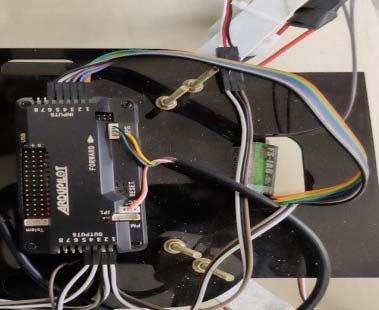
IVC RAISE 2020                                                                                                           IOP Publishing
IOP Conf. Series: Materials Science and Engineering              1055 (2021) 012006           doi:10.1088/1757-899X/1055/1/012006

      Detection of fire prone environment using Thermal Sensing
      Drone

                                        1*
                       N Nithyavathy ,S Arun Kumar2, D Rahul3, B Satheesh Kumar4, E R Shanthini5, C.Naveen6
                         1
                           Associate Professor, Mechatronics Engineering, Kongu Engineering College, Perundurai, India
                         2,6
                            Assistant Professor (Sr.G.), Mechatronics Engineering, Kongu Engineering College, Perundurai,
                         India
                         3,4,5
                               UG Scholar, Mechatronics Engineering, Kongu Engineering College, Perundurai, India
                         *E-mail: nithyavathy11@gmail.com

                         Abstract. Drones of various types are currently in great demand because of their flexible
                         applications to facilitate human life. At acceptable constant quality levels, they can perform tasks in
                         a repetitive manner. A drone is intended and built in the current work to evaluate the area
                         vulnerable to fire and its surface area at an altitude of 10 meters. In the event of a forest fire
                         disaster, evaluating the impacted area is very complicated. This approach needs to be adaptable and
                         easily controlled in order to solve it. Thus, both the manual and autopilot mode are built and
                         controlled by a quad copter drone with an ardupilot, which drives the drone to the specified
                         location. The drone is fed with the specification of the Global Positioning System ( GPS) and flies
                         with the aid of an ardupilot to the spot. With the aid of a thermal imaging sensor, the drone senses
                         the surface area with its captured image. With the aid of coding dumped in it, the image is sent to
                         the base station and the vision building is achieved with the help of the thermal camera fitted in the
                         front part of the drone and then it interacts with the base station where it is possible to view the
                         surface area. This allows average individuals to recognize the region impacted by the tragedy and
                         to predict the amount of impact they have made in a shorter period of time. Human interference is
                         minimized by this detection method in the areas affected by fire with the extent of fire prediction.

                         Keywords –Drone, Thermal Sensing, Fire Detection, Ardupilot

      1. Introduction
      No other technique is likely to be more critical for human durability, easement, and growth than the
      identification of fire accidents in rural forest areas.[1]Real-time data collected offers rapid intervention by
      the relevant services to prevent more destruction through natural calamities. Thus, under this rapidly
      adapting/ changing world, more studies on research like this could help to uncover/ discover the potential
      availability of technology for conservation. Like the timely fire appearance information decreases the
      number of areas threatened by this fire and thus minimizes the cost of extinguishing fires and the damage

              Content from this work may be used under the terms of the Creative Commons Attribution 3.0 licence. Any further distribution
              of this work must maintain attribution to the author(s) and the title of the work, journal citation and DOI.
Published under licence by IOP Publishing Ltd                          1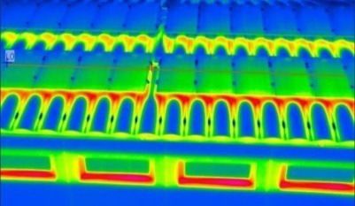
IVC RAISE 2020                                                                                           IOP Publishing
IOP Conf. Series: Materials Science and Engineering      1055 (2021) 012006         doi:10.1088/1757-899X/1055/1/012006

     caused by forests that are critical for protecting forests against fire. Organized human surveillance
     involves a large number of subjects, the monitoring of which would only cover the observation
     field.[2],[3]In forest-fire safety, automatic control and automatic early fire warning are definitely more
     advanced techniques. At a specific base, the duty operator uses infrared and TV cameras positioned at
     different locations and is able to monitor much wider spaces and to alert the approved services in an
     emergency. Such surveillance offers a good picture of the contours of the areas affected by flames, flame
     front lateral movement and other information that can be used to pick fire fighting tactics.[4] In addition to
     forest fire prevention approaches (observation, observation posts, patrols), several countries use an
     intelligent, automated framework for early detection and prediction of the spread of forest fires.[5]Early
     fire detection systems, as well as the necessary information about the location of the fire and its setting,
     are needed by fire departments. In this paper, a new method for early forest fire detection in field lands has
     been identified and assessed. This paper presents a model of forest fire detection based on terrestrial
     systems based on the required cameras, with the goal of providing a guide for the fire that spreads in the
     fields that can be monitored by the fire escort inside its home by providing only the field's GPS
     location.[6]

     2. Materials and Methods
     The components involved in the construction of the thermal sensing drone are shown in the Fig 1. The
     description for selecting the components is made as follows.

     2.1. Brushless DC motor
     In order to power the quadcopter, we need high-quality, powerful motors with rapid response. If one or
     more engines encounter some problems at some point during a flight, it will be catastrophic for the
     quadcopter, and could endanger the quadcopter itself at worst. In order to ensure a more stable flight, the
     engines are expected to provide a fast response. Ultimately, we need that the engines are close to vibration
     free. We agreed to acquire the Ready to Sky RS 2212-920kV Brushless Motor on the basis of these
     requirements shown in Fig 1.A. It is a brushless motor designed for both remotely operated and
     quadcopter airplanes and is considered to be highly reliable. Ready to Sky has long experience with RC
     aircraft and quadcopter engines, and their engines are proven to be vibration-free. According to the
     specifications, based on our ESC and propellers, each motor can give a thrust of 0.5 kg at 920 kilowatts.
     This is more than enough to satisfy our requirements, and if appropriate, we can perform fast movements,
     which will make the control sequence simpler.

                                      A. Brushless DC              B. GPS
                                     Motor                   Module

                                       C. Lipo Battery          D. Propeller with
                                                                     motor

                                                            2
IVC RAISE 2020                                                                                             IOP Publishing
IOP Conf. Series: Materials Science and Engineering      1055 (2021) 012006        doi:10.1088/1757-899X/1055/1/012006

                                        E. Ardupilot                F. Flysky

                                               G. Thermographic camera
                                    Figure1. Components in thermal sensing drone

     2.2.Thermal imaging camera
     A thermographic camera, referred to as an infrared camera or a thermal imaging camera or infrared
     thermography, is a device that uses infrared radiation to create a heat zone image, similar to a typical
     camera that uses visible light to form an image called a thermograph. A thermal imaging camera on a
     drone makes it a versatile instrument that can be used in many industries, including building, mining,
     energy, surveillance, firefighting, search and rescue. Thermal drones that use vision imaging cameras have
     so many beneficial uses by sensing heat that turns them into images and video from almost all objects and
     materials.

     2.3. Global positioning system Module(GPS)
     The pilot who is looking for lower-cost drones is always responsible for controlling every drone, using
     visual tracking to assess its location and orientation. Beginner drones typically have no GPS, but GPS
     receivers are used by more advanced drones shown in Fig 1.B. The following method is included in the
     navigation and control loop that makes some smart GPS drone navigation features[7-9].

     2.3.1. Position Hold:
     Enables the drone to retain its position at a set altitude and return home place. The drone recalls the
     location from which it took off, and it will automatically return to this location at the click of the return to
     home button.

     2.3.2. Autonomous Flight
     By creating GPS waypoints that identify the trajectory, the flight path of the drone can be predetermined.
     Then the drone will use the autopilot to navigate this direction upon execution. Both of these features
     include the use of a GPS drone system, so having a clear understanding of how GPS functions is important
     for a drone pilot. The global positioning system is a satellite navigation system that gathers signals from
     orbiting satellites using a radio receiver to determine location, velocity, and time. This navigation method
     is more precise than navigation types and offers knowledge of the location within a few metres. Within a
     few centimetres, advanced GPS systems can provide even greater accuracy. The miniaturisation of
     integrated circuits has made it possible for GPS receivers to be extremely inexpensive and open to
     everyone [10 - 13].

                                                             3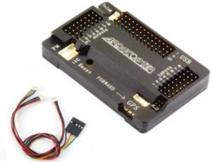
IVC RAISE 2020                                                                                          IOP Publishing
IOP Conf. Series: Materials Science and Engineering    1055 (2021) 012006       doi:10.1088/1757-899X/1055/1/012006

     2.3.3. Process involved in Autonomous Flight:
     GPS is a radio broadcasting device that covers almost every part of the world and is thus highly accessible.
     The global positioning system is a satellite navigation system that gathers signals from orbiting satellites
     using a radio receiver to determine location, velocity, and time. This navigation method is more precise
     than navigation types and offers knowledge of the location within a few metres. Within a few centimetres,
     advanced GPS systems can provide even greater accuracy. The miniaturisation of integrated circuits has
     made it possible for GPS receivers to be extremely inexpensive and open to everyone. GPS is a radio
     broadcasting device that covers almost every part of the world and is thus highly accessible.

     2.4.Raspberry
     A Raspberry Pi 3 (model b) is a computer with a single circuit. Raspberry Pi 3 (rPI3) offers rich support
     via a hardware and system software interface for interfacing external peripherals.[14] In this article, we
     will explore different configurations of hardware and system software available to the consumer through
     rPI3.

     2.4.1. Bus Addresses
     Registers for peripherals are available through their i/o address or bus address for the computer. At the
     0x7E00 _0000 address, peripherals are open. These addresses are greater than the physical address of the
     memory. In general, processors provide the IN/OUT op-code to access the peripherals. DMA control
     peripherals use bus addressing or direct addressing of devices.

     2.4.2. Physical Addresses
     A secondary cache, which is 1 GB on a rPI3, is physical memory. The physical memory of all peripheral
     bus addresses is mapped. Thus, in physical memory, accessing memory mapped addresses attempts to
     access the bus addresses. In bus addressing mode, this prevents the use of separate op codes. For RAM,
     physical addresses start at 0x00000000. The peripheral bus addresses are designed to map to a list of
     peripheral bus addresses beginning at 0x7E000000. Thus, at physical address 0x3Fnnnnnn, a peripheral
     advertised here at bus address 0x7Ennnnnnn is open. MMU maps the physical addresses of bus addresses.

     2.4.3. Virtual Addresses
     There are two aspects of a programme running: user mode and kernel mode. User programmes and kernel
     programmes do not use hard addresses to access physical memory; they use soft or virtual addresses
     instead. Usually, each programme runs on its own virtual address space, where the application code in the
     virtual address is lower than 3 GB, while the upper 1 GB (running on behalf of the user code) is occupied
     by the kernel code. A total of 4 GB adds up to 32 bit maximum addressing. This renders a real physical
     (RAM) memory size programme independent and all magic is performed via a page table of the mediator.

     2.5. Lipo Battery
     The motors and sensors for the quadcopter are all powered by a battery pack. We need a battery that stays
     within the microcontroller's input voltage limits, and that provides enough power for the battery to be able
     to support a flight for at least 10 minutes. We purchased the 4500mAh 3S 25C Lipo Pack supplied by the
     Hobby wing shown in Fig 1.C. This is a 4500mAh battery that should make it possible for us to have a
     regular flight for an estimated 15 minutes, while software needs to verify the battery voltage. The battery
     is very large-250 g and such a strong battery when selected. Four driver ESCs are used for controlling four
     motors, since each motor driver has two motor channels and each channel has the ability to control two dc
     motors. ESC's primary motive is to control the standardized peed across all motors, so that the motors can
     generate the same amount of thrust.

                                                           4
IVC RAISE 2020 IOP Publishing
IOP Conf. Series: Materials Science and Engineering 1055 (2021) 012006 doi:10.1088/1757-899X/1055/1/012006
2.6. Propeller Fins
The specifications are less rigid for the propellers than those for the engines. Light propellers with size and
lift potential are needed so that the quad copter can hover at less than 50% of the power of the motor. If
the propeller can withstand soft bumps, it is also preferable. We selected plastic 12X4.5 propellers
(304mmx114 mm) shown in Fig 1.D with their light weight for our quad copter. This is a traditional
propeller that many quad copters use. Although the pitch is 114 mm, the total length of the propeller is 12
inches.
2.7. Ardupilot
We discovered a fall during our project and calculated that a KK 2.1.5 board would not be adequate for
our purposes. So, for the transport of drugs, we need a control board that has high stability to lift a box
over a certain distance from the ground. We noticed during our development that the KK board lacked the
requisite stability to lift the weight and lacked autonomous flying as well. For this reason, in order to ease
development, we needed to upgrade to a more powerful board to enable potential improvements to make
the drone fly autonomously.[11] We compared the specifications of the KK board and the APM board,
and we can see that the APM shown in Fig 1.E has far superior specifications in terms of high stability,
number of digital i/o pins, GPS portability and wii navigation.
2.8. Fly sky Fs I6
The Fly Sky FS-i6 is a 2.4GHz device transmitter with a great entry level 6-channel telemetry that uses
powerful and efficient Automatic Frequency Hopping Digital System (AFHDS) spread spectrum
technology. While the programming is easy to use, the Fly Sky FS-i6 has both a good quality look and
feel.[10] In India, there are several Fly Sky FS-I6 ranges. 2.4GHz 6-Channel Radio Control System Set for
Optical Transmitter Receivers. Reliable-interference free application of the 2.4GHz AFHDS 2A signal.
Spectrum transmitters need receivers using DSMX or DSM2 algorithms. Less J's response is the most
reliable-this receiver only works with Fly Sky transmitters shown in Fig 1.F (using the AFHDS
algorithm).
2.9. Electric Speed Control
An electronic speed controller or ESC is an electronic circuit regulating and regulating an electric motor's
speed. It can also include motor reversal and dynamic braking. In electrically driven radio-controlled
versions, miniature electronic speed controls are used. There are also mechanisms in full-size electric
vehicles to control the speed of their drive motors. Brushed DC motors and brushless DC motors need
different types of speed controls. By varying the voltage on its armature, a brushed motor may have its
speed regulated. (Industrially, by changing the strength of the motor field current, motors with
electromagnet field windings instead of permanent magnets may also have their speed controlled.) A
brushless motor needs a different operating principle. The motor speed is varied by changing the timing of
the current pulses transmitted to the multiple motor windings.[15],[16].
3.Fabrication Process
3.1. Electrical Section
The electrical section consists of Ardupilot APM 2.8 circuit, raspberry pi3 module, Logitech 720p camera
and Lipo Battery. All the circuits are built using ardupilot default program. Based on the values from the
camera, the signals are fed to the raspberry pi3, which then converts these signals in the format required
for the actuating components which are propellers. The real time electrical circuit is shown in the figure 2.
The power source required for the operation of the motor is provided by the 11.1v and 4500Amph battery.
The motor are connected in parallel to the battery to maintain constant voltage and varying Current.
5IVC RAISE 2020 IOP Publishing
IOP Conf. Series: Materials Science and Engineering 1055 (2021) 012006 doi:10.1088/1757-899X/1055/1/012006
Figure 2. Electrical set-up Figure 3. Mechanical set-up
3.2. Mechanical Set-up
The mechanical portion consists of a frame or chassis that forms the basis of the prototype on which it is
possible to position the battery and electronic device. The mechanical section consists of a single frame
configuration with 4 aluminium rods and 4 plastic landing gears for safety landing purposes, to prevent
damage during landing to any part. To lift the entire setup, motors are used to produce heavy thrust.
Chosen 1000rpm/s motor, because the lifting process requires high speed. With the aid of a fixed nut, the
propellers are connected to the motor. The aluminium frame is used for weight control. At the bottom of
the chassis, a separate holder is built to house the camera. The aluminium frame, used to control the speed
of the propeller, is projected from the side of the chassis to carry the propeller and ESC module. In figure
3, the full mechanical setup is shown.
3.3. Fabrication Section
In fabrication usage of aluminum frame is to reduce weight, where GPS module, ardopilot, receiver,
camera, Electric Speed Control are supported. Interfacing the above components with raspberry pi3
module, results in the thermal detection in display which is captured by the thermal sensing drone[8] is
shown in the Fig 4.
Figure 4. Image captured by the Thermal sensing drone
4. Design Calculation
Thermal detection cameras consist of a sensor to detect infrared radiation that is emitted by the body. It
displays the temperature as a digital radiometric format image. There are two types of thermal cameras
such as thermal and photon detectors with tasks involved like (1) scanning device which allows capturing
a point/ line and (2) two-dimensional infrared focal plane array. This array allows capturing of different
elements of the captured image thus allows the detection of even slightest temperature variation in the
image.
The authors identified that the major factors considered for selection of payload details whether camera is
radiometric and comes with a gimbal. These identifications proved that the temperature readings added
with thermal imaging gives greater control to operator. The thermal sensing cameras operates in the mid-
wavelength infrared region of about 3–8 ȝm, with high thermal contrast. Also, atmospheric effects like
relative humidity, altitude and air density are avoided by making every measurement within the limit of 10
m with the target’s surface area.
6IVC RAISE 2020 IOP Publishing
IOP Conf. Series: Materials Science and Engineering 1055 (2021) 012006 doi:10.1088/1757-899X/1055/1/012006
4.1. Mass Calculation:
Weight Weight Weight
Component Component Component
(gm) (gm) (gm)
Frame 600 GPS module 17 Transmitter/receiver 392
Propeller 40 Ardupilot 43 Landing gear 200
Motor mass(4) 80 Camera 181 Lipo battery 270
ESC 10 Raspberry pi3 42 Weight of drone 1875
4.2.Thrust:
Total thrust = No. of motors x single motor thrust (g)
Total thrust = 4 x 1200 = 4800N
4.3.Thrust To Weight Ratio:
Ratio= Total thrust / Weight of Drone (N)
= 4800 / (18.39 x 9.81)
Ratio = 26.63
4.4.Average Amps Drawn:
AAD= AUW x P/V
= 1.875 x 170 /11.1
AAD = 28.71 amps
AUW = 1.875 kg
Power =170W/kg
Voltage =11.1 V
4.5. Flight Time:
Flight time =(Battery capacity x discharge) / AAD
=(4.5 x 0.8) / 28.71
Flight time =0.126 hours = 7.5 min
This proposed user interface system provides a mechanism forvideo information acquisition in the selected
region of interest, their input signal, smoothed signal, and their level of color variation.
This proposed system can determine and distinguish on the level of affect inforest fire prone areas.
5. Conclusion
The thermal sensing drone is designed to detect the fire prone/affected areas. The thermal cameras detect
all live beings whenever there is a thermal contrast between background data and foreground sensing. But
in this camera, there is a lack of sensing to specially detect the temperature of forest/trees. Thus a system
is proposed to detect temperature in the forest areas using ardupilot with the focus of color and depth of
data acquired from the acquisition sensors in the UAV. The ardupilot helps the drone to move to the
7IVC RAISE 2020 IOP Publishing
IOP Conf. Series: Materials Science and Engineering 1055 (2021) 012006 doi:10.1088/1757-899X/1055/1/012006
instructed location in the GPS and the camera sense the fire prone area and communicate it to the base
station with the help of program being dumped in raspberry pi3, so that base station will recognize the fire
prone areas and reduce the damage.
6. Future Scope
This drone can be further improved by incorporating Thermal camera for higher accuracy purpose.This
model can detect the fire prone area in night time only, so by incorporating the thermal camera we can
detect the fire prone area both in day and night time.
7. References
Santangeli, Andrea, Yuxuan Chen, Edward Kluen, Raviteja Chirumamilla, Juha Tiainen, and John
Loehr. "Integrating drone-borne thermal imaging with artificial intelligence to locate bird nests
on agricultural land." Scientific reports Volume- 10, Issue- 1 Jul.-2020; pp. 1-8,
doi.org/10.1038/s41598-020-67898-3.
[2] E. D. Kaplan, Understanding GPS: Principles and Applications, Artech House Publishers, ISBN
0890067937, February 1996.
[3] Ambrosia V, Hutt M, Lulla K (2011a) Special issue: Unmanned airborne systems (UAS) for remote
sensing applications. GeocartoInt 26(2):69–70
[4] Pooja Srivastava, TejaswiNinawe, ChitralPuthran, Vaishali Nirgude “Quadcopter for Rescue
Missions and Surveillance”, IOSR Journal of Computer Engineering (IOSR-JCE) e-ISSN: 2278-
0661,p-ISSN: 2278-8727 PP 48-52.
[5] , Reducing False Alarms in Vision-Based Fire
Detection,
! "#$%"&&'(('& ((&( ( )(*+&($ ,
6] Sravan Kumar N, Ram Kishore Sankaralingam, “Design And Control Implementation Of
Quadcopter”, International Journal of Mechanical And Production Engineering, ISSN: 2320-
2092, Volume- 4, Issue-5, May.-2016.
% Câmara, D. Cavalry to the rescue: Drones fleet to help rescuers operations over disasters scenarios. In
Proceedings of the 2014 IEEE Conference on Antenna Measurements & Applications (CAMA),
Antibes Juan-les-Pins, France, 16–19 November 2014; IEEE Publishing: San Antonio, TX,
USA, 2014; pp. 1–4.
[8] Joel Poncha Lemayian, “Autonomous First Response Drone-Based Smart Rescue System for Critical
Situation Management in Future Wireless Networks”, RS Open Journal on Innovation
Communication Technologies, published on May 2020.
[9] Md. Nafiz Hasan Khan, “Exploring Drones to Assist Firefighters During Emergencies”, 1st
International Workshop on Human-Drone Interaction, Ecole Nationale de l’Aviation Civile
[ENAC], May 2019, Glasgow, United Kingdom.
[10] J. A. Prakosa , “Speed Control of Brushless DC Motor for Quad Copter Drone Ground Test”,
, Saint Petersburg and Moscow, Russia, 2019, pp. 644-648, doi:
10.1109/EIConRus.2019.8656647.
[11] P.S. Mhetre, “Agriculture Drone For Fertilizer Spraying”, International Research Journal of
Modernization in Engineering Technology and Science Volume:02/Issue:06/June -2020
[12] Saroinsong, "Rancang Bangun Wahana Pesawat Tanpa Awak (Fixed Wing) Berbasis
Ardupilot." Journal Teknik Elektro Dan Komputer 7, no. 1 (2018): 73-84.
[13] C. Yuan "UAV-based forest fire detection and tracking using image processing techniques", 2015
International Conference on Unmanned Aircraft Systems (ICUAS), Denver, CO, 2015, pp. 639-
643, doi: 10.1109/ICUAS.2015.7152345.
[14] Yuan "A survey on technologies for automatic forest fire monitoring, detection, and fighting using
unmanned aerial vehicles and remote sensing techniques", Canadian journal of forest
research 45.7 (2015): 783-792.
8IVC RAISE 2020 IOP Publishing
IOP Conf. Series: Materials Science and Engineering 1055 (2021) 012006 doi:10.1088/1757-899X/1055/1/012006
[15] Liyang, "Real-time forest fire detection with wireless sensor networks", Proceedings. 2005
International Conference on Wireless Communications, Networking and Mobile Computing,
2005.. Vol. 2. IEEE, 2005.
[16] Westerlund, "Drone hacking with raspberry-pi 3 and wifi pineapple: Security and privacy threats for
the internet-of-things", 2019 1st International Conference on Unmanned Vehicle Systems-Oman
(UVS). IEEE, 2019.
[17] N. Nithyavathy, S. Pavithra, M. Naveen, B. Logesh, T. James, “Design and Development of Drone
For Healthcare”, International Journal of Scientific & Technology Research, ISSN: 2277-8616,
Volume- 9, Issue-1, Jan.-2020.
9You can also read