Development and Performance Evaluation of a Dead Weight Force Machine in 2-50N Range
←
→
Page content transcription
If your browser does not render page correctly, please read the page content below
MAPANDevelopment    and Performance
      - Journal of Metrology Society ofEvaluation
                                        India, Vol. of
                                                    24,a Dead
                                                         No.4, Weight
                                                               2009; pp.Force Machine in 2-50N Range
                                                                         225-232
ORIGINAL ARTICLE

           Development and Performance Evaluation of a
            Dead Weight Force Machine in 2-50N Range

               S.S.K. TITUS1*, S.K. DHULKHE2, POONAM YADAV1 and KAMLESH K. JAIN1
              1
               National Physical Laboratory (NPLI), Council of Scientific and Industrial Research (CSIR)
                                             New Delhi - 100 012, India
                 2
                   Department of Mechanical Engineering, SDM College of Engineering & Technology
                                               Dharward, Karnataka
                                        *e-mail: titus@mail.nplindia.ernet.in

                              [Received: 15.04.2009 ; Revised: 27.08.2009 ; Accepted: 29.08.2009]

                                                          Abstract
         Results of the performance evaluation of a newly designed, developed and fabricated dead weight
         machines to realize forces in the range of (2-50) N are reported in this paper. Precision load cells of 20N,
         50N and 100N having an expanded uncertainty of ± 0.03% are used for this evaluation. The calibration
         of these load cells against the dead weight force machine shows that the repeatability (Rep) and
         reproducibility (Repr) are better than 0.003% and 0.005% respectively, over the entire range. The
         calibration data observed is found to closely agree with the calibration results obtained directly against
         the Physikalsich-Technische Bundesanstalt (PTB), Germany force standard machine having the relative
         measurement uncertainty of the force scale in the measuring range ≤ 0.002%.

1.   Introduction                                                upgrade the existing standards and establish new
                                                                 standards [9] in upcoming areas traceable to System
     The fast pace of industrial development due to              International (SI) units to improve the entire hierarchy
scientific and technological advancement demand a                of measurement system and to provide traceability to
better quality of measurement system to come into                the users.
place for consistently improving the quality of the
products manufactured and to remain globally                          Recently, there has been a great demand to realize
competitive. National Metrological Institutes (NMIs)             force in sub newton range, traceable to SI units. The
around the world are faced with the challenge of                 use of instruments such as atomic force microscope,
devising [1-4] appropriate method and procedures to              coordinate measuring machine, stylus system,
disseminate SI units without much degradation in                 hardness        measuring          devices,      micro-
uncertainty during the process and to innovate                   electromechanical system (MEMS) have been
technique/ standards to provide national traceability            significantly seen increased use in the recent past to
in emerging areas [5-10] to the shop floor level                 characterize newly developed materials for
economically and efficiently. National Physical                  understanding their properties better, for potential
Laboratory (NMI of India) endeavours continuously                industrial applications. In all these techniques, a small
to carry out research and developmental activities to            load is exerted on the object during the measurement
                                                                 by a sensing probe. It is mandatory, as per quality
© Metrology Society of India, All rights reserved.

                                                                                                                        225
S.S.K. Titus, S.K. Dhulkhed, Poonam Yadav and Kamlesh K. Jain
management system ISO 17025-2005, to know the capacity in the full range from (2-50) N with particular
uncertainty associated with such measurements made reference to repeatability, reproducibility, parasitic
and hence, the calibration of these forces are essential components, etc. and these results are presented here.
against the established standard of lower uncertainty Further, the closeness observed in the relative errors
linked to SI units. These forces are presently estimated of repeatability and reproducibility of the load cells,
both theoretically as well as experimentally with an 50N and 100N, calibrated directly against a force
uncertainty of a few percent. This necessitates the NMI standard machine maintained at PTB, Germany and
to create, establish and maintain standards in this subsequently on the machine under consideration add
range [5-7] and disseminate, as per the emerging need confidence to the precision achieved in the fabrication
of the industries, in order to maintain the uniformity of the machine and reaffirms the performance of the
in the force measurements with lower uncertainty. machine. This machine is interfaced with a computer
and all its operations are controlled through a menu
The most reliable method to realize forces in SI
driven software to use the machine in fully automated
unit with lower uncertainty is through direct
mode [11]. A brief account of the technique used for
application of the calibrated dead weights under
its automation is also mentioned here.
known gravitational field. To the best of our
knowledge there is no reliable and direct method 2. Description of the Machine
available at present to realize force lower than 5 N,
which corresponds to a precise calibrated mass of 500 The dead weight force machine (Fig. 1) consists
gm. To realize the force of 10 μN one needs to have a of a loading hanger and sets of dead weights to
calibrated mass artifact of 1mg which is the lowest generate the desired force steps. Two vertical columns
mass that can be handled manually. However, the are employed to support several horizontal platens
relative decremented size of the mass hampers the on which the channels having the dead weights are
overall uncertainty associated with the force made to rest. The horizontal platen, which houses the
measurements in the sub-newton level. In order to load cell is connected through a lead screw for suitably
overcome this limitation, attempts have been made to adjusting the height of the load cell under calibration
measure [5-7] the small forces in the range of mN-μN
using force compensating and in even lower ranges
using electro static force balances [10], which are
either at the developmental stage or beginning to come
into operation. Further, to fulfill the requirement of
traceability of these measurements to SI unit, a force
calibrating machine based on the first principle is
designed, developed and fabricated to realize static
forces in the range of (2-50) N.
The aim of developing this machine is primarily
to provide SI traceability in the low range of force
measurements. Also, as few of the force steps of the
machine overlaps with the already established force
standard machine, available with the group whose
Calibration and Measurement Capabilities (CMC) are
listed in the appendix 'C' of Bureau International des
Poids et Measures (BIPM) website (www:BIPM.org),
it will be an added advantage to affirm the uncertainty
value associated with the force realized by the
presently developed machine.
Performance evaluation of the machine has been
carried out using precision load cells of suitable Fig. 1. Dead weight force machine (2N-50N)
226Development and Performance Evaluation of a Dead Weight Force Machine in 2-50N Range
in compression mode. The compression pads, which calibration as per any one of the standard procedures
are used to sandwich the load cell between the upper ASTM E-74-2006, ISO 376-2004 or IS 4169-1988 [12].
beam of the loading hanger and the resting platen are A minimum force of 2 N, which is the nominal load of
grounded to an average surface roughness of 0.2 the calibrated loading hanger made out of titanium,
micron. Provision was there to rotate the load cell along is always included as the first applied force and it
its axis for taking observations at three different represents the minimum force that can be realized with
positions as per the requirement of calibration the machine. The weight stack consists of masses
standard procedure [12]. A pneumatic system made of aluminum and stainless steel adjusted to
equipped with solenoid valves is used to load and nominal force value of 0.5 N, 1 N, 2 N & 5 N with an
unload the dead weights smoothly. The load cell expanded uncertainty of ± 0.0002% by NPL mass
supports the upper beam of hanger and the lower end standard group. The 10 N, 20 N & 50 N capacity load
of which is directly connected to the weight stack. cells can be calibrated using the force calibrating
machine just by changing the mass set. The load can
Desired force step can be generated by applying be applied or removed within a predetermined time
the load through the loading hanger and the selected with negligible oscillations and vibrations ensuring
weight from the weight stack. The weight applied to better stability and repeatability.
the load cell is the sum of the weight selected, plus the
Deflection and stress distribution studies of the
weight of the loading hanger. The design of the
loading hanger of titanium was carried out as depicted
machine is such that any weight can be loaded and
in Fig. 2, using UG-NX2 software for modeling and
unloaded irrespective of its position in the weight stack.
Femap-Nastran for analysis. It is found that the total
The channels could be lifted or lowered in a controlled
deflection of the loading hanger beam is found to be
manner for engaging the weights to the loading hanger. 0.0025 μm which is well below the accepted limits of
A central vertical rod, with a seating arrangement for (6.5 μm) deformation confirming a good mechanical
individual dead weight is joined together, runs through stability of the loading hanger in the range it is used here.
all the horizontal plates to engage the selected weights
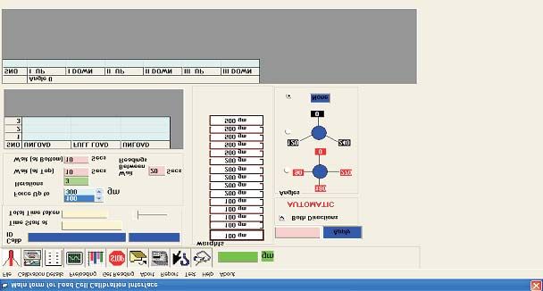
which in turn is connected on to the loading hanger. A PC based software [11] enables the operator to
The distribution of the mass to the upper and the lower select through a menu driven window (Fig. 3)
part is such that the center of gravity of the loading software, a predetermined duration time between two
hanger is situated below the load cell. subsequent measurements and a waiting time after
the full load and at unload position before the start of
Once the load cell is appropriately placed to carry next cycle. The software connected through Embedded
out the calibration, it is possible to carry out the Server to a relay unit actuates a particular valve to
Fig. 2. Deflection analysis of the loading hanger
227S.S.K. Titus, S.K. Dhulkhed, Poonam Yadav and Kamlesh K. Jain
Fig. 3. The menu driven software used for operating the machine
apply the selected load to the load cell and the of the machine, Δg is the variation of the g along the
indicator reading is recorded in the excel format after height of the machine, ρa , ρm are the densities of air
the predetermined time selected on the menu at the and of the material of the masses, respectively. It is
start up. evident from Eq. (1) that the overall uncertainty in the
force realized by the dead weight force machine at a
The interaction of Embedded server with PC is particular location depends upon the uncertainty of
through RS232c PORT. The other end outputs different the individual parameters of Eq. (1). The term Δg in
Network buses to connect devices such as Relay Unit the above equation can be neglected as the variation
and Indicator. The front end software to control the of g from its bottom to the top of the loading stack is
load cell calibration is a GUI-based user-friendly less than a ppm. Taking the other variants from Eq.
software with on line help facility. It has various (1), the values of the differentials and their
parameters like wait time definitions, angles uncertainties, the estimated uncertainty of the dead
definitions and facilities for reporting the results. The weight force calibrating machine is ± 0.00055 % (k=2)
software consists of a database for storing the as listed in Tables 1&2. However, this theoretically
observations made at different loads, angle positions estimated value would not be true in reality due to
and the time interval maintained during the various factors, like the interaction between the
calibration for generating calibration reports. The machine and the load cell, the force parasitic
software has a in-built facility to incorporate the components of the force calibrating machine, the
environmental conditions and to evaluate the measurement procedure with particular reference to
uncertainty of measurement as per the GUM document creep and creep recovery, etc., contributing a finite
[13] and to carry out the classification as per the written value to the estimated total uncertainty associated
international standards. with the force realized by the machine. Considering
3. Results and Discussion all these different influencing input quantities and
following the discussion and suggestion made by
3.1 Estimation of Uncertainty of Dead Weight Force Sawla [14] elsewhere, an expanded uncertainty of the
Calibrating Machine vertical components of force applied over the whole
range of the dead weight force calibrating machine
In SI units the vertical force exerted by a stationary on conservative basis is presumed to be better than ±
mass in dead weight force machine in air on its 0.005%.
support is given by:
3.2 Performance Evaluation of the Dead Weight Force
F = (g-Δg) m (1- ρa /ρm) Calibrating Machine
where, 'F' is in Newton (N), 'm' is the mass in kilogram In order to reaffirm the uncertainty associated
(kg), 'g' is the local gravity measured near the bottom with the force realized by the machine three precision
228Development and Performance Evaluation of a Dead Weight Force Machine in 2-50N Range
Table 1
Measurement uncertainty of 2N force realized by the machine
Parameter Value Parameter Distribution Standard Sensitivity Uncertainty Square of
Uncertainty factor Uncertainty Coefficient contribution Uncertainty
(N) contribution
m (kg) 0.204294 1.00E-06 Normal, 2 5.00E-07 9.79E+00 4.89E-06 2.40E-11
g (m/s2 ) 9.791233 9.79E-06 Normal, 1 9.79E-06 2.04E-01 2.00E-06 4.00E-12
ρa (kg/m3 ) 1.150 3.45E-03 Rectangle, 1.732 1.99E-03 -2.52E-04 -5.01E-07 2.51E-13
ρm (kg/m3 ) 7950.00 7.00E+01 Normal, 2 3.50E+01 3.64E-08 1.27E-06 1.62E-12
Force (N) 2.0000008
Combined uncertainty (N) 5.459E-06
Expanded uncertainty (N) 1.09E-05
Relative Expanded uncertainty (%) 5.46E-04
Table 2
Measurement uncertainty of 50N force realized by the machine
Parameter Value Parameter Distribution Standard Sensitivity Uncertainty Square of
Uncertainty factor Uncertainty Coefficient contribution Uncertainty
(N) contribution
m (kg) 5.107356 2.50E-05 Normal, 2 1.25E-05 9.79E+00 1.22E-04 1.50E-08
g (m/s2 ) 9.791233 9.79E-06 Normal, 1 9.79E-06 5.11E+00 5.00E-05 2.50E-09
ρa(kg/m3 ) 1.150 3.45E-03 Rectangle, 1.732 1.99E-03 -6.29E-03 -1.25E-05 1.57E-10
ρm (kg/m3 ) 7950.00 7.00E+01 Normal, 2 3.50E+01 9.10E-07 3.18E-05 1.01E-09
Force (N) 50.000078
Combined uncertainty (N) 1.364E-04
Expanded uncertainty (N) 2.73E-04
Relative Expanded uncertainty (%) 5.46E-04
load cells (20N of M/s Sushma Industries and 50N 40, HBM, Germany) having a resolution of 1 × 10⁻⁶
& 100N of 1HBM, Germany) were calibrated on the and a stability of 5 × 10⁻⁶ was connected to a PC through
machine under suitable environmental conditions GPIB interface using software. The load cell chosen
following the calibration procedure [15] NPL-02 C for calibration was placed on the machine and the
based on ISO 376 - 2004 and IS 4169:1998. The 50N & indicator was switched on for sufficient time before
100N load cells2 were also calibrated directly against starting the calibration for attaining better temperature
the force standard machine of PTB, Germany under stability. The load was transmitted through a self
the similar conditions following the same procedure. aligning compression pads supplied by the
For minimizing the uncertainty associated with the manufacturers. An uniform time interval was
indicating instrument, a digital indicator (Model DMP maintained while taking the measurements at each
force step to minimize the uncertainty of the mean
1
The commercial equipments mentioned in this paper are only
for identification and better understanding. It does not imply
values due to the influence of the loading process and
recommendation or endorsement by NPL, India nor does it the creep pattern of the load cell.
imply that the equipments mentioned are the best available for
this purpose. In all calibration, preliminary loading at 0º
2
The calibration mark for 50N force transducer is 0519 PTB 08 position was performed three times to the maximum
dt. 01.08.2008 and the calibration mark for 100N force trans- capacity of the machine or the load cell-which ever is
ducer is 0510 PTB 08 dt. 01.08.2008. As we were not having lower and kept for 90 seconds before returning to zero.
the 20N load cell with us at the time of calibrating the other
two load cells at PTB, Germany, the PTB calibration data for When the load cell was rearranged to new positions
20N load cell is unavailable for comparison. at 120º and 240º, it was preloaded only once. All the
229S.S.K. Titus, S.K. Dhulkhed, Poonam Yadav and Kamlesh K. Jain
measurements were made following a uniform loading two cases of 20N and 100N load cells observations
sequence to minimize the load time effect. After were made following the same calibration procedure
waiting for 90 seconds, on returning to zero, another at ten different force steps. As such 58 (64 in case of
force series was started and the same procedure was 20N load cell) observations were taken to complete
repeated at every new position of the load cell to record the calibration of each load cell.
the observations in ascending or in descending order
or in both the directions as the case may be. Figures (4-6) show the repeatability and
reproducibility of the calibrated load cells on this
Six series of force measurements were carried out machine. A repeatability within 0.003% and a
in all the calibrations performed for each load cell. reproducibility within 0.005%, observed from the
The 50N load cell was calibrated at 0º position by calibration of these precision load cells directly against
taking two series of forces in ascending order at force the dead weight force machine, in the optimum range
values 5, 10, 15, 20, 25, 30, 35, 40, 45 and 50N. Further, (20% to 100%) of their capacities, show the reliability
at 120º and 240º positions, the load cell was calibrated and the performance of the developed machine. In
by applying two series of forces at each position, that comparison exercises, it is mandatory to compare the
is one series in ascending order from (5-50) N and mean force values as observed at the two different
other series in descending order from (50-5) N, at all participating laboratories/ NMIs to establish the
the force steps mentioned above. Similarly, in the other degree of equivalence of standards belonging to the
Fig. 4. Relative repeatability and reproducibility errors of 20 N load cell
Fig. 5. Relative repeatability and reproducibility errors of 50 N load cell
230Development and Performance Evaluation of a Dead Weight Force Machine in 2-50N Range
Fig. 6. Relative repeatability and reproducibility errors of 100 N load cell
two laboratories. However, at this moment our focus about the stability and the parasitic components of
is not to establish the degree of equivalence of the machine. Keeping this in view, the good closeness
standards but to gain confidence in the performance of the data observed at PTB, Germany and NPLI, the
of the calibrating machine so developed. This can be data observed with the 20N load cell at NPLI is also
judged by comparing the repeatability and included in Table 3 which generate confidence about
reproducibility of the observation taken using the same the behaviour of the machine throughout the range of
load cells under similar condition following the same force realized. However, the higher relative errors
calibration procedure at NPLI and PTB, Germany. observed in the measurements using 20N load cell
below its 20% capacity may perhaps due to the
The repeatability and reproducibility data characteristics behaviour of the 20N load cell at the
observed from the calibration of 50N and 100N load
lower end.
cells is listed in Table 3. As the variation of the
repeatability and reproducibility is between 0.003% 4. Conclusion
to 0% and 0.006% to 0.002% respectively, irrespective
of the data taken with any of the two load cells from A 50N reliable low cost fully automated dead
NPLI or PTB, Germany, this builds up the confidence weight force machine for calibrating load cells of 10N,
Table 3
A comparative table showing the relative errors obtained with the load cells
50N HBM load cell 100N HBM load cell 20N load cell
Force *PTB, Germany NPLI *PTB, Germany NPLI NPLI
N Rep % Repr % Rep % Repr % Rep % Repr % Rep % Repr % Rep % Repr %
5 0.001 0.001 0.003 0.005 0.003 0.005
10 0.001 0.001 0.003 0.004 0.002 0.000 0.003 0.005 0.002 0.003
15 0.001 0.002 0.003 0.005 0.001 0.002
20 0.001 0.000 0.002 0.003 0.001 0.003 0.003 0.005 0.001 0.002
25 0.001 0.000 0.002 0.003
30 0.001 0.000 0.001 0.003 0.001 0.006 0.001 0.003
35 0.001 0.001 0.000 0.002
40 0.001 0.001 0.001 0.003 0.001 0.005 0.001 0.002
45 0.001 0.001 0.000 0.003
50 0.001 0.001 0.000 0.003 0.000 0.004 0.000 0.003
231S.S.K. Titus, S.K. Dhulkhed, Poonam Yadav and Kamlesh K. Jain
20N and 50N capacities in compression mode has [6] Jens Illemann, The Achievable Uncertainty for
been developed and established following any one Balance-Based Force Standard Machines in the
of the internationally recognized calibration Range from Micro Newton to Newton, IMEKO
procedures to the highest possible accuracy class. 20th TC3, 3rd TC16 and 1st TC22 Merida,
Mexico (2007).
The closeness observed in the repeatability and
reproducibility data between the direct calibration of [7] Vladimir Nesterov, Facility and Methods for the
the 50N and 100N load cells against the dead weight Measurement of Micro and Nano Forces in the
force calibrating machines of the two laboratories Range below 10-5 N with a Resolution of 10-12
NPLI and PTB, Germany generates confidence in the N (Development Concept), Meas Sci.Tech, 18
precision achieved in the fabrication of the machine, (2007) 360-366.
as regard to the stability, parasitic components, and [8] Toshiyuki Hayashi, Yoshihisa Katase,
hence the derived uncertainty of ± 0.005 % throughout Kazunaga Ueda,Tsuyoshi Hoshino, Hiroshi
the range associated with the applied forces. Suzawa and Masaaki Kobayashi, Performance
of Force Comparator with Reference to Tuning-
Acknowledgement Fork Type Force Transducer, IMEKO 20th TC3,
3rd TC16 and 1st TC22, Merida, Mexico (2007).
The authors are grateful to Prof. Vikram Kumar,
Director, National Physical Laboratory for [9] Kamlesh K. Jain, S.S.K. Titus, Harish Kumar and
permission to publish the work. The authors are also H.N.P. Poddar, An Automated Dead Weight
thankful to Dr. S.K. Jain, Head, Force and Hardness System for Realizing Force in 1 N-10 N Range,
Standard, NPLI for his valuable suggestions. NCSL International Conference, Orlando,USA
(2008).
References [10] P.J. Pratt, Measurement of Nano - Pico Newton
[1] Richard A. Mitchell, Force Calibration at the Forces Using Electrostatic Balance, IMEKO 18th
National Bureau of Standards, NBS Technical TC-3, Proceedings, "Force, Mass, Torque and
Note, 1227 (1986) 1-21. Pressure", Celle, Germany (2002).
[2] Toru Aoki, Iwao Maekawa and Hideo Shinji, [11] Harish Kumar, S.S.K. Titus and Kamlesh K. Jain,
Structure and Performance of Newly Automation of the Dead Weight Force Machine,
Developed 10MN Hydraulic Force Private Publication (2009).
Calibration Machine", IMEKO 16th TC-3 [12] Calibration of Force - Proving Instruments Used
Proceedings, Force, Mass and Torque, Taejon, for the Verification of Uniaxial Testing
South Korea (1998). Machines, ISO 376-2004; Standard Practice of
[3] Sinan Fank, Amritlal Sawla and Hakan O. Calibration of Force - Measuring Instruments
Ozbay, Long Term Observation of Newly for Verifying the Force Indication of Testing
Developed 110 kN /1.1 MN Lever Machine, ASTM E-74 (2006).
Amplification Dead Weight Force Standard [13] Guide to the expression of Uncertainty in
Machine at UME, IMEKO XIV World Congress Measurement, ISBN 92-67-10888-9 International
Proceedings, Finland, 3 (1997) 7-12. Organization for Standardization, 1993;
[4] Kamlesh K. Jain, H.N.P. Poddar and M.K. Uncertainty of Calibration Results in Force
Chaudhauri, Establishment of a 10 kN Dead Measurements, EA-10/04 (EAL - G22)( 1996).
Weight Force Standard Machine at NPL (India), [14] Amrit Lal Sawla, Uncertainty Scope of the Force
IMEKO 18th TC-3, Proceedings " Force, Mass, Calibration Machine, IMEKO XVI World
Torque and Pressure", Celle, Germany (2002). Congress Proceedings, Vienna, Austria, 3 (2000)
[5] S. Niehe, New Experience with a Force 253 - 258.
Measuring Facility from the Range from 1mN [15] Monograph, Calibration Procedure for Force &
to 5N, IMEKO 19th TC3, Proceeding "Force, Torque Transducer, National Physical
Mass and Torque", Cairo (2005). Laboartory, India (2004).
232You can also read