Development of Different Disc Brake Rotor Designs - IEOM ...
←
→
Page content transcription
If your browser does not render page correctly, please read the page content below
Proceedings of the 11th Annual International Conference on Industrial Engineering and Operations Management
Singapore, March 7-11, 2021

         Development of Different Disc Brake Rotor Designs
                                        Stephen Da Silva
                   Department of Mechanical and Industrial Engineering Technology
                                    University of Johannesburg
                                    Johannesburg, South Africa
                                     sdasilva23@hotmail.com

                                    Daramy Vandi Von Kallon
                   Department of Mechanical and Industrial Engineering Technology
                                    University of Johannesburg
                                    Johannesburg, South Africa
                                         dkallon@uj.ac.za

                                                       Abstract
Brakes are compulsory systems that are used to slow a vehicle’s speed down or used to bring a vehicle to a complete
halt. The aim of this report is to determine if increasing the ventilation in a combination disc brake rotor, will make it
more durable than the grooved disc brake rotor due to increased heat dissipation or render it weaker. Observations of
the simulations obtained identified that the disc rotors experienced different stress concentrations and displacements.
The inner filleted race below the rotor hat on both disc designs had the greatest values of stress recorded. The grooved
disc brake experienced a maximum stress of 56.043MPa and the combination disc brake experienced a maximum
stress of 62.371MPa with the largest exerted load of 35KN. The grooved disc brake experienced a maximum
temperature of 1216.oC and a maximum heat flux of 1.5042 x 10⁶ W/m2. The combination disc brake experienced a
maximum temperature of 1067.1 oC and a total heat flux of 1.3548 x 10⁶ W/m2. The combination of drilled and
grooved may have experienced slightly higher stress values but e lower temperature readings under a load and is
considered the better design.

                    Keywords: Brakes, Grooved, Drilled, Stress, Thermal, Disc, Temperature

1. Introduction
Brakes are one of the most important and crucial safety components used in all modern vehicles. Brakes are
compulsory systems that are used to slow a vehicle’s speed down or used to bring a vehicle to a complete halt. These
components function to slow and stop the rotation of a wheel bringing the speed of the vehicle down to the drivers
desired range. This task is completed mechanically when the braking pads are forced and inserted against the rotor
disc on both surfaces of the wheel allowing the vehicle to slow down. This produces a retarding action against the
movement of the vehicle (Manjunath & Suresh, 2013; Reyes, et al., 2019). In the present paper, a grooved-disc brake
rotor and a combination drilled-grooved brake rotor are designed using a design software Autodesk Inventor, and a
simulation of static stresses and thermal analysis are performed using the static and thermal stress analysis
environment of the ANSYS software. Identifying critical zones affected by the static and thermal stresses on the brake
discs after the results of the simulation have been obtained.

2. Conceptual Design of Both Brake Discs
The conceptual design was based on a standard Brembo disc brake rotor used on Renault vehicles. The disc brake
design has a minimum thickness of 4.95mm on the mounting face and a mass of 5kg. The same design was used for
the grooved and combination drilled and grooved disc brake. The designs were completed to improve on a solid brake
design to handle different static loads ranging from 20KN, 23KN, 26KN, 29KN, 32KN, 35KN while maintaining
minimal deformation and effective heat dissipation. These designs include a circular rotor hat of 152mm and a circular

                                           © IEOM Society International                                             7015
Proceedings of the 11th Annual International Conference on Industrial Engineering and Operations Management
Singapore, March 7-11, 2021
disc. The apertures of the holes on the hub are based on the receiving wheel mounting lugs. The bolt circle is positioned
around the estimated circle on the hub of the disc. Modern day vehicles receive a 4 or 6-hole pattern, however, a 4-
hole pattern will also be sufficient and used. The disc consists of two single plates of 258mm diameter. The disc plates
are separated by a range of vanes with a height of 19.65mm. These vanes are used as a ventilation system to allow
heat to dissipate while the disc rotor is in operation from friction contact with the brake pad. The surface of the first
disc brake has groove features located on the outer edge of the inboard plate travelling inwards to the centre before
the hat of the rotor. While the second design has both grooves and drilled holes located on the outer edge of the inboard
plate traveling inwards to the centre before the hat of the rotor. These holes are drilled in a similar pattern next to the
machines grooves without overlapping each other (Da Silva & D.V.V, 2019).
2.1 Design Concept for the Grooves on the Groove Brake Disc Rotor
The grooves located on the surface of the plate may be formed using a repeated pattern of equally spaced grooves
rotated around the disc. The grooves may overlap and may have various shapes and different designs, but the same
shape must be used when the first groove is made. The arrangement of grooves on the surface of the brake disc
increases friction between a brake rotor and brake pad allowing for better grip on the two surfaces. During heavy and
repeated braking, thermal temperatures are increased on the rotor due to friction. The increased temperatures caused
by friction creates a layer of gas, dust and heat between the pad and the rotor. The grooved surface of the rotor allows
the built-up gas and heat to escape through the grooves. During heavy and repeated braking, thermal temperatures are
increased on the rotor due to friction. The increased temperatures caused by friction creates a layer of gas, dust and
heat between the pad and the rotor. This allows the built-up gas and heat to escape through the grooves (Deekshith, et
al., 2017; Grzes, et al., 2016).
The depth of the groove is measured from the outer edge moving towards the rotor hat. The depths ranges preferably
from about 2mm to 10mm. Where 2.5mm to 7mm is considered good and 3mm to 6mm is considered the best size to
machine the grooves. Grooves should not be too deep as it may cause material fatigue and weaken the overall strength
of the brake disc. The width measurements of the grooves should preferably be at about 1mm to 7mm or better at
1.25mm to 5mm or the best range between 1.5mm to 4mm wide. The width is dependent on the overall diameter of
the disc plate ( (Deekshith, et al., 2017).
2.2 Design Concept for the Drilled Holes and Grooves for a Combination Disc Brake Rotor
The drilled holes are located on the surface of the rotor plate and are drilled through the inboard and outboard friction
plates. The holes are drilled using a repeated and symmetrical pattern of equally spaced holes rotated around the disc,
that may follow the same pattern as the grooves in combination disc brakes. The holes can be drilled adjacent to the
machined grooves on the disc brake in combination designs. Cross drilled holes shorten the stopping distance of a
vehicle for a given brake pressure and greatly reduces the brake disc temperature. The cooling performance of a disc
brake is greatly increased when cross drilled compared to standard solid brakes. The number of holes drilled may vary
between 3-5 holes per row. The holes must have an identical diameter to the first hole drilled to allow even cooling
efficiency throughout the brake disc and prevent any build of heat or gas within any section of the rotor that may lead
to brake fade and thermal cracking (Patel, et al., 2016).
The hole diameter may vary between 3mm to 12mm although the most effective range of diameters are between 5-
8mm. The number of holes on any disc brake are dependent on the design and varies between 15- 126 holes. Drilling
holes on a disc brake must be performed preciously as drilling too many holes weakens the material integrity of the
disc brake rotor. When there are too many holes or if the diameter of the holes is too great it may lead to premature
brake failure if heavy braking is required. All drilling must be arranged in an inline pattern along the radial direction
as each hole must be located at the centre of each cooling passage between two neighboring vanes to maintain the
disc’s strength and material integrity (Limpret, 2011; Malott & Lou, 2009).
2.3 Design Variables
• Groove patterns may be different shapes.
• Groove thickness and width should be between 3mm to 6mm groove depth and 1.5mm to 4mm wide.
• Drilled holes should be between5-8mm diameter.
• Drilled holes may vary between 15-126 holes.
• Grey Cast iron is the best material choice for the grooved-disc brake rotor and drilled and grooved disc brake
rotor due to its good thermal and mechanical properties.
© IEOM Society International 7016Proceedings of the 11th Annual International Conference on Industrial Engineering and Operations Management
Singapore, March 7-11, 2021
• 5-hole pattern or 4-hole pattern may be used on the hat surface dependent on the wheel.
• Fillets used in the design to decrease stress concentrations to allow the disc brake rotor to be more durable
and capable of handling larger loads.
2.4 Design Restrictions
• Grooves must be a repeated pattern of equally spaced grooves rotated around the disc symmetrically.
• Grooves and drilled must travel 360° around the friction surface while not overlapping each other.
• All drilling must be arranged in an inline pattern along the radial direction as each hole must be located at
the centre of each cooling passage between two neighbouring vanes to maintain the disc’s strength and
material integrity.
• Disc rotor must be ventilated with vanes between two plates for best efficiency.
• The brake disc must be light in mass.
3. Materials Selection
The materials used for manufacturing the grooved disc brake rotor and the drilled and grooved disc brake rotor is grey
cast iron. Grey cast iron has a high thermal conductivity, high thermal diffusivity, good vibration damping capabilities
at a low cost. Cast iron is relatively low-priced and can be easily cast into complex shapes. The high thermal diffusivity
and thermal conductivity is crucial for a brake design as the brake experiences high temperatures and abrasion due to
contact friction in slowing a vehicle down. Grey cast iron is used typically as a standard for the manufacturing of
brake disc in modern vehicles (Manjunath & Suresh, 2013).
The metallurgical properties of grey cast iron determine characteristics of the brake disc such as strength, noise and
durability. If a brake disc is too soft, it will wear quickly and if it is too hard it will easily crack [6]. Grey Cast iron
consists of two main substances: carbon flakes and matrix ferrous metals. These substances have substantial influence
on the stress-strain responses of the material. Weak bonding between the graphite flakes and metal matrix cause gaps
and voids when the material is put under a load. However, the compressive strength of grey cast iron is three times
higher than its tensile strength. The compressive strength ranges from 570-1290MPa and tensile strength of 98-
280MPa (Qian, et al., 2001; Sanaka & Kumar, 2015).
The mechanical Properties of Grey Cat Iron are
• Ultimate Tensile Strength 115-700MPa
• Yield Tensile Strength 65.5-172MPa
• Compressive Yield Strength 572-1380MPa
• Modulus of Elasticity 62.1-162GPa
• Brinell Hardness 120-550
The thermal Properties of Cast Iron are [8, 9]:
• Thermal diffusivity kx 106 , m2/s : 14.4 x10⁶ , m2/s
• Thermal Conductivity K, W/(mK): 52 W/(mK):
• Specific Heat at Constant pressure: J/(kgK): 500 J/(kgK)
• Density kg/m3 : 7100
• Poisson’s Ratio: 0.28
• Youngs Modulus (E) 125 MPa
4. Concept Development for Detailed Design
The concept development for the detailed design was based on the Brembo brake system for a Renault vehicle with a
mounting face thickness of 19.65mm and a mass of 5kgs. A grooved-disc brake rotor and drilled and grooved disc
brake rotor were designed in accordance with the given dimensions of the Renault brake system. Further research was
undertaken to best determine dimensions, groove specifications and drilled hole dimensions to allow the most effective
design of the grooved-disc brake rotor and combination of drilled and grooved disc brake rotor, Figures 1 and 2.
The chosen design for both rotors was based on a circular shaped design with two parallel plates of 258mm diameter
and thickness of 9.75mm each. The two parallel plates are the friction surfaces of the inboard and outboard side of the
plates. These two parallel plates are separated by a ventilation system of vanes that are symmetrical around the brake
disc and are cast during the manufacturing process. Both brake discs have 42 arranged short and long radial vanes that
© IEOM Society International 7017Proceedings of the 11th Annual International Conference on Industrial Engineering and Operations Management
Singapore, March 7-11, 2021
end in line with the middle of outer edge of the inboard and outboard plates. These vanes have an identical thickness
of 4.75mm and are filleted by 1mm at both the leading and trailing edges to decrease stress concentrations that may
develop during heavy braking.
The thickness of the plates is 4.75mm and the height of the vane system is 9.75mm. The total height of the two plates
and the vane system are 19.65mm. The ventilation system was incorporated in the design to allow cooling air to enter
and exit from the outer edges to the centre of the rotor to lower operating temperatures. Brake rotors experience high
temperatures of thermal heat due to friction and require ways of lowering these thermal temperatures. The design then
includes the hat of the brake discs which is cast over the inboard surface plate. This includes a circular rotor hub of
152mm diameter and a height of 20.35mm over the inboard plate. The bolt circle is positioned around the estimated
circle radius on the surface face of the hat. The circle radius is 45mm from the centre. A 4-hole pattern is used which
is based on the receiving wheel mounting lugs where the rotor is mounted and is machined to accommodate an M16
bolt size. Four of these Lugs re used to conform to safety factors of fixing the wheel and brake system safely and
securely (Sporzynski, et al., 1990).
The surface of the grooved disc brake has groove features located on the outer edge of the inboard plate travelling
inwards to the centre before the hat of the rotor, Figure 1. The grooves are symmetrical around the disc rotor with a
parallel pattern. The grooves are 2mm deep and 3 mm wide as per the pre-design research as one of the most effective
groove sizes. The grooved surface of the rotor allows the built-up gas and heat to escape through the grooves. The
brake pads are able to grip better allowing the vehicle to have greater and more consistent stops while increasing the
life span of the brake rotor and decreasing brake fatigue and failure (Sporzynski, et al., 1990). The surface of the
drilled and grooved disc brake rotor has both drilled holes and grooves machined onto the friction surface. The grooves
are machined 2mm deep and 3mm wide following a symmetrical pattern. The holes are then drilled adjacent to the
grooves from the centre outwards to the edge of the disc.
Each hole has a diameter of 5mm, and each row has 5 holes drilled precisely following the grooved pattern allowing
20 holes to be drilled in total. All drilling must be arranged in an inline pattern along the radial direction as each hole
must be located at the centre of each cooling passage between two neighboring vanes to maintain the disc’s strength
and material integrity as per our pre-design research.
The arrangement of grooves and drilled holes on the surface of the brake disc increases friction between a brake rotor
and brake pad allowing for better grip on the two surfaces, Figure 2. During heavy and repeated braking, thermal
temperatures are increased on the rotor due to friction. The increased temperatures caused by the friction create a layer
of gas, dust and heat between the pad and the rotor. The grooved and drilled surface of the rotor allows the built-up
gas and heat to escape through the grooves and holes. The number of holes drilled allows the material integrity to be
maintained without weakening the rotor (Sporzynski, et al., 1990). The material used for manufacturing the grooved
disc brake rotor and drilled, and grooved disc brake rotor was chosen as grey cast iron.
© IEOM Society International 7018Proceedings of the 11th Annual International Conference on Industrial Engineering and Operations Management
Singapore, March 7-11, 2021
Figure 1: Detailed design of the Grooved Disc Brake
Figure 2: Detailed design of the Combination Drilled and Grooved Disc Brake
© IEOM Society International 7019Proceedings of the 11th Annual International Conference on Industrial Engineering and Operations Management
Singapore, March 7-11, 2021
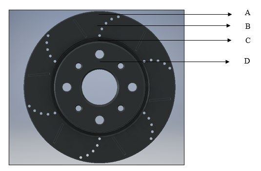
The face of the rotor is sectioned at 4 points A, B, C, D, Figure 3 to determine critical zones.
Section A is found at the outer edge of the brake disc face in line with the centre line.
Section B is found on the middle of the contact friction face of the brake disc.
Section C is found at the bottom of the Brake disc hat connecting to the friction face.
Section D is the top of the hub where the disc brake is bolted.
Figure 3: Marked off sections of the Disc brake model.
4. Results of Static Structural and Steady State Thermal Analysis on ANSYS.
Figure 4 Stress results of the Combination disc with a Figure 5: Deformation results of the Combination
Maximum load of 35KN disc with a Maximum Load of 35KN
© IEOM Society International 7020Proceedings of the 11th Annual International Conference on Industrial Engineering and Operations Management
Singapore, March 7-11, 2021
Table 1: Minimum and Maximum Results of Stress and Deformation
Force Grooved Combination
(KN) Section Structural Stress Disc Brake Disc Brake
Section
20 A Minimum Deformation (m) 0.00011979 0.00012632
Section
35 A Maximum Deformation (m) 0.0002149 0.00021687
Section Minimum Von Mises Equivalent
20 A Stress (MPa) 25.086 10.972
Section Maximum Von Mises Equivalent
35 A Stress (MPa) 35.581 20.797
Section
20 B Minimum Deformation (m) 0.000006655 0.00008642
Section
35 B Maximum Deformation (m) 0.00014321 0.00012048
Section Minimum Von Mises Equivalent
20 B Stress (MPa) 25.086 32.912
Section Maximum Von Mises Equivalent
35 B Stress (MPa) 34.682 41.482
Section
20 C Minimum Deformation (m) 0.00005324 0.000056144
Section
35 C Maximum Deformation (m) 0.000071634 0.00048193
Section Minimum Von Mises Equivalent
20 C Stress (MPa) 31.357 32.913
Section Maximum Von Mises Equivalent
35 C Stress (MPa) 56.043 62.371
Section
20 D Minimum Deformation (m) 0 0
Section
35 D Maximum Deformation (m) 0 0
Section Minimum Von Mises Equivalent
20 D Stress (KPa) 1436 2246.9
Section Maximum Von Mises Equivalent
35 D Stress (KPa) 4.668 3.779
© IEOM Society International 7021Proceedings of the 11th Annual International Conference on Industrial Engineering and Operations Management
Singapore, March 7-11, 2021
Figure 6: Grooved Disc Brake Temperature Figure 7: Combination Disc Brake Temperature
simulation graphical result. simulation graphical result.
Figure 8: Grooved Disc Brake steady thermal Figure 9: Combination Disc Brake seady thermal
profile simulation graphical result. profile simulation graphical result.
Table 2: Temperature and Heat Flux results of different brake disc designs.
Type Value Steady State Thermal Analysis
Temperature Total Heat Flux
o
C W/m2
Grooved Disc Maximum 1216.1 1.5042 x 10⁶
Brake Minimum 410.18 11984
Grooved and Maximum 1067.7 1.3548 x 10⁶
Drilled Disc Minimum 340.18 6850
Brake
5. Discussion
From the results of stress simulations in Figures 4 and 5, Section C experienced the greatest stress concentrations and
Section A the greatest displacements under different loads. The higher the load exerted on the brake the higher the
stress values recorded that lead to the largest displacements. The stress experienced by both disc brake designs falls
within the allowable yield stress of grey cast iron and can be suitably used without permanent failure. Section C can
be strengthened with a new design if needed in future studies and reasons why it’s a critical section for stress. Resultant
© IEOM Society International 7022Proceedings of the 11th Annual International Conference on Industrial Engineering and Operations Management
Singapore, March 7-11, 2021
Von Mises Stress experienced on the brake discs are in line with results from previous studies completed (Da Silva
and Kallon, 2019j).
5.1 Assumptions
• The hub of the rotor is fixed during simulation when the loads are applied.
• The point load is acting at a tangent on the edge of the grooved disc brake and the drilled and grooved disc
brake.
• The load is assumed to be centralised on both the brake systems.
• The load acting at a tangent on the grooved-disc brake edge and the drilled and grooved disc brake disc edge
is assumed to be linear.
• The rotor has rotational motion in an x plane and y plane direction only.
• The rotor experiences a specified angular velocity.
• The rotor experiences no torsional and shear force during loading
5.2 Thermal simulation discussion
The results recorded from the graphical solutions produced by the steady state thermal simulation revealed that the
grooved disc brake would experience a maximum temperature of 1216.1oC and a maximum heat flux of 1.5042 x 10⁶
W/m2 on Section A, Figures 6 and 8. The combination disc brake experienced a maximum temperature of 1067.1 oC
and a total heat flux of 1.3548 x 10⁶ W/m2 Section A, Figures 7 and 9.
When temperatures experienced by a disc brake are lowered the risk of brake fade occurring which is a major cause
of brake failures due to excessive heat decreases. Heat was allowed to dissipate more evenly throughout the disc to
match the surrounding temperature. The above simulations determined minimum and maximum results that would be
experienced by the disc brakes at constant conditions that were placed.
The combination grooved and drilled disc brake experienced a difference in temperature of 149oC less and a heat flux
difference of 0.1494106 W/m2. The heat dissipated in the combination disc brake allowed for better heat dissipation
due to the increased holes that were drilled to allow heat to escape. The added design features created a design of a
brake disc with a stronger thermal diffusivity than a standard grooved disc. The overall heat flux was found to be less
in the combination disc reflecting that the overall heat flowing through the unit at a specific time was less than the
grooved disc. The results show that the combination of drilling and grooving allow for greater heat dissipation on the
disc brake rotors. The results received from the simulations are slightly higher than previous studies completed where
maximum temperatures recorded for a drilled brake disc with a maximum temperature recorded for a grey cast iron
brake was 563.62- 925 oC. The design parameter of each disc is different and would reflect different results depending
on the amounts of holes drilled and the size of each hole. The brake disc thickness also contributes to an increase in
the temperatures recorded in other studies. The overall maximum temperatures determined in this simulation were
created by constant pressure that had no change over a specific time. The combination of drilling and grooving resulted
in a reduced temperature reading allowing for better heat dissipation within the disc decreasing the chances of brake
fade.
5.3 Assumptions
• The specific heat of Grey Cast Iron used 500 J/kgK
• Calculated heat flux for the brake discs was 143.5KW/m3
• Steady State Simulation create results on constant conditions and parameters with no effect of time changes.
• Initial brake temperature is set at 22 oC
6. Conclusion
A static structural analysis was performed using ANSYS on the different brake system models with a point load
exerted tangent to both brake discs on the centre line of the rotors. The point load exerted a linear force on the system
with the following loads 20KN, 23KN, 26KN, 29KN, 32KN and 35KN. This point load simulated the pressure exerted
on the disc brake rotor by the disc pad during heavy braking. The simulation provided the stress concentrations and
displacement results at specific points on the brake discs that were marked off Section A outer edge of the friction
© IEOM Society International 7023Proceedings of the 11th Annual International Conference on Industrial Engineering and Operations Management
Singapore, March 7-11, 2021
surface of the disc face, B middle of the friction surface of the brake disc face, C inner filleted race below the rotor
hat and D the rotor hat that is fixed.
According to the recorded results from the static structural simulation the results and graphs developed Section C –
the inner filleted race below the rotor hat on both disc designs had the greatest values of stress recorded. The grooved
disc brake experienced a maximum stress of 56.043MPa and the combination of drilled and grooved disc brake
experienced a maximum stress of 62.371MPa with the largest exerted load of 35KN.
On the stress vs displacement graphs, the greater the stress on a section the greater the displacement experienced by
the brake disc, it was found that Section A experienced the greatest displacement on both disc brake designs when the
linear force was exerted during the simulation. The maximum deformation on both disc brakes was found at Section
A- outer edge of the friction surface of the disc face. The deformation experienced by the grooved disc brake at an
exerted load of 35KN was 0.0002149m and the drilled and grooved disc brake experienced a deformation of
0.00021687m. Section D experienced 0.00m deformation and almost negligible stress concentrations as this section
was fixed simulating bolting the disc brake to the wheel hub.
According to the results it can be determined that Section C is a critical zone on the designed brake systems in terms
of stress experienced under load and Section A of the brake disc experienced the greatest deformation. A critical zone
is a section that highlights during the simulation and records the highest stress and displacement values when a force
is exerted. The greatest stress was recorded within Section C and the greatest displacement was found at Section A
when a linear force was applied. Drilling holes on a disc brake is known to weaken the overall structure and integrity
of the disc brake and may make it less durable due to removal of material. Less material means less overall strength.
According to our results it can be seen that the Combination disc brake experienced slightly higher stress and
deformations than the grooved disc brake. This can be attributed to a flaw within the created design. The simulation
allows these flaws and critical areas to be determined to better the required design without having to apply destructive
testing on the disc brake rotor.
A Steady State thermal analysis was then completed on both brake designs to determine the highest temperature and
total heat flux that would be experienced. This simulation allowed results to be obtained at a steady state and not
subject to transient or time lapse. The results recorded would reflect the maximum readings the disc would experience.
The increased drilling on the combination of drilled and grooved disc brake would have experienced less temperature
increases as the added ventilation would allow the disc brake to cool faster when under heavy and continuous braking.
According to our results it was shown that increased ventilation such as a combination of both drilling and grooving
would allow for better heat dissipation. The grooved disc brake experienced a maximum temperature of 1216.1oC and
a maximum heat flux of 1.5042 x 10⁶ W/m2. The combination disc brake experienced a maximum temperature of
1067.1oC and a total heat flux of 1.3548 x 10⁶ W/m2. A difference of 194 oC but both maximum temperatures
experienced in Section A of the disc brake.
Safety in vehicles remains a main focus in all modern-day vehicles as mass and speeds increase. Brakes discs and the
ability to slow a vehicle down is a critical safety aspect of all vehicles. Brake disc designs and efficiency are widely
used to continuously develop technology for the most effective and economical designs. The results presented the
difference in durability of two different brake disc designs created in grey cast iron. The grooved disc brake design
experienced less stress and deformations when a load was exerted than the combination of drilled and grooved.
However, the combination disc brake experienced less temperatures increases and a lower heat flux. The built-up heat
and gas were more readily able to escape preventing the disc from reaching the same temperatures that the grooved
disc brake experienced. Lower temperatures allow for better efficiency of brake discs at more constant heavy braking
maintaining good performance. This prevent brake fade and thermal cracking from occurring during heavy constant
braking. The combination of drilled and grooved may have experienced slightly higher stress values but experienced
lower temperature readings under a load and is considered the better design. The Combination drilled- and grooved
disc rotor contains both the aesthetics and functionality of the grooved disc brake with better performance.
References
Da Silva, S. & D.V.V, K., 2019. FEA of Different Brake Discs. Procedia Manufacturing, Volume 35, pp. 181-186.
Deekshith, C., Udaya, K. & Vijaya Kumar, Y., 2017. Design, Analysis and Manufacturing of Disc Brake Rotor.
International Journal Of Engineering Research And Development, 13(11), pp. 15-23.
© IEOM Society International 7024Proceedings of the 11th Annual International Conference on Industrial Engineering and Operations Management
Singapore, March 7-11, 2021
Grzes, P. et al., 2016. The numerical–experimental scheme for the analysis of temperature field in a pad-disc
braking system of a railway vehicle at single braking. International Communications in Heat and Mass Transfer, 10
April, Volume 75, pp. 1-6.
Limpret, R., 2011. Brake Design and Safety. 3rd ed. Warrendale: SAE International.
Malott, B. & Lou, G., 2009. Grooved Disc Brake Rotor. United States of America, Patent No. US 2009/0050422
A1.
Manjunath, T. & Suresh, P., 2013. Structural and Thermal Analysis of Rotor Disc of a Disc Brake. International
Journal of Innovative Research in Science, Engineering and Technology, 2(12), pp. 7741-7749.
Masoud, I., Al-Jarrah, J. & Mansour, T., 2014. Manufacturing of Gray Cast Iron Automotive Disc Brake. Indian
Journal of Applied Research, 4(3), pp. 129-131.
Patel, M., Raval, M. & Patel, J., 2016. Design of Disc Brake Rotors. International Journal of Engineering
Development and Research, 4(4), pp. 919-926.
Qian, W., Burgoon, D. L. & . Killeen, S. E., 2001. Brake Rotor Having Aa Array Of Grooves Formed Theron.
United States of America, Patent No. US 6,446,770 B2.
Reyes, A. M., Cruz, C. J., Dr. Diaz, L. & Olegario, E., 2019. Microstructure evaluation of the damage and wear
characteristics of a failed disc brake of a provincial bus.. Materials Today, Issue 16, pp. 1789-1795.
Sanaka, D. S. P. & Kumar, S. k., 2015. Design and Analysis of Drilled Rotor of a Disc Brake. International Journal
of Eminent Engineering Technologies, 2 July, Volume 3, pp. 1-16.
Sporzynski, R. S., Evans, A. C. & Robinette, R. T., 1990. Disc brake rotor. United States of America, Patent No.
4,930,606.
Biographies
Mr Stephen Da Silva is a South African holder of a B-Tech in Mechanical Engineering at the University of
Johannesburg. Mr Da Silva has been working as a District Manager at ESCO Division of the WEIR Group since April
2020. Currently completing his Masters studies, He published one (1) paper in an international conference. Mr Da
Silva is a member of South African Institute of Mechanical Engineering (SAIMechE) and Candidate Technologist
with the Engineering Council of South Africa (ECSA). Mr Da Silva’s primary research areas are System Analysis and
Dynamics, Optimization, Strength of Material, Finite Element Analysis and Processing
Dr Daramy Vandi Von Kallon is a Sierra Leonean holder of a PhD degree obtained from the University of Cape
Town (UCT) in 2013. He holds a year-long experience as a Postdoctoral researcher at UCT. At the start of 2014 Dr
Kallon was formally employed by the Centre for Minerals Research (CMR) at UCT as a Scientific Officer. In May
2014 Dr Kallon transferred to the University of Johannesburg (UJ) as a full-time Lecturer and later a Senior Lecturer
in the Department of Mechanical and Industrial Engineering Technology (DMIET). Dr Kallon has more than twelve
(12) years of experience in research and seven (7) years of teaching at University level, with industry-based
collaborations. He is widely published, has supervised from Masters to Postdoctoral and has graduated seven (7)
Masters and four (4) Honors Candidates. Dr. Kallon’s primary research areas are Numerical Modelling in the fields
of: Acoustics Technologies, Mathematical Analysis and Optimization, Vibration Analysis, Water Research and
Engineering Education. To date, Dr Kallon has served as a reviewer to the following reputable internationally
recognized journals: ASEJ, IJMAIEJ, JMMM, JPAS (SL), Minerals (MDPI), R&DJSAIMechE, Science Progress
(SP) and SoTE. He has also served as Masters External Examiner to the TUT (SA) for two Masters dissertations.
© IEOM Society International 7025Proceedings of the 11th Annual International Conference on Industrial Engineering and Operations Management
Singapore, March 7-11, 2021
© IEOM Society International 7026You can also read