DJ Series Butterfly Valves
←
→
Page content transcription
If your browser does not render page correctly, please read the page content below
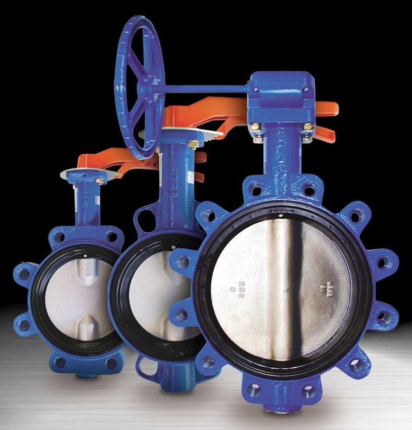
DJ Series
Butterfly Valves

                   European Edition
KITZ DJ Series Butterfly Valves
Flange Table
Wafer Lugged
:Standard mounting
:Special mounting (Proper centering is required)
:Not coverd by standard DJ series
Explanation of Product Code
G – PN16 DJ L M E
1 2 3 4 5 6
1 Valve operation 2 Class 3 Valve material and design
None: Lever handle PN16: BS4504 PN 16 DJ: Ductile iron DJ series
G: Gear 150: ASME 150 psi
200: ASME 200 psi
10: JIS 10K
16: JIS 16K
4 Connection 5 Disc material 6 Seat material
None: Wafer None: Ductile iron (Ni-plated) None: NBR (Buna-N)
L: Lugged U: 304 stainless steel E: EPDM
M: 316 stainless steel Alternative: Available on request, Refer to
A: Aluminum Bronze KITZ Corporation for further
information.
This catalog uses MPa, a SI unit, for indication of pressures.
For readers’ convenience, however, kgf/cm2 is also used as an additional information.KITZ DJ Series Butterfly Valves
KITZ DJ Series Butterfly Valves
Thorough pursuit of functions required for butterfly valves
Variety of product ranges to comply with customers’ requirements
Design Features
Moulded-in (bonded) seat structure Replaceable seat structure
Polyacetal stem NBR (Buna-N) or
bearing EPDM O-ring
NBR (Buna-N) or
Stainless steel
EPDM O-ring
stem
Stainless steel stem
PTFE stem bearing
Ductile iron body NBR (Buna-N) or
with protective EPDM seat booted
paint coating to valve body
NBR (Buna-N) or Ductile iron body
EPDM seat firmly with protective
molded-in (bonded) paint coating
to valve body
Ductile iron with Ductile iron with ENP
ENP or stainless or stainless steel disc
steel disc
Zinc die-cast plug
with chromate PTFE stem bearing
coating
WRAS Approval Integral ISO 5211 actuator mounting flange
All KITZ EPDM seat materials are fully in accordance with latest Any pneumatic or electric valve actuators provided with ISO 5211
WRAS standards. valve mounting flanges can be easily mounted for actuation of valves
in the field.
Non-peeling seat-to-body construction
Moulded-in (bonded) seat structure is employed for 2” to 12”. Larger Low valve operating torque
sized valves are provided with replaceable seat. This non-peeling Low operating torques are designed low for extension of valve
seat-to-body construction assures maintenance-free application for service life and economic consideration in selection of valve
1 2
high fluid velocity service,* vacuum* service and handling surging operating devices.
fluid velocity. It also guarantees peel-free valve mounting on
pipelines. Light-designed for operation efficiency
*1 4 meter / second maximum for on-off liquid handling. Designed much lighter than our conventional series for operation
*2 Up to 30 torr. efficiency in piping
Spherical design for discs and seats Emission-free stem sealing mechanism
Rubber seats are spherically designed where they contact top and Prevention of external fluid leakage is maximized with a rubber O-
bottom stems. This protects widely designed rubber seats from ring assembled around the top stem and tight contact between
peeling or deformation for prolonged service life of valves. Thinly spherically designed rubber seat and spherically designed top and
streamlined metal discs are the results of elaborate laboratory study bottom end of the disc.
to ultimately minimize the pressure loss.
Index plate
Choice of materials and
3
operating devices Index plate has 10 locking positions as standard.
Choice among 4 disc and 2* seat materials and manual, pneumatic or
electric valve operating devices makes service applications highly Condensation-proof
versatile. Condensation-proof type is optionally available with heat insulating plate
*3 Additional seat materials available subject to requirements. (size 2” to 8”) or stainless steel stand (size 10” to 24”).
1KITZ DJ Series Butterfly Valves
Technical Specifications
Maximum service pressure
BS PN16 1.6MPa 16kgf/cm2
ASME 150 psi 1.38MPa 14kgf/cm2
ASME 200 psi 1.03MPa 11kgf/cm2
JIS 10K 0.98MPa 10kgf/cm2
JIS 16K 1.57MPa 16kgf/cm2
KITZ lugged type butterfly valves are rated for dead end service to full working pressure of the valve with the downstream flange removed.
In dead end service exceeding 96 hours, a downstream flange is recommended.
Body material
Ductile iron EN-GJS-450-10, Equivalent to ASTM A536 Gr. 65-45-12, BS 2789 Gr. 40/10
Obsolete Standard.
Service temperature range
NBR (Buna-N) seat 0 to
EPDM seat 0 to
Continuous service temperature range 0 to
There are some fluid type restrictions for the service at 130
Applicable standards
Valve design API 609, MSS-SP67, MSS-SP25
Face to face dimensions BS 5155 (Short pattern), ISO 5752-20, JIS B 2002 46 Series
Coupling flanges
Wafer type BS EN 1092 PN10/PN16
ASME Class 150
BS 10 Table D/Table E
JIS 10K/16K
Lugged type BS EN 1092 PN16
ASME Class 150
JIS 10K
Test pressure
BS PN16 Shell test 2.4 MPa 24.5kgf/cm2 Hydrostatic
Seat test 1.76MPa 17.9kgf/cm2 Hydrostatic
0.6 MPa kgf/cm2 Pneumatic
ASME 150 psi Shell test 1.55MPa 15.8kgf/cm2 Hydrostatic
Seat test 1.14MPa 11.6kgf/cm2 Hydrostatic
0.59MPa kgf/cm2 Pneumatic
ASME 200 psi Shell test 2.07MPa 21.1kgf/cm2 Hydrostatic
Seat test 1.52MPa 15.5kgf/cm2 Hydrostatic
0.59MPa kgf/cm2 Pneumatic
JIS 10K Shell test 1.47MPa 15kgf/cm2 Hydrostatic
Seat test 1.08MPa 11kgf/cm2 Hydrostatic
0.59MPa 6kgf/cm2 Pneumatic
JIS 16K Shell test 2.36MPa 24kgf/cm2 Hydrostatic
2
Seat test 1.73MPa 17.6kgf/cm Hydrostatic
0.59MPa 6kgf/cm2 Pneumatic
2KITZ DJ Series Butterfly Valves
Flow coefficient (Cv) Materials
1 420 stainless steel for 16” and larger
2 Metal backed PTFE for 6” and larger
3 Chromate coating
4 420 stainless steel for 16” and larger
5 Ductile iron for size 8”
6 Cast iron for 14” and larger
Cv is defined as the flow in GPM that a valve will carry with a pressure drop of 1.0 psi,
when the media is 60 F (15.6 ) water.
(for handling static clean water with
Liquid flow: Gas flow:
Pressure loss valve fully open)
Q = Cv P/S Q = 1360 Cv P x P1/ST
Q = Liquid flow rate (gallons per minute) Q = Gas flow rate (SCFH std. cu.ft./hr.)
P = Pressure drop across valve (psi) S = Specific gravity of gas (air=1.0) (kPa) (kgf/cm2)
S = Specific gravity of media T = Temp. degrees rankin ( F+460)
P = Pressure drop across valve (psi) 14 18
2 21 2 3 4 5 6 8 10 12 16 20 24
P1 = Upstream pressure (psia) absolute
Note that P must be less than .5
(Flow is critical when P is greater than .5 P1)
Pressure drop 1.0 0.1
P-T rating
MPa(kgf/cm2) 0.1 0.01
PN16
1.6 (16)
1.10 (11.2)
Pressure
0.98 (10) 0.01 0.001
0 10 100 1000 10000
NBR Flow volume (m3/h)
0.49 (5)
Flow characteristics
EPDM
-20 0 70 90 130 100
90
Notes1:There are some fluid type restrictions for the service at 130 .
Contact KIZT for the details. 80
Notes2:P-T rating for sub-zero application is optionally available. Contact
KITZ for technical advice when service conditions may exceed the P- 70
T rating range limited here.
Flow rate (%)
60
Trim material coding 50
40
30
20
10
0 10 20 30 40 50 60 70 80 90 100
Close Open
Valve opening (%)
Alternative seats are available on request.
3KITZ DJ Series Butterfly Valves
Lever Operated
Wafer Type
BS PN16 Design
PN16DJ
ASME 150/200 psi Design
150/200DJ
JIS 10K Design
10DJ
JIS 16K Design
16DJ
of product coding
are trim material coding
H
H1
H2
BS PN16 Design
Dimensions
4KITZ DJ Series Butterfly Valves
Gear Operated
Wafer Type
BS PN16 Design
G-PN16DJ
ASME 150/200 psi Design
G-150/200DJ
JIS 10K Design
G-10DJ
JIS 16K Design
G-16DJ
of product coding
are trim material coding
H
H
H
H2
BS PN16 Design
Dimensions
5KITZ DJ Series Butterfly Valves
Lever Operated
Lugged Type
BS PN16 Design
PN16DJL
ASME 150/200 psi Design
150/200DJL
of product coding
are trim material coding
H
H1
C
H2
BS PN16 Design
Dimensions
6KITZ DJ Series Butterfly Valves
Gear Operated
Lugged Type
BS PN16 Design
G-PN16DJL
ASME 150/200 psi Design
G-150/200DJL
of product coding
are trim material coding
E
F
H3
H
H1
C
H2
BS PN16 Design
Dimensions
7KITZ DJ Series Butterfly Valves
Bolting Data
Wafer type (Either type of below bolting is required)
Hexagon head bolt Hexagon nut
Stud bolt Hexagon nut
Lugged type Size 24” requires additional hexagon head bolts.
Hexagon head bolt Hexagon nut
8KITZ DJ Series Butterfly Valves
Precautions for Trouble-free Operation of
KITZ Butterfly Valves
Valve Selection 5. For valve mounting, set jack bolts under the pipes for
1. Ensure to select a valve with design specifications flat support at the same height, and adjust the flange-
which meet the fluid type and the pressure and to-flange distance so that some 6 mm to 10 mm room
temperature conditions required. may be allowed beside the both sides of the valve
2. Lubricants are applied to discs, rubber seats and body.
PTFE seats as standard to protect their surfaces. Remember that valves here must be left open only by
Oil-free treated types are available as option. Contact 10° from the fully closed position.
KITZ Corporation or its local distributors for the details. 6. Set two bolts into the lower mounting guides of a valve
3. Contact KITZ Corporation or its local distributors for and mount it carefully so that flange faces may not
service with pulverulent bodies. damage resilient seats. (Fig. 2)
7. Then set another two bolts into the upper mounting
Storage and Handling guides of a valve, ensuring the correct centering
Valves must be stored in dry, clean and corrosion-free between pipes and the valve.
environment with no direct exposure to the sun, leaving 8. Trially open the valve to check to see if there is no
valves open by 10° for prevention of permanent distortion disturbing contact between the valve disc and the
of resilient seats. Refrain from overloading valves and flanges.
their actuators, such as storing them in piles or placing 9. Remove the jack bolts, Recommended torque values
other objects on them. set all bolts around the
valve body and tighten
Mounting on Pipelines them alternately and
1. Valves must be mounted on flanges only after flanges diagonally till the flanges
have been welded to pipes and cooled down to the contact the valve body
atmospherical temperature. Otherwise, welding heat (Fig. 3 and 4). Refer to
may affect the quality of resilient seats. the table shown right for
2. Edges of welded flanges must be machined for smooth recommended torque
surface finish so that they may not damage resilient values.
seats during valve mounting. Flange faces must be
free from damage or deformation, and be cleaned to Fig. 2 Fig. 3
remove rust or any other foreign objects so that there
will be no concern of external leakage through valve
and flange connections. Gaskets are not required for
mounting KITZ DJ series butterfly valves.
3. Clean flanges and pipe bores to thoroughly remove
welding spatters, scales and other foreign objects
which may have been left inside.
4. Accurate centering of each couple of upstream and
downstream pipes is essential for trouble-free
operation of valves mounted between them. Incorrect
centering shown in Fig. 1 must be by all means
avoided.
Fig. 1
(a) Fig. 4
(b)
9KITZ DJ Series Butterfly Valves
10.For mounting actuated valves, provide valve supports Valve Operation
to prevent bending of valve necks and reduce valve 1.Valves equipped with manual operators such as
and pipe vibration. levers, and handles of gears must be ONLY
11.Don’t step on valve necks or valve handwheels. MANUALLY operated. Application of an excessive
12.Don’t mount valves of DN350 and larger with their external force to operate valves may result in
operations upside down. malfunction of valves and their operators.
13.Don’t mount butterfly valves directly to check valves or 2.Ensure to fully open valves before a loop test of the
pumps, which may cause damage to them by the disc piping system is carried out with line pressure higher
contacts. than the nominal pressure of tested valves. Never use
14.Don’t mount valves to downstream sides of elbows, closed valves in place of blind flanges.
reducers or regulating valves where fluid velocity 3.When valves need to be dismantled from pipes for
changes. It is recommended to install valves approx- maintenance or any other cause, ensure to thoroughly
imately 10 times of the valve nominal sizes away from releave the line pressure beforehand. Loosening
them for such cases. piping bolts under line pressure causes a danger. Any
15.Mount valves taking consideration of the effects which residual fluid left inside the pipeline must be
discs are given by fluid velocity or pressure chages in completely drained.
the pipings. Refer to the illustrations. (Fig.5) 4.Users should contact KITZ Corporation or its local
Contact KITZ Corporation or its local distributors for distributors for technical advice, when valves should
the details. be continuously pressurized while left open by 30° or
less.
Fig.5 5.Don't use position indicators to operate valves, or
overload position indicators. This may cause damage
Mounting to bent pipe Mounting to pump outlet
to indicators.
Pump
shaft Centrifugal pump
6.Ensure to use blind flanges when butterfly valves are
(Vertical shaft) mounted at the end of pipelines.
10D
7.Standard actuators are referenced in this catalog for
actuated valve operation. Contact KITZ Corporation or
its local distributors for mounting optional actuators.
8.Contact KITZ Corporation for service at hopper or
pump outlets.
9.Avoid touching gear operators and actuator stopper
bolts accidentally.
10.It is recommended to perform periodical inspection for
Centrifugal pump
(Horizontal shaft) • Making sure of valve opening degree
• Checking loosened bolts and leakage at each
connection
• Checking vibration and noise
Pump
shaft 11.Refer to instruction manual for other precautions. Also
refer to actuator catalogs and instruction manuals for
10D
actuated valves.
Pump
shaft
10D
Axial flow pump
10D:10 Times Length of bore size.
10CAUTION
1-10-1, Nakase, Mihama-ku, Chiba 261-8577, Japan
International Sales Dept. Phone : 81-43-299-1730, 1732 and 1733
Fax : 81-43-299-0121
KITZ Corporation UK Office
Windsor House, Cornwall Road, Harrogate, North Yorkshire HGI 2PW, U.K.
Phone : 44 (0) 1423-875225
Fax : 44 (0) 1423-875226
www.kitzcorporation.com
Distributed byYou can also read