Dodge Durango Pursuit Upfit Guide 2021 - FCA Fleet
←
→
Page content transcription
If your browser does not render page correctly, please read the page content below
2021
Dodge Durango Pursuit
     Upfit Guide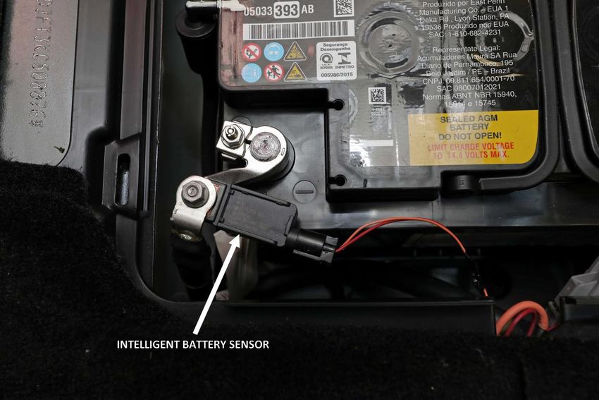
SAFETY NOTICE
This publication’s purpose is to provide technical training information to individuals in the
automotive trade. All test and repair procedures must be performed in accordance with
manufacturer’s service and diagnostic manuals. All warnings, cautions, and notes must be
observed for safety reasons. The following is a list of general guidelines:
Proper service and repair is critical to the safe, reliable operation of all motor vehicles.
The information in this publication has been developed for service personnel, and can help
when diagnosing and performing vehicle repairs.
Some service procedures require the use of special tools. These special tools must be used
as recommended throughout this Technical Training Publication, the diagnostic manual, and
the service manual.
Special attention should be exercised when working with spring- or tension-loaded
fasteners and devices such as E-Clips, circlips, snap rings, etc. Careless removal may cause
personal injury.
Always wear safety goggles when working on vehicles or vehicle components.
Improper service methods may damage the vehicle or render it unsafe.
Observe all warnings to avoid the risk of personal injury.
Observe all cautions to avoid damage to equipment and vehicles.
Notes are intended to add clarity and should help make your job easier.
Cautions and warnings cover only the situations and procedures Stellantis has encountered and
recommended. Neither Stellantis nor its subsidiaries or affiliates can know, evaluate, and advise
the service trade of all conceivable ways in which service may be performed, or of the possible
hazards for each. Consequently, Stellantis and its subsidiaries and affiliates have not
undertaken any such broad service review. Accordingly, anyone who used a service procedure
or tool that is not recommended in this publication must be certain that neither personal
safety, nor vehicle safety, is jeopardized by the service methods they select.
No part of this publication may be reproduced, stored in a retrieval
system or transmitted, in any form or by any means, electronic,
mechanical, photocopying, recording, or otherwise, without the prior
written permission of Stellantis.
Stellantis reserves the right to make changes from time to time,
without notice or obligation, in prices, specifications, colors and
materials, and to change or discontinue models. See your dealer for
the latest information.
Copyright © 2021 Stellantis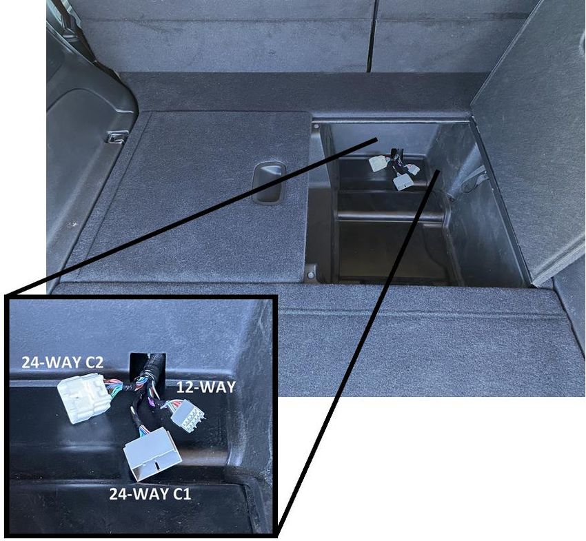
TABLE OF CONTENTS
ABOUT THIS GUIDE ......................................................................................................................... 1
FLEET WEBSITE ................................................................................................................................ 2
VEHICLE DIMENSIONS ..................................................................................................................... 3
ELECTRICAL...................................................................................................................................... 4
   CAN Communication and Cybersecurity ..................................................................................... 4
   Radar or other aftermarket CAN bus connections ..................................................................... 4
   Basic Electrical Tips ..................................................................................................................... 5
   Fuses / Power Distribution Centers ............................................................................................ 7
   Power and Ground .................................................................................................................... 12
   Pass Through Circuits ................................................................................................................ 19
VEHICLE SYSTEMS INTERFACE MODULE (VSIM) ........................................................................... 21
   VSIM Upfitter connector location ............................................................................................. 21
   Underhood pass-through circuits ............................................................................................. 22
   Upfitter CAN bus ....................................................................................................................... 23
   12-way Upfitter connector ........................................................................................................ 26
   24-way Upfitter C1 connector (gray) ........................................................................................ 27
   24-way Upfitter C2 connector (white) ...................................................................................... 29
FLEET SETTINGS MENU ................................................................................................................. 31
LIGHTING ....................................................................................................................................... 33
   Police Dome Lamps ................................................................................................................... 33
   Spot Lamp(s).............................................................................................................................. 34
EQUIPMENT MOUNTING PLATE ................................................................................................... 36
USB MEDIA HUB REMOVAL .......................................................................................................... 37
RESTRAINTS ................................................................................................................................... 38
   Occupant Restraint System Overview ....................................................................................... 38
   Driver Airbag (DAB) Deployment Zone ..................................................................................... 39
   Side Curtain Airbag Deployment Zone ...................................................................................... 46
   Side Airbag Deployment Zone ................................................................................................... 48
   Occupant Restraint System Wiring ........................................................................................... 49
   Occupant Restraint System Verification ................................................................................... 49
VEHICLE STORAGE ......................................................................................................................... 50
   General Storage Recommendations ......................................................................................... 50
   Battery Maintenance ................................................................................................................ 51
   Shipping Mode .......................................................................................................................... 52
ABOUT THIS GUIDE
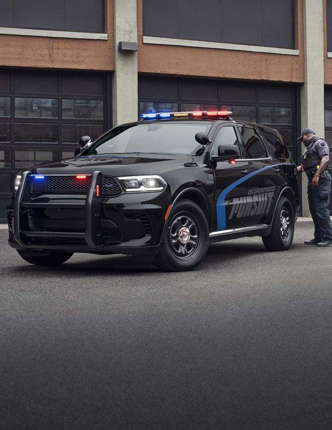
Figure 1: Dodge Durango Pursuit Interior with aftermarket equipment
This guide has been assembled to give facilities technical information on the Dodge Durango
Pursuit vehicle that may be required when installing accessories or equipment for use in fleet
applications. Not all vehicles purchased are equipped with the same accessories, so there may
be items covered in this guide that are not featured on the vehicle purchased by your agency.
Dodge Durango Pursuit Upfitter Guide 1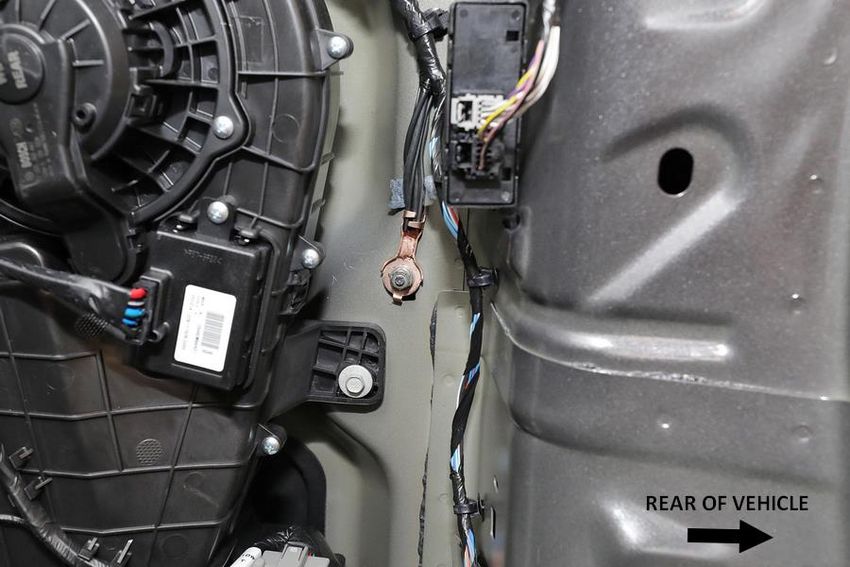
FLEET WEBSITE

                    Figure 2: Fleet Website, aftermarket equipment shown

The Fleet website is another resource for up-to-date specification information on the Dodge
Durango Pursuit and other fleet vehicles. An electronic copy of additional upfitter information,
as well as options and service recommendations, are also found at www.fcausfleet.com.

Dodge Durango Pursuit Upfitter Guide                                                               2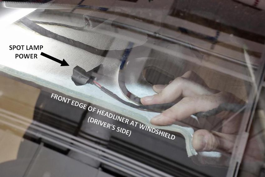
VEHICLE DIMENSIONS

                               Figure 3: Vehicle Dimensions

   A.   Length             5082 mm (200.1 in.)
   B.   Front overhang     869 mm (34.2 in.)
   C.   Wheelbase          3042 mm (119.8 in.)
   D.   Rear overhang      1171 mm (46.1 in.)
   E.   Height             1850 mm (72.8 in.)
   F.   Width              1910 mm (75.2 in.)

Dodge Durango Pursuit Upfitter Guide                          3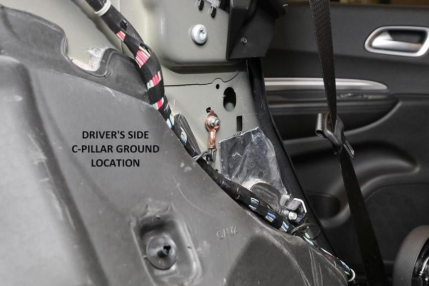
ELECTRICAL
CAN Communication and Cybersecurity

The vehicle security gateway blocks unauthorized CAN communication from the vehicle
diagnostic connector. Legislated/regulated diagnostic modes $01-$0A under SAE J1979 are still
fully supported for aftermarket tools.

Radar or other aftermarket CAN bus connections

Radar speed measuring equipment or other police equipment may require a connection to the
vehicle to determine the police vehicle’s speed. The Durango pursuit provides two connection
methods for this purpose:
   1. A hardwired output from the Vehicle Systems Interface Module (VSIM) which gives
        vehicle speed as a square wave output. Refer to the section on the VSIM 24-way upfitter
        C2 connector cavity 19 for more details on this signal.
   2. A CAN output from the VSIM upfitter bus which gives vehicle speed as a J1939 CAN
        signal. Refer to the section Upfitter CAN bus within the VSIM information for more
        details on this connection.

CAUTION: Do not connect a radar unit or any other police equipment to the vehicle’s
         diagnostic connector or the vehicle operating CAN bus. These connections are
         designed only for authorized service tools during vehicle maintenance. Other
         equipment connected to the vehicle in this manner can induce unexpected faults
         and/or degraded vehicle performance and will not be covered by the vehicle’s
         manufacturer warranty.

NOTE:      There are sensors for the keyless entry and antilock brake systems, and an
           occupant restraint controller located under the center console, or equipment
           mounting plate if equipped. Make sure during upfit that the sensors are not
           repositioned. Sensor placement is critical for proper system operation.

NOTE:      The equipment mounting plate must be removed while holes are drilled in it. The
           graphics on the plate indicate where there is the least amount of clearance under
           the plate. Be extra careful in this area that any fasteners used for mounting
           equipment will not contact the vehicle electronics when the mounting plate is
           reinstalled into the vehicle.

NOTE:      Do not remove the occupant restraint controller without first disconnecting the
           battery and waiting two minutes. Follow information in the Mopar Service Library
           for disabling the restraint system. Failure to do so could cause airbag deployment.

Dodge Durango Pursuit Upfitter Guide                                                             4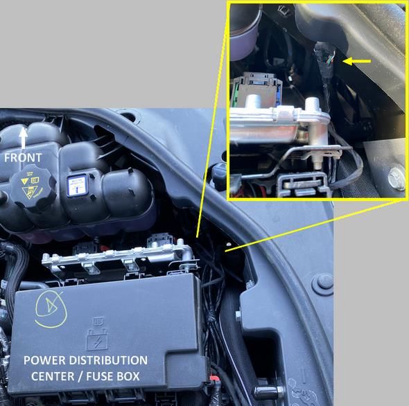
Basic Electrical Tips
ISO Relays
Figure 4: ISO Relays
ISO relays conform to the specifications of the International Organization for Standardization
for common size and terminal pattern. ISO relays are used in many applications such as the
starter, horn, electric fan, air conditioning clutch, auto shut down, and fuel pump circuits.
Relay connection terminals are defined as follows:
Terminal 30 is usually connected to battery voltage. This battery voltage source can be
switched on or off by the ignition switch, or un-switched, connected directly to the battery.
Terminal 87A is connected to Terminal 30 in the de-energized position.
Terminal 87 is connected to Terminal 30 in the energized position. When energized, the
relay supplies battery voltage to Terminal 87, or removes battery voltage from a device
connected to Terminal 87A.
Terminal 86 is connected to the electromagnet and is usually connected to a switched
battery voltage source.
Terminal 85 is connected to the electromagnet and is usually connected to a switched or
unswitched ground
Dodge Durango Pursuit Upfitter Guide 5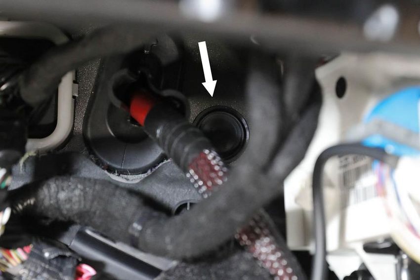
Micro Relays

                                     Figure 5: Micro Relays

Micro relays and micro 280 relays perform the same function as ISO relays but are smaller in
size and have different terminal patterns. A map of the pattern and terminal identification is
usually located on the top or side of the relay.

Dodge Durango Pursuit Upfitter Guide                                                             6
Fuses / Power Distribution Centers

There are two fuse and relay locations on the vehicle for the standard electrical systems. The
fuse values and positions for the standard electrical systems are described below.

CAUTION:        When installing the Power Distribution Center (PDC) cover, make sure it is
                properly positioned and latched to prevent water from getting into the PDC and
                causing an electrical system failure. When replacing a blown fuse, use only a fuse
                having the correct amperage rating. The use of a fuse with a rating other than
                indicated may result in an electrical system overload. If a properly rated fuse
                continues to blow, it indicates a problem in the circuit that must be corrected.

                                     Figure 6: Underhood PDC

                                    Table 1: Underhood Fuses
Note: Fuse specifications may vary slightly from the table below and based on vehicle content,
      refer to the vehicle service information for the most current information.
    FUSE         CIRCUIT
                                                     FUNCTION                             RATING
   NUMBER         NAME
   Ckt Brkr 1      F981      RR POWER WINDOWS / POWER WINDOW (DRIVER) / (PASSENGER)         25A
   Ckt Brkr 2      A942                    POWER SEAT - DRIVER / MEMORY                     25A
   Ckt Brkr 3      A949                      POWER SEAT - PASSENGER                         25A
       F1                                           NOT USED
       F2                                           NOT USED
       F3                                           NOT USED
       F4          A107                         ESP PUMP MOTOR                              60A
      F5           F105                    POLICE 20A IGNITION/RUN FEED #1                  20A

Dodge Durango Pursuit Upfitter Guide                                                              7
FUSE CIRCUIT
FUNCTION RATING
NUMBER NAME
F6 NOT USED
F7 START / STOP 30A
F9 T108 VACUUM PUMP (V6 ONLY) 30A
F10 A903 CBC - FEED 2 (EXT. LIGHTS) 40A
F11 A400 PWR - TRAILER TOW ELECTRIC BRAKE BATTERY FEED 30A
F12 A906 CBC - FEED 3 (POWER LOCKS) 40A
F13 C7 HVAC BLOWER MOTOR - FT 40A
F14 A904 CBC - FEED 4 (EXT. LIGHTS) 40A
F15 NOT USED
F16 NOT USED
F17 F103 POLICE 20A IGNITION/RUN FEED #3 20A
F18 A101 POLICE 20A BATTERY FEED #1 20A
F19 F102 POLICE 20A IGNITION/RUN FEED #2 20A
F20 A925 PASSENGER DOOR CONTROL MODULE 30A
F21 NOT USED 20A
F22 A209 ENGINE CONTROL MODULE 20A
F23 A905 CBC - FEED 1 (INT. LIGHTS) 30A
F24 A924 DRIVER DOOR CONTROL MODULE 30A
F25 FT WIPER 30A
F26 A200 ESP - ECU & VALVES 30A
F27 NOT USED 20A
F28 L111 TRAILER TOW - BACKUP LIGHTS 20A
F29 L76 TRAILER TOW - PARKING LIGHTS 20A
TRAILER TOW (RECEPTACLE) / TRAILER TOW
F30 A100 30A
(SEPARATE E-BRAKE)
F31 A102 POLICE 20A BATTERY FEED #2 20A
F32 A194 DTCM 30A
F33 A103 POLICE 20A BATTERY FEED #3 20A
F34 NOT USED
F35 A991 VSIM FEED 30A
F36 C15 REAR DEFROSTER (EBL) 30A
F37 C51 HVAC RR MODULE - BLOWER 25A
F38 A401 POWER INVERTER - 115V AC 30A
F39 A111 POWER LIFTGATE MODULE 30A
F40 F927 HEADLAMP LEVELING 10A
F41 NOT USED
F42 X21 HORN DRIVER 20A
F43 NOT USED
F44 A900 DIAGNOSTIC PORT 10A
F45 A902 CYBERSECURITY MODULE 5A
F46 NOT USED
F47 NOT USED
F48 NOT USED
Dodge Durango Pursuit Upfitter Guide 8FUSE CIRCUIT
FUNCTION RATING
NUMBER NAME
F49 A391 ICS / HVAC 10A
F50 A206 ELSD
F51 A910 KIN / RF HUB 15A
F52 NOT USED
F53 L615 TRAILER TOW - LT TURN/STOP LIGHTS 20A
F54 NOT USED
F55 NOT USED
F56 NOT USED
F57 NOT USED
F58 NOT USED
F59 A382 POLICE SPOT LAMP - LEFT 15A
F60 A190 TRANSMISSION CONTROL MODULE 15A
F61 NOT USED
F62 C3 A/C CLUTCH 10A
F63 F343 IGNITION COILS / IGNITION COIL CAPACITORS 20A
F64 F342 FUEL INJECTORS / ECM 25A
F65 NOT USED
F56 F982 INSIDE REARVIEW MIRROR / USB PORT 10A
F67 A383 USB CHARGING PORT - REAR 15A
F68 W13 REAR WIPER MOTOR 20A
F69 A301 POLICE SPOT LAMP - RIGHT 15A
F70 N1 FUEL PUMP MOTOR 20A
F71 A931 AMPLIFIER / ANC 30A
F72 T753 ECM (V6 ONLY) 10A
F73 NOT USED
F74 NOT USED
F75 DUAL BATT CTRL 10A
F76 F941 ESP 10A
F77 F946 DRIVE TRAIN CONTROL MODULE 10A
F78 F942 ECM / ELECTRIC POWER STEERING 10A
F79 NOT USED
F80 A990 UGDO 10A
F81 L614 TRAILER TOW - RT TURN/STOP LIGHTS 20A
F82 A381 STEERING COLUMN CONTROL MODULE / CRUISE CONTROL 10A
F83 A140 FUEL DOOR 10A
F84 A394 INSTRUMENT CLUSTER 15A
F85 F929 AIRBAGS 10A
F86 F945 AIRBAGS 10A
F87 NOT USED
F88 F949 INSTRUMENT PANEL CLUSTER 15A
F89 NOT USED
Dodge Durango Pursuit Upfitter Guide 9FUSE CIRCUIT
FUNCTION RATING
NUMBER NAME
F90 F983 POWER OUTLET - CARGO AREA BATTERY FED POSITION
F91 F983 POWER OUTLET - CARGO AREA IGN FED POSITION (DEFAULT) 20A
F92 F985 REAR CONSOLE LAMP / POWER OUTLET - REAR OF CONSOLE 10A
F93 F986 POWER OUTLET - LEFT OF GLOVEBOX 20A
F94 A195 SHIFTER / TRANSFER CASE SWITCH 10A
F95 F923 REAR CAMERA / BLIND SPOT SENSOR 10A
F96 F928 RELAY COILS - POLICE IGNITION/RUN #1, #2, #3 10A
F97 NOT USED
F98 NOT USED
F99 F948 HVAC / DASM / HLFM / PARKTRONICS 10A
F100 NOT USED
F101 F910 IN-CAR TEMPERATURE SENSOR / HUMIDITY SENSOR 15A
F102 SPARE 15A
F103 F911 REAR HVAC 10A
F104 A932 POWER OUTLET - IN CENTER CONSOLE 20A
There are also high current fuses in a power distribution center connected to the positive jump
start post.
Figure 7: High Current Fuses
Dodge Durango Pursuit Upfitter Guide 10Table 2: Underhood Relays
Note: Relay specifications may vary slightly from the table below and based on vehicle
content, refer to the service information for the most current information.
RELAY
FUNCTION POPULATED
NUMBER
K01 NOT USED N
K02 NOT USED N
K03 POLICE IGNITION RUN #1 Y
K04 NOT USED N
K05 ASD RELAY Y
K06 RUN/ACC #1 RELAY Y
K07 STARTER SOLENOID RELAY Y
K08 RUN START RELAY Y
K09 VACUUM PUMP Y
K10 EBL RELAY Y
K11 STOP/START RELAY V6 ONLY
K12 RUN/ONLY #2 RELAY Y
K13 RR HVAC BLOWER RELAY Y
K14 RUN/ACC #2 RELAY Y
K15 RUN/ONLY #1 RELAY Y
K16 BLOWER MOTOR RELAY Y
K17 TRAILER TOW LT TURN RELAY INTERNAL
K18 NOT USED N
K19 HORN RELAY INTERNAL
K20 POLICE IGNITION/RUN #3 INTERNAL
K21 NOT USED N
K23 A/C CLUTCH RELAY INTERNAL
K24 POLICE IGNITION RUN #2 INTERNAL
K25 TRAILER TOW B/U RELAY INTERNAL
K26 TRAILER TOW PARK RELAY INTERNAL
K27 RR WIPER ON/OFF RELAY INTERNAL
K28 TRAILER TOW RT TURN RELAY INTERNAL
K29 FUEL PUMP RELAY INTERNAL
K30 FT WIPER HI/LO SPD RELAY INTERNAL
K31 FT WIPER ON/OFF RELAY INTERNAL
K32 NOT USED N
K33 NOT USED N
K34 DUAL BATTERY CONTROL RELAY INTERNAL
Auxiliary Power Distribution Center
The Auxiliary PDC is included as part of the optional Mopar front and rear wiring harness, sales
code XPW. Use the contact info on the fleet website for more information on that package.
Dodge Durango Pursuit Upfitter Guide 11Power and Ground
NOTE: All equipment circuits connecting to vehicle circuits should be protected with fuses and
use industry accepted connection methods including weatherproofing where
appropriate.
NOTE: Any circuits connecting to existing vehicle signal wires should be high impedance and/or
isolated with relays to prevent unwanted interference with the vehicle signal. Wiring
locations described herein are for information only and it is up to the installer to ensure
that circuits chosen are suitable for the desired application and do not have a negative
impact on vehicle operation.
(3) 20A circuits of battery power and (3) 20A circuits of ignition power are provided at the 12-
way VSIM jumper connector. See the VSIM section for more information.
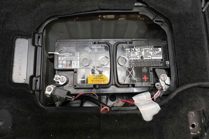
12V battery power can also be found in the cabin at the vehicle battery, located under the
passenger seat. On V6 models with Stop/Start, the larger battery is used for cranking the engine
and the smaller auxiliary battery is used to maintain electrical loads while the engine is in an
Autostop.
Figure 8: Battery Under Passenger Seat (V8 model shown)
Dodge Durango Pursuit Upfitter Guide 1212V battery power can also be found underhood at the remote jump start post, as shown in the
figures below.
Figure 9: Underhood Jump Start Post
Figure 10: Positive and Negative Jump Start Posts
Dodge Durango Pursuit Upfitter Guide 13For permanently mounted aftermarket equipment, the power sources shown above are
recommended. For portable equipment, ignition circuits can be found at 2 aux power outlets in
the cabin, which are each rated for 13A for customer use. They can be used to drive low power
loads as long as each does not exceed the rated current draw. The aux power outlets are
located:
1. To the left of the glovebox (powered with ignition on)
2. In the center console (powered from the battery), only with optional full size console
3. In the rear cargo area, it is set up from the factory to be powered with ignition on, but
by changing a fuse position in the underhood power distribution center (PDC) it can be
changed to battery powered (see fuse F90/F91).
Ignition circuits underhood can be found at the IGN relays in the PDC, though it is
recommended that splicing into PDC circuits be avoided to avoid disruption to factory installed
vehicle electrical systems. If IGN relays are utilized, it is recommended to use K03, K20, and K24
which are already dedicated for aftermarket equipment and feed the ignition circuits in the
VSIM 12-way jumper.
Multiple grounding locations can be found and are visible underhood. In the cabin, grounding
locations can be found behind trim in the following locations:
1. Under the center console
2. At the vehicle battery under the passenger seat
3. Adjacent to the rear wheel wells, driver’s and passenger’s sides
See the figures on the following pages for ground locations.
Dodge Durango Pursuit Upfitter Guide 14Figure 11: Center Console Grounding Locations Dodge Durango Pursuit Upfitter Guide 15
Figure 12: Driver’s Side C-Pillar Ground Location
                                  (Passenger Side Similar)

Dodge Durango Pursuit Upfitter Guide                                      16
Figure 13: Passenger’s Side D-Pillar Ground Location
(Driver’s Side Similar)
Dodge Durango Pursuit Upfitter Guide 17Figure 14: Cargo Area Grounding Locations Dodge Durango Pursuit Upfitter Guide 18
Pass Through Circuits

There are (6) unused 18 gauge wires available to the upfitter that are blunt cut in the
underhood area near the power distribution center (PDC) with the other end terminated in the
12-way upfitter connector with the VSIM jumpers. See the VSIM section for more information.
These wires are the preferred method to get power/signal circuits for aftermarket equipment
between the underhood area and the vehicle interior.

In the event additional capacity is necessary, many models have a pre-stamped hole through
the front of dash that can be used for passing through additional wires for customer use. The
hole is currently sealed with a grommet, and must be fully weather sealed if any wires are
passed through.

                             Figure 15: Pass Through Grommet
  (view from above in engine compartment, looking down in area behind the positive jump
                                         start post)

Dodge Durango Pursuit Upfitter Guide                                                            19
Figure 16: Pass Through Grommet
(view from passenger foot well area with trim removed)
Dodge Durango Pursuit Upfitter Guide 20VEHICLE SYSTEMS INTERFACE MODULE (VSIM)
VSIM Upfitter connector location
Figure 17: VSIM Upfitter Connectors
The VSIM upfitter connectors are in the right front underfloor bin in the cargo area.
Dodge Durango Pursuit Upfitter Guide 21Underhood pass-through circuits
Figure 18: Underhood pass-through circuits location (6 circuits total)
Dodge Durango Pursuit Upfitter Guide 22Figure 19: VSIM
The microcontroller-based electronic Vehicle Systems Interface Module (VSIM) is located on the
forward facing surface of the rear cargo bin immediately behind the right hand side 2nd row
seat. The VSIM contains the electronic logic circuitry and software that enable many of the
aftermarket equipment and systems typically installed on police or fleet vehicles to
communicate with and be integrated with the electronic control modules and features already
installed in the vehicle. It can communicate with aftermarket modules or with other electronic
modules in the vehicle using the Controller Area Network (CAN) data bus.
The VSIM awakens or sleeps based upon the status of the CAN data bus network. The module
monitors both active and stored Diagnostic Trouble Codes (DTC) through On-Board Diagnostics
(OBD) and communicates with a diagnostic scan tool using the CAN data bus.
Upfitter CAN bus
The VSIM upfitter J1939 CAN bus (cavities 11 and 12 in the VSIM 24-way upfitter C2 connector)
supports the following signals in addition to many industry standard J1939 signals:
Table 3: VSIM CAN Output Signals
Signals provided by the VSIM to indicate current operating conditions
Data Format Signal Note
Boolean Park Brake Applied
Boolean Brake Pedal Applied
Boolean A/C Turned On
Raw data Throttle Position %
Enumerated Shifter Position
Boolean FL Door Ajar
Boolean FR Door Ajar
Boolean RL Door Ajar
Boolean RR Door Ajar
Boolean Any Front Door Ajar
Boolean Any Back Door Ajar
Boolean Liftgate Ajar
Boolean Park Lamps On (manual or auto)
Boolean Low Beams On (manual or auto)
Boolean Cluster is Dimmed
Boolean High Beam Lever Selected On
Boolean RT Turn Signal On
Boolean LT Turn Signal On
Dodge Durango Pursuit Upfitter Guide 23Data Format Signal Note
Boolean Hazard Lights On
Boolean IGN Switch OFF
Boolean IGN Switch ACC
Boolean IGN Switch RUN/CRANK
Boolean Driver Seatbelt Status
Boolean Passenger Seatbelt Status
Boolean Horn Button is Pressed
Boolean Stealth Mode Active
Boolean Secure Park Active
Boolean Vehicle Securement Triggered
Boolean AUX Output 1 Status
Boolean AUX Output 2 Status
Boolean AUX Output 3 Status
Boolean AUX Output 4 Status
Raw data Vehicle Speed
Boolean Vehicle Speed is above 30MPH
Raw data Fuel Level %
Boolean A/C Clutch Engaged
Raw data Engine RPM
Boolean Transmission in Park
Boolean Transmission in Reverse
Boolean Transmission in Neutral
Boolean Transmission in Drive or any Forward Gear
Boolean Engine is Running
Enumerated IGN Switch Position
Boolean MIL is Active
Raw data Oil Life %
Raw data Odometer
Raw data Engine Hours
Raw data Idle Hours
Note: Not all signals are available in all applications.
Table 4: VSIM CAN Input Signals
Signals that aftermarket equipment sends to the VSIM to request action
Data Format Signal Note
Boolean Activate Front Wigwag Front wigwag only stays active while signal is
set
Boolean Activate Rear Wigwag Rear wigwag only stays active while signal is
set
Boolean Mute Entertainment Audio Mute only stays active while signal is set
Boolean Activate Stealth Mode Stealth mode only stays active while signal is
set
Boolean Activate Secure Park Secure park activates on rising edge of this
signal; does not require signal to be set
continuously
Boolean Deactivate Secure Park Secure park deactivates on rising edge of this
signal (with valid FOB present); does not
require signal to be set continuously
Boolean Temporarily Suppress Forward Collision FCW/AEB only stays suppressed while signal is
Warning/Automatic Emergency Braking set; return to previous customer setting when
(FCW/AEB) not set
Boolean Activate AUX output 1 Output only stays active while signal is set
Boolean Activate AUX output 2 Output only stays active while signal is set
Dodge Durango Pursuit Upfitter Guide 24Data Format Signal Note
Boolean Activate AUX output 3 Output only stays active while signal is set
Boolean Activate AUX output 4 Output only stays active while signal is set
Note: Not all signals are available in all applications.
The J1939 database for CAN (.dbc) file for these signals is available, use the contact info on the
fleet website to request it for your application.
Dodge Durango Pursuit Upfitter Guide 2512-way Upfitter connector
Figure 20: 12-way upfitter connector
Included mating jumper/pigtail 68251805AA (has 12-way gray connector)
Table 5: 12-way upfitter connector pinout
CAVITY SIGNAL TYPE USER DESCRIPTION CIRCUIT # COLOR
1 FUSED B(+) OUTPUT 20A battery feed A100 RD / VT
2 FUSED B(+) OUTPUT 20A battery feed A101 VT / RD
3 FUSED B(+) OUTPUT 20A battery feed A102 WH / RD
4 IGN FEED - RUN OUTPUT 20A IGN feed active in RUN (engine F105 PK
running or not running). Drops out in
CRANK, but stays active in an engine
stop-start (ESS) CRANK.
5 IGN FEED - RUN OUTPUT 20A IGN feed active in RUN (engine F103 PK / GY
running or not running). Drops out in
CRANK, but stays active in an engine
stop-start (ESS) CRANK.
6 IGN FEED - RUN OUTPUT 20A IGN feed active in RUN (engine F102 PK / DB
running or not running). Drops out in
CRANK, but stays active in an engine
stop-start (ESS) CRANK.
7 PASS THROUGH (18 GAUGE) SPARE Pass-through to underhood blunt-cut Z384 BK
bundle
8 PASS THROUGH (18 GAUGE) SPARE Pass-through to underhood blunt-cut P239 GN / WH
bundle
9 PASS THROUGH (18 GAUGE) SPARE Pass-through to underhood blunt-cut P820 BN / OG
bundle
10 PASS THROUGH (18 GAUGE) SPARE Pass-through to underhood blunt-cut P822 BN / WH
bundle
11 PASS THROUGH (18 GAUGE) SPARE Pass-through to underhood blunt-cut W507 OG
bundle
12 PASS THROUGH (18 GAUGE) SPARE Pass-through to underhood blunt-cut W508 OG / BN
bundle
NOTE: The 12-way connector is located in the underfloor bin along with the (2) 24-way VSIM
upfitter connectors. The opposite end of the 18 gauge pass-through circuits in cavities 7-
12 of the 12-way connector can be found bundled as blunt cut wires near the
underhood power distribution center, see figure 18.
Dodge Durango Pursuit Upfitter Guide 2624-way Upfitter C1 connector (gray)
Figure 21: VSIM 24-way upfitter C1 connector
Included mating jumper/pigtail 68518169AA (has 24-way gray connector)
Table 6: VSIM 24-way upfitter C1 Connector Pinout
CAVITY SIGNAL TYPE USER DESCRIPTION CIRCUIT # COLOR
1 AUX 1 OUTPUT OUTPUT Get 12V max 500mA when AUX1 W561 GN / BN
output is active
2 AUX 2 OUTPUT OUTPUT Get 12V max 500mA when AUX2 W562 GN / VT
output is active
3 FORWARD COLLISION INPUT Apply 12V to suppress FCW/AEB (if W727 GN / OG
WARNING/AUTOMATIC EMERGENCY equipped), remove voltage to restore
BRAKING SUPPRESS (FCW/AEB) prior state of FCW/AEB
4 NO CONNECT
5 SECURE PARK ENABLE INPUT Apply 12V to activate secure park. W729 GN / YE
Activation only occurs on a rising
edge (must remove voltage and
reapply to activate secure park
again). No secure park deactivation is
possible through this input.
6 NO CONNECT
7 NO CONNECT
8 AUX 3 OUTPUT OUTPUT Get 12V max 500mA when AUX3 W563 GN / DB
output is active
9 IGNITION ACC SIGNAL OUTPUT Get GND when IGN is in ACC (or IGN W734 PK / GY
passes through ACC)
10 IGNITION RUN SIGNAL OUTPUT Get GND when IGN is in RUN (engine W736 PK / YE
running or not running). GND drops
out in CRANK.
11 ANY DOOR AJAR SIGNAL OUTPUT Get GND when any passenger door is W720 VT / OG
ajar or open (does not include
liftgate)
12 RIGHT FRONT DOOR AJAR OUTPUT Get GND when right front passenger G745 VT / DB
door is ajar or open
13 RIGHT REAR DOOR AJAR OUTPUT Get GND when right rear passenger G776 VT / OG
door is ajar or open
14 NO CONNECT
15 NO CONNECT
16 NO CONNECT
Dodge Durango Pursuit Upfitter Guide 27CAVITY SIGNAL TYPE USER DESCRIPTION CIRCUIT # COLOR
17 NO CONNECT
18 NO CONNECT
19 LEFT REAR DOOR AJAR OUTPUT Get GND when left rear passenger G755 VT / BG
door is ajar or open
20 INTERIOR LIGHTS DIMMED OUTPUT Get 12V max 500mA when the W521 OG / GY
interior lights are at any dimming
level (not full bright, not stealth)
21 TRANS REVERSE SIGNAL OUTPUT Get GND when trans is in Reverse W702 DG / DB
22 TRANS DRIVE SIGNAL OUTPUT Get GND when trans is in Drive W703 DG / BU
23 AUX 4 OUTPUT OUTPUT Get 12V max 500mA when AUX4 W564 DB
output is active
24 NO CONNECT
NOTE: The 12V and GND signals provided by the VSIM are low current I/O intended only to
drive very small loads (such as an automotive relay) or provide input signals to your
aftermarket equipment. For sourcing or sinking higher current, use the 20A circuits
provided in the 12-way connector and the ground terminals described within this guide.
Dodge Durango Pursuit Upfitter Guide 2824-way Upfitter C2 connector (white)
Figure 22: VSIM 24-way upfitter C2 connector
Included mating jumper/pigtail: 68251804AA (has 24-way white connector)
Table 7: VSIM 24-way upfitter C2 connector pinout
CAVITY SIGNAL TYPE USER DESCRIPTION CIRCUIT # COLOR
1 FRONT WIGWAG INPUT Apply 12V to activate lamps W500 BN / OG
2 REAR WIGWAG INPUT Apply 12V to activate lamps W501 BN / VT
3 RADIO MUTE INPUT Apply 12V to mute entertainment W640 GY / DG
audio
4 BRAKE PEDAL SIGNAL OUTPUT Get 12V max 250mA when brake W726 DG / OG
pedal pressed
5 HORN PAD SENSE OUTPUT Get 12V max 500mA when horn pad W513 BN / GY
pressed
6 TRANS PARK SIGNAL OUTPUT Get 12V max 500mA when in Park W700 YE / DB
7 SECURITY ALARM ON SIGNAL OUTPUT Get 12V max 500mA when vehicle W515 VT / BU
theft alarm or Panic is alarming
8 HEADLAMP ON SIGNAL OUTPUT Get 12V max 500mA when headlamps W516 BN / DB
are on (manual or auto)
9 LOW VEHICLE SPEED OUTPUT Get 12V max 500mA when vehicle W524 BN / YE
speed is below 30mph (48kmh)
10 STEALTH MODE ACTIVE OUTPUT Get 12V max 500mA when stealth W553 GN
mode is active
11 CAN J1939 (+) CAN Upfitter bus + W532 BN / DB
12 CAN J1939 (-) CAN Upfitter bus - W534 BN / BU
13 CLUSTER DIMMING SIGNAL OUTPUT Pulse width modulated (PWM) output W552 OG / WH
proportional to level of cluster
dimming
14 ENGINE RUNNING STATUS OUTPUT Get 12V max 500mA when engine is W522 DB / BG
running
15 LEFT FRONT DOOR AJAR OUTPUT Get 12V max 1000mA when driver W523 BN / GY
door is ajar or open
16 GROUND INPUT Z910 BK
17 SECURE PARK ACTIVE OUTPUT Get 12V max 500mA when secure W745 VT / BG
park is active
18 NO CONNECT
19 VEHICLE SPEED SIGNAL OUTPUT Square wave: 10Hz per mph, at 50% W526 BN / DB
duty cycle
Dodge Durango Pursuit Upfitter Guide 29CAVITY SIGNAL TYPE USER DESCRIPTION CIRCUIT # COLOR
20 HORN MUTE INPUT Apply 12V to mute horn (only horn W536 GY / DB
via horn pad press is muted, not
remote keyless chirps, etc.)
21 SECURITY ALARM MUTE INPUT Apply 12V to mute panic or vehicle W537 DB / YE
theft alarm (if equipped)
22 NO CONNECT
23 LEFT FRONT SEAT BELT SWITCH OUTPUT Get 12V max 250mA when driver's W710 GN / VT
SENSE seat belt is unbuckled
24 MIL ILLUMINATED OUTPUT Get 12V max 500mA when engine W540 DG
MIL is on (including non-fault
conditions such as IGN ON with ENG
OFF)
NOTE: The 12V and GND signals provided by the VSIM are low current I/O intended only to
drive very small loads (such as an automotive relay) or provide input signals to your
aftermarket equipment. For sourcing or sinking higher current, use the 20A circuits
provided in the 12-way connector and the ground terminals described within this guide.
Dodge Durango Pursuit Upfitter Guide 30FLEET SETTINGS MENU
The instrument cluster has a fleet settings menu to allow customization of certain police and
VSIM related features. The arrow keys and OK button on the left side of the steering wheel are
used to navigate into and around the menu and make selections.
Push and release the up or down arrow button until the Fleet Settings Menu icon/title is
highlighted in the instrument cluster display. Push the left or right arrow button to scroll
through the information submenus.
PIN Setup
The factory default PIN is 0000. It is important to set a personalized 4 digit PIN to deter
anyone from making unwanted changes to the vehicle's fleet and security settings. Whether
you set the same PIN for all vehicles in the fleet or individual PINs for each vehicle, set a
PIN. If the PIN is lost, it can be reset by a dealer.
AUX Switches
Type
Latching – remains active after button is pressed, press again to turn off
Momentary – active only while the button is held down
Off at Ignition Off
Durango Pursuit AUX switches turn off when the ignition is turned off.
Set to Yes if the "Last State" feature (below) will be used
Last State
On – A latching AUX output will remember it’s previous state on new ignition cycles
Off – The AUX output will reset to deactivated on each new ignition cycle
Note: Customization can be made for 4 AUX outputs. Even if the vehicle only has 3 switches in
the integrated center stack switch bank, the AUX 4 output is still available to control via
the VSIM upfitter CAN bus. See the VSIM section for more information.
Lockout Prevention
Enabled / Disabled – Refer to the FOBIK-safe feature in Owner’s Manual
FOB Chime
Enabled / Disabled – “FOB has left the vehicle” audible chime is enabled or disabled
Theft Alarm
Enabled / Disabled – Vehicle must be equipped with vehicle theft alarm (sales code LSA)
Panic Alarm
Enabled / Disabled – PANIC button on key FOB is enabled or disabled
Dodge Durango Pursuit Upfitter Guide 31Secure Park
Activation
Manual – The center buttons on either side of the back of the steering wheel will
activate Secure Park.
Auto – Secure Park is activated every time the vehicle is in Park, the driver’s door is
open, and the brake pedal is not pressed. It can also be activated manually.
Disabled – Secure Park is disabled on the vehicle. The center buttons on the back of the
steering wheel become inoperative.
Deactivation
Manual – The center buttons on either side of the back of the steering wheel will
deactivate Secure Park. If Auto Secure Park Activation is selected above, the driver's
door must be closed and/or brake pedal applied to manually deactivate Secure Park. A
valid FOB must be present to deactivate.
Auto – The vehicle will attempt to deactivate Secure Park every time the system is
active, in Park, and the brake pedal is pressed. A valid FOB must be present to
deactivate.
Note: The VSIM upfitter CAN bus may be used to activate or deactivate Secure Park. There is
also a hardwired input available to activate Secure Park. See the VSIM section for more
information.
Liftgate Release
Interior Release – Vehicle must be equipped with power liftgate (sales code JRC)
Ignition Only – The interior release button will only function if the ignition is in the RUN
position.
Unlocked Vehicle – The interior release button will operate unless the vehicle theft
alarm (sales code LSA) is equipped on the vehicle and armed.
Unlock with Doors – This setting applies for either manual or power liftgate
Enabled – The liftgate can be opened from the passive entry handle on the liftgate of
the vehicle anytime the vehicle passenger doors are unlocked.
Disabled – The liftgate can only be opened from the passive entry handle on the liftgate
if there is a FOB at the rear of the vehicle within approximately three feet of the liftgate,
or by pressing the liftgate button 2x on the FOB to unlock (manual liftgate) or open
(power liftgate).
VSIM Timeout
VSIM timeout is managed automatically on Pursuit models and no adjustments are available
or necessary.
Dodge Durango Pursuit Upfitter Guide 32LIGHTING
Police Dome Lamps
Figure 23: Police Dome Lamp (front shown)
The Durango Pursuit is equipped with 2 police dome lamps. The dome lamp switch has three
positions. One side of the switch turns on white LED lights, the other side turns on red LED
lights, and the center position turns the lamp OFF. The dome lamps will work with the ignition
on or if the courtesy lamp circuit is energized. Always remember to return the dome light
switch to the OFF (center) position to prevent the vehicle battery from discharging.
Dodge Durango Pursuit Upfitter Guide 33Spot Lamp(s)
Figure 24: Spot Lamp
Mopar LED spot lamp(s) (optional) are recommended and are installed before vehicle delivery.
If you choose to install your own spot lamp(s), you can find electrical connectors at the forward
edge of the headliner near the A-pillars, see the figure below. There are electrical connectors
on both driver and passenger sides, and they are battery fed through a pair of 15A fuses in the
underhood PDC.
CAUTION: The side curtain airbag is tethered in the area of the spot lamp. If drilling and
installing your own lamp, make sure the tether is not damaged during the install
and is properly reattached when the installation is complete.
Dodge Durango Pursuit Upfitter Guide 34Figure 25: Spot Lamp Power Connector Taped Back Above Headliner Dodge Durango Pursuit Upfitter Guide 35
EQUIPMENT MOUNTING PLATE

                            Figure 26: Equipment Mounting Plate

The equipment mounting plate, if equipped, is designed to allow aftermarket equipment to be
secured between the front seats. Remove the 4 bolts and remove the plate from the vehicle
before cutting the plate or drilling holes. There are some electronics and wiring beneath the
plate, be sure to confirm that once equipment is mounted that any fasteners will be clear of
these electronics. The “No Drill” area marked on the plate denotes the area below which the
most electronics are located and the greatest care should be taken to ensure any fasteners will
not protrude too far below the plate.

Dodge Durango Pursuit Upfitter Guide                                                         36
USB MEDIA HUB REMOVAL
Figures 27A-B: Media Hub Removal
If the USB media hub is to be removed from the mini console during the upfit process, use
1-1.5mm shim stock to get between the media hub and the mini console housing. Push on the
snaps and slide the shims over the 4 snap holes as shown. Once the shims cover all the holes,
the USB hub can be rocked out of the console without damage.
Dodge Durango Pursuit Upfitter Guide 37RESTRAINTS
Occupant Restraint System Overview
WARNING: INSTALLING A CONVENTIONAL PRISONER PARTITION IS NOT RECOMMENDED
ON VEHICLES EQUIPPED WITH LEFT AND RIGHT SIDE CURTAIN AIRBAGS, AS
POLICE CAGES MAY INTERFERE WITH THE DEPLOYING AIRBAG. THE AREA
WHERE THE SIDE CURTAIN AIRBAG IS LOCATED SHOULD REMAIN FREE FROM
ANY OBSTRUCTIONS. ONLY INSTALL A PARTITION THAT IS DESIGNED TO BE
COMPATIBLE WITH SIDE CURTAIN AIRBAGS.
WARNING: YOUR VEHICLE IS EQUIPPED WITH LEFT AND RIGHT SIDE CURTAIN AIRBAGS,
AND CARE MUST BE TAKEN WHEN INSTALLING ANY TYPE OF ROOF
EQUIPMENT. DRILLING AND INSTLALLATION OF FASTENERS OR OTHER
EQUIPMENT THAT MAY INTERFERE WITH THE SIDE CURTAIN AIRBAGS AND
AIRBAG WIRING HARNESSES IS NOT PERMITTED. MAKE SURE THAT NO
EQUIPMENT OR FASTENERS ARE LOCATED IN THE AIRBAG DEPLOYMENT ZONE.
WARNING: DO NOT PLACE OBJECTS, OR MOUNT EQUIPMENT, IN FRONT OF THE AIRBAG
MODULE COVER OR IN FRONT OF THE SEAT AREAS THAT MAY COME IN
CONTACT WITH A DEPLOYING AIRBAG. FAILURE TO FOLLOW THIS
INSTRUCTION COULD RESULT IN PERSONAL INJURY.
WARNING: DO NO PLACE DASH, TUNNEL, OR CONSOLE-MOUNTED EQUIPMENT OUTSIDE
OF THE SPECIFIED ZONE. FAILURE TO FOLLOW THIS INSTRUCTION COULD
RESULT IN PERSONAL INJURY.
The occupant restraint system contains the following components:
Occupant restraint controller (ORC) module
Front and side impact sensors
Seatbelt pretensioners
Seat track position sensors
Occupant classification system
Driver and passenger side knee impact bolsters
Airbags:
o Driver airbag
o Driver side (seat mounted) airbag
o Driver side curtain airbag
o Supplemental driver knee airbag
o Passenger airbag
o Passenger side (seat mounted) airbag
o Passenger side curtain airbag
There are four interior zones to be aware of:
Driver airbag deployment zone
Passenger airbag deployment zone
Dodge Durango Pursuit Upfitter Guide 38 Side curtain airbag deployment zone
Side airbags (seat-mounted) deployment zone
Driver Airbag (DAB) Deployment Zone
1 Vertical Plane Passing Through the Center of the 4 Steering Wheel
Steering Wheel
2 470 mm (18.5 in.) 5 Driver Airbag Retainer/Housing
3 Vertical Plane Passing Through the Maximum Rearward 6 Driver Airbag Cushion
Point that the Driver Airbag Cushion Reaches
Figure 28: Driver Airbag Dimensions
NOTE: The illustration represents the maximum dynamic deployment shape.
Table 8: Driver Airbag Cushion Position
DAB (Driver Airbag) diameter when full 673 mm (26.5 in.)
DAB depth when full 381 mm (15 in.)
Maximum rearward displacement during fill 470 mm (18.5 in.)
Dodge Durango Pursuit Upfitter Guide 39Figure 29: Driver Airbag Deployed Shape
Table 9: Steering Column Tilt Position Range
±2.5 degrees from steering column tilt pivot point
22.0 degrees from vertical is the normal position
Dodge Durango Pursuit Upfitter Guide 401 Driver Seating Reference 2 Driver Airbag Cushion Lateral Deployment Zone
711mm (28 in.)
Figure 30: Deployment Zone
Dodge Durango Pursuit Upfitter Guide 411 Passenger Airbag Cushion 4 Instrument Panel Surface
2 Vertical Plane from Rearmost Point of 5 Vertical Plane Passing Through the
Instrument Panel Maximum Rearward Point That the
Passenger Airbag Cushion Reaches
3 Passenger Airbag Module 6 450 mm (17.7 in.)
Figure 31: Passenger Airbag Deployment Zone
NOTE: The illustration represents the maximum dynamic deployment shape.
Dodge Durango Pursuit Upfitter Guide 42Figure 32: Final Deployment Shape Dodge Durango Pursuit Upfitter Guide 43
1   577 mm (22.7 in.)                       3 87 mm (3.4 in.)
  2   Passenger Airbag Deployment Zone        4 Reference Point
                              Figure 33: Deployment Zone

Dodge Durango Pursuit Upfitter Guide                              44
Figure 34: Center Interior Area
WARNING: MAKE SURE ADEQUATE SPACE IS AVAILABLE FOR AIRBAG DEPLOYMENT.
MOUNTING ACCESSORIES AND EQUIPMENT INSIDE THE DEPLOYMENT
ZONES IMPEDES AIRBAG DEPLOYMENT.
NOTE: The illustration represents the maximum dynamic deployment shape.
Dodge Durango Pursuit Upfitter Guide 45Side Curtain Airbag Deployment Zone
Figure 35: Side Curtain Airbag Deployment Zone
Dodge Durango Pursuit Upfitter Guide 46Figure 36: Side Curtain Airbag Deployment Zone
Table 10: Side Airbag Deployment Zone Reference Chart
Callout Millimeters Inches
1 2071 81.5
2 1824 71.8
3 600 23.6
4 1961 77.2
5 1666 65.6
6 589 23.2
7 220.8 8.7
8 84 3.3
9 114.8 4.5
10 Inflator
11 B-Pillar
12 475.83 18.7
13 593.32 23.4
14 967.4 38.1
15 993.6 39.1
16 118.49 4.7
WARNING: MAKE SURE ADEQUATE SPACE IS AVAILABLE FOR AIRBAG
DEPLOYMENT. DO NOT MOUNT EQUIPMENT OR ROUTE WIRES IN A
WAY THAT WILL IMPEDE SIDE CURTAIN AIRBAG DEPLOYMENT.
Dodge Durango Pursuit Upfitter Guide 47Side Airbag Deployment Zone
1 Front Driver Seat 4 1998.9 mm (78.7 in.)
2 4495.8 mm (177 in.) 5 Seat-mounted Airbag
3 1998.9 mm (78.7 in.)
Figure 37: Side Seat-mounted Airbag Deployment Zone
NOTE: The illustration represents the maximum dynamic deployment shape.
Use caution when installing equipment along the roof side rails to avoid drilling or installing
fasteners in the side curtain airbag area. Also make sure that no equipment interferes with the
airbag deployment areas.
If additional wiring needs to be routed on the sides of the roof, take care that the installed
harness does not impede the airbag deployment. Point fasteners used to attach roof-mounted
equipment outward from the passenger compartment to minimize risk of head injury and to
avoid altering the head impact protection system (FMVSS 201) that is standard on these
vehicles. Do not allow fasteners to extend into the passenger compartment, even between the
roof and headliner.
CAUTION: It is imperative that all occupant restraint system components remain in their
original location and orientation. Any modification, removal, or relocation of
components may be detrimental to the occupant restraint system performance
and is prohibited. Any vehicle modifications that may affect the occupant
restraint system characteristics should be verified through vehicle
calibration/impact testing.
Dodge Durango Pursuit Upfitter Guide 48Occupant Restraint System Wiring All occupant restraint system wiring must remain intact and may not be used for any other purpose. This includes the driver and front passenger seat wiring. Any electrical connector that is yellow is part of the occupant restraint system and should not be modified or used for other purposes. Occupant Restraint System Verification After any modification work is complete, confirm the occupant restraint system readiness as follows: turn the ignition key to the ON position. The airbag lamp in the instrument cluster illuminates for 6 to 8 seconds, and then turns off. If the airbag lamp fails to illuminate, repeatedly cycles on and off, or does not turn off, have the condition corrected by an authorized dealership before shipping the vehicle to the customer. Dodge Durango Pursuit Upfitter Guide 49
VEHICLE STORAGE
General Storage Recommendations
If a vehicle is not immediately delivered to the customer, store the vehicle according to the
following guidelines:
Store the vehicle indoors, in a clean and dry place.
Check the engine coolant and anti-freeze protection.
Leave the parking brake in the OFF position
Check the vehicle tire pressures and inflate them to the maximum recommended levels. To
help avoid flat spotting, move the vehicle at least once a month so that a different portion
of the tire tread contacts the ground
If vehicles must be stored outside:
Avoid storage locations near obvious sources of industrial or environmental contamination
(such as trees, factories, steam or vapor vents, railroad tracks, etc.).
Maintain tight security to help prevent vandalism. Inspect the vehicle regularly to check for
such damage.
If the vehicle must be parked on an incline, park it with the front end higher than the rear.
This prevents hydrostatic lock caused by fuel draining into the engine.
Rinse the vehicle at least once a week. Wash away the snow more often because it can trap
harmful contaminants. Dry all horizontal surfaces.
Remove the negative battery cable by removing the ground connection nut to prevent
battery drain and possible damage.
Keep all windows closed, all doors locked, and all trim covers intact and in place.
Do not use chalk, crayon, or any marker containing abrasives on painted, plated, or glass
surfaces.
Use protective, thin, plastic film to avoid soiling seats when moving a vehicle.
Dodge Durango Pursuit Upfitter Guide 50Battery Maintenance
The Dodge Durango Pursuit vehicle does not have an ignition off draw (IOD) fuse as in some
other models. Therefore, the negative battery cable should be removed from the intelligent
battery sensor to prevent draining the battery during extended vehicle storage. Only loosen the
ground connection nut from the intelligent battery sensor to remove the negative battery
cable.
WARNING: THE BATTERY IN THIS VEHICLE HAS A VENT HOSE THAT SHOULD NOT BE
DISCONNECTED AND SHOULD ONLY BE REPLACED WITH A BATTERY OF THE
SAME TYPE (VENTED). FAILURE TO FOLLOW THIS WARNING CAN RESULT IN
SERIOUS OR FATAL INJURY.
Once a month:
Check the battery state for charge (at least 12.4 volts). Charge the battery as necessary to
help prevent freezing and deterioration.
Make sure that the battery vent tube is properly connected to the battery and to the floor
pan.
Figure 38: Intelligent Battery Sensor
Dodge Durango Pursuit Upfitter Guide 51Shipping Mode The Dodge Durango Pursuit body control module has a Shipping Mode for transporting or storing for a long period of time, and for the time between when the vehicle leaves the factory and is ready for use by the customer. The vehicle will come from the factory in Shipping mode. Turn the hazard lamps on and press/hold the up arrow on the steering wheel electronic vehicle information center (EVIC) controls until the vehicle enters or exits shipping mode. Note that this procedure is only possible while the vehicle has relatively low mileage. If the procedure fails, threshold mileage has most likely been exceeded. You can also enable/disable the vehicle from Shipping Mode by using the scan tool: go to BCM then Misc. functions. In all cases, if shipping mode is no longer available for a vehicle, to reduce battery drain follow the battery disconnection recommendation described in the battery maintenance section above. Dodge Durango Pursuit Upfitter Guide 52
Notes:

Dodge Durango Pursuit Upfitter Guide   53
The special service tools referred to herein are required for certain service operations. These
 special service tools or their equivalent, if not obtainable through a local source, are
 available through the following outlet:

                                 Telephone 1-855-298-2687
                          2801-80th Street Kenosha, WI 53143, U.S.A.
                                     FAX 1-855-303-8985

Dodge Durango Pursuit Upfitter Guide                                                           54
No part of this publication may be reproduced, stored in a retrieval
system or transmitted, in any form or by any means, electronic,
mechanical, photocopying, recording, or otherwise, without the prior
written permission of Stellantis.
Stellantis reserves the right to make changes from time to time,
without notice or obligation, in prices, specifications, colors and
materials, and to change or discontinue models. See your dealer for
the latest information.
Copyright © 2021 Stellantis
Upfitter Guide Revision 3/5/2021
Dodge Durango Pursuit Upfitter Guide 55You can also read