DokaTruss table User Information - Instructions for assembly and use
←
→
Page content transcription
If your browser does not render page correctly, please read the page content below
999810914 - 05/2021
en-US

The Formwork Experts.

DokaTruss table
User Information
Instructions for assembly and use
© by Doka GmbH, A-3300 Amstetten

                                                   © by Doka GmbH, A-3300 Amstetten

                                    98109-201-01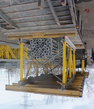
User Information DokaTruss table

2   999810914 - 05/2021
User Information DokaTruss table

Contents
   4      Introduction
   4      Basic safety warnings
   7      Services

   9      System description
  10      System overview
  13      System dimensions
  18      Instructions for assembly and use
  21      Adaptation to building layout
  29      Height adjustment
  30      Drop beams
  31      Slab bulkheads
  33      Fall protection on the formwork

  34      Structural design

  38      Repositioning
  38      General instructions on repositioning
  39      Lowering
  40      Horizontal traveling
  42      Vertical repositioning by crane
  43      Repositioning operation
  47      Lining and leveling DokaTruss tables

  49      Assembly

  55      General remarks
  55      Combining with other Doka systems
  56      Transporting, stacking and storing
  63      Fall protection on the structure
  64      Reshoring props, concrete technology and
          stripping

  68      Article list

               999810914 - 05/2021                   3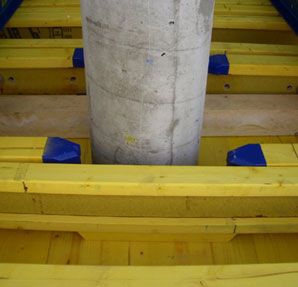
Introduction                                                                                 User Information DokaTruss table

Introduction
Basic safety warnings
User target groups                                              Remarks on this booklet
▪ This booklet is aimed at all persons who will be work-        ▪ This document can be used as general Instructions
    ing with the Doka product or system that it describes.          for Assembly and Use (Method Statement) or be
    It contains information on the standard design for              incorporated into site-specific Instructions for
    setting up this system, and on correct, compliant uti-          Assembly and Use (Method Statement).
    lization of the system.                                     ▪   The graphics, animations and videos in this doc-
▪   All persons working with the product described                  ument or app sometimes depict partially assem-
    herein must be familiar with the contents of this               bled assemblies and may require additional
    booklet and with all the safety instructions it contains.       safety equipment and/or measures to comply
▪   Persons who are incapable of reading and under-                 with safety regulations.
    standing this booklet, or who can do so only with dif-          The customer must ensure all applicable regulations
    ficulty, must be instructed and trained by the cus-             are complied with, even if they are not shown or
    tomer.                                                          implied in the graphics, animations and videos pro-
▪   The customer is to insure that the information mate-            vided.
    rials provided by Doka (e.g. User Information book-         ▪   Individual sections contain further safety
    lets, Method Statements, Operating Instruction man-             instructions and/or special warnings as applica-
    uals, plans etc.) are up to date and available to all           ble.
    users, and that users have been made aware of
    them and have easy access to them at the usage
    location.                                                   Planning
▪   In the relevant technical documentation and form-
    work utilization plans, Doka shows the workplace            ▪ Provide safe workplaces for those using the form-
    safety precautions that are necessary in order to use           work (e.g. for when it is being erected/dismantled,
    the Doka products safely in the usage situations                modified or repositioned etc). It must be possible to
    shown.                                                          get to and from these workplaces via safe access
    In all cases, users must ensure compliance with the             routes!
    national applicable laws, standards and rules               ▪   If you are considering any deviation from the
    throughout the entire project and to take appropriate           details and instructions given in this booklet, or
    additional or alternative workplace safety precau-              any application which goes beyond those
    tions where necessary.                                          described in the booklet, then revised static cal-
                                                                    culations must be produced for checking, as well
                                                                    as supplementary assembly instructions.
Hazard assessment
▪ The customer is responsible for drawing up, docu-             Regulations; occupational health &
    menting, implementing and continually updating a
    hazard assessment at every job-site.
                                                                safety
    This booklet serves as the basis for the site-specific
    hazard assessment, and for the instructions given to        ▪ All laws, Standards, industrial safety regulations and
    users on how to prepare and utilize the system. It              other safety rules applying to the application and uti-
    does not substitute for these, however.                         lization of our products in the country and/or region
                                                                    in which you are operating must be observed at all
                                                                    times.
                                                                ▪   If a person or object falls against, or into, the side-
                                                                    guard component and/or any of its accessories, the
                                                                    component affected may only continue in use after it
                                                                    has been inspected and passed by an expert.

4                                                                                         999810914 - 05/2021
User Information DokaTruss table Introduction
Rules applying during all phases of flying sparks do not heat and thus damage other tie
rods.
the assignment: Welding work can be done only on the articles
expressly mentioned in the Doka documents as
▪ The customer shall ensure that this product is being suitable for work of this nature.
erected and dismantled, repositioned and generally
used for its intended purpose in accordance with the
applicable laws, standards and rules, under the Assembly
direction and supervision of suitably skilled persons.
These persons' mental and physical capacity shall ▪ The equipment/system must be inspected by the
not in any way be impaired by alcohol, medicines or customer before use, to ensure that it is in suitable
drugs. condition. Steps must be taken to rule out the use of
▪ Doka products are technical working appliances components that are damaged, deformed, or weak-
which are intended for industrial / commercial use ened due to wear, corrosion or rot (e.g. fungal
only, always in accordance with the respective Doka decay).
User Information booklets or other technical docu- ▪ The use of our safety systems and formwork sys-
mentation authored by Doka. tems in combination with those of other manufactur-
▪ The stability and load-bearing capacity of all compo- ers could be dangerous, risking injury to health and
nents and units must be ensured during all phases of damage to property, and therefore requires separate
the construction work! verification by the user.
▪ Do not step on or apply strain to cantilevers, clo- ▪ The equipment/system must be assembled and
sures, etc. until suitable measures to ensure their erected in accordance with the applicable laws, stan-
stability have been correctly implemented (e.g. by dards and rules by suitably skilled personnel of the
tie-backs). customer's, having regard to any and all required
▪ The functional / technical instructions, safety warn- safety inspections.
ings and loading data shall all be strictly observed ▪ It is not permitted to modify Doka products; any such
and complied with. Non-compliance can cause acci- modifications constitute a safety risk.
dents and severe injury (risk of fatality) and serious
damage to property.
▪ Sources of fire in the vicinity of the formwork are pro- Erecting the formwork
hibited. Heaters are permissible only when used cor-
rectly and situated a correspondingly safe distance ▪ Doka products and systems must be set up in such
from the formwork. a way that all loads acting upon them are safely
▪ Customer must give due consideration to any and all transferred!
effects of the weather on the equipment and regards
both its use and storage (e.g. slippery surfaces, risk
of slipping, effects of the wind, etc.) and implement Pouring
appropriate precautionary measures to secure the
equipment and surrounding areas and to protect
workers.
▪ Do not exceed the permitted fresh-concrete pres-
sures. Excessively high pouring rates lead to form-
▪ All connections must be checked at regular intervals work overload, cause greater deflection and risk
to ensure that they are secure and in full working causing breakage.
order.
In particular threaded connections and wedged con-
nections have to be checked and retightened as nec- Stripping the formwork
essary in accordance with activity on the jobsite and
especially after out-of-the-ordinary occurrences (e.g.
after a storm). ▪ Do not strip the formwork until the concrete has
reached sufficient strength and the person in charge
▪ It is strictly prohibited to weld or heat Doka products,
has given the order for the formwork to be stripped!
particularly parts for anchoring, suspension or con-
necting, and also cast parts, etc. ▪ When stripping the formwork, never use the crane to
break concrete cohesion. Use suitable tools such as
Welding radically changes the micro-structure of the
timber wedges, special pry-bars or system features
materials of which these components are made. This
such as Framax S bias-cut corners.
leads to a drastic reduction in failure load, constitut-
ing a serious safety risk. ▪ When stripping the formwork, do not endanger the
stability of any part of the structure, or of any scaf-
It is permissible to cut individual tie rods to length
folding, platforms or formwork that is still in place!
with metal cutting discs (introduction of heat at the
end of the rod only), but it is important to ensure that
999810914 - 05/2021 5Introduction User Information DokaTruss table
Transporting, stacking and storing Symbols
▪ Observe all country-specific regulations applying to The following symbols are used in this document:
the handling of formwork and scaffolding. For system
formwork the Doka slinging means stated in this DANGER
booklet must be used – this is a mandatory require- This is a notifier drawing attention to an
ment. extremely dangerous situation in which non-
If the type of sling is not specified in this booklet, the compliance with this notifier will lead to death
customer must use slinging means that are suitable or severe, irreversible injury.
for the application envisaged and that comply with
the regulations.
▪ When lifting, always make sure that the unit to be WARNING
lifted and its individual parts can absorb the forces This is a notifier drawing attention to a dan-
that occur. gerous situation in which non-compliance
▪ Remove loose parts or secure them so that they can- with this notifier can lead to death or severe,
not slip out of position and drop. irreversible injury.
▪ When lifting formwork or formwork accessories with
a crane, no persons must be carried along, e.g. on
working platforms or in multi-trip packaging. CAUTION
▪ All components must be stored safely, following all This is a notifier drawing attention to a dan-
the special Doka instructions given in the relevant gerous situation in which non-compliance
sections of this document! with this notifier can lead to slight, reversible
injury.
Maintenance
NOTE
▪ Only original Doka components may be used as This is a notifier drawing attention to a situa-
spare parts. Repairs may only be carried out by the
tion in which non-compliance with this noti-
manufacturer or authorized facilities.
fier can lead to malfunctions or damage to
property.
Miscellaneous
The weights are averages on the basis of new material. Instruction
Actual weights can vary due to material tolerances. Indicates that actions have to be performed
Weights can also differ on account of dirtying, moisture by the user.
absorption, etc.
We reserve the right to make alterations in the interests
of technical progress. Visual inspection
Indicates that actions performed must be
checked by means of a visual inspection.
Tip
Draws attention to a useful tip for best-prac-
tice usage.
Reference
Cross-references other documents.
6 999810914 - 05/2021User Information DokaTruss table Introduction
Services
Support in every phase of the project High performance, in all stages of the project
▪ Project success assured by products and services
from a single source.
▪ Competent support from planning through to assem-
bly right on site. Operations Construction Project close-
Tender
scheduling work out
Project assistance from start to finish
Every project is unique and calls for individualized Engineering
solutions. When it comes to the forming operations, ▪ Execution planning
the Doka team can help you with its consulting, plan- ▪ Cycle planning
ning and ancillary services in the field, enabling you to ▪ Structure modeling/3D planning
carry out your project effectively, safely and reliably. ▪ Assembly drawings
Doka assists you with individual consulting services ▪ Statics calculation
and customized training courses. ▪ Concremote
Efficient planning for a safe project sequence Consulting and training
Efficient formwork solutions can be developed eco-
▪ Project processing on-site
nomically only if there is an understanding of project
▪ Formwork instructor
requirements and construction processes. This under-
▪ Training & consulting
standing is the basis of Doka engineering services.
Process optimization
Optimize construction workflows with Doka
▪ Concremote
▪ myDoka
Doka offers special tools that help you design trans- ▪ Planning software
parent processes. This is the way to speed up pouring ▪ Yard management
processes, optimize inventories and create more effi-
cient formwork planning processes. Pre-assembly and assembly
▪ Pre-assembly service
Custom formwork and on-site assembly ▪ Formwork pre-assembly on
Doka complements its system formwork with custom- site
ized formwork units. Specially trained personnel
assemble load-bearing towers and formwork on site. Logistics
▪ Organization of transport & freight
Just-in-time availability
Formwork availability is vital for on-time, on-budget Rental and reconditioning service
realization of your project. The worldwide logistics net- ▪ Rental service
work puts the necessary formwork quantities on site at ▪ Formwork returns
the agreed time. ▪ Reconditioning & service fixed rates
Rental and reconditioning service upbeat construction
The formwork material needed for any particular proj- digital services for higher productivity
ect can be rented from Doka’s high-performing rental From planning through to completion - with
park. Doka Reconditioning cleans and overhauls cli- upbeat construction we’ll be moving construc-
ent-owned equipment and Doka rental equipment. tion forward and upping the beat for more pro-
ductive building with all our digital services.
Our digital portfolio covers the entire construc-
tion process and is being extended all the time.
To find out more about our specially developed
solutions go to doka.com/upbeatconstruction.
999810914 - 05/2021 7Introduction User Information DokaTruss table 8 999810914 - 05/2021
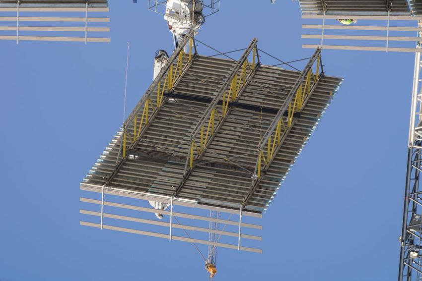
User Information DokaTruss table                                                                   System description

System description

DokaTruss table – The optimized                             Short construction times and substantial labor
tableform for building construction                         savings
at a record pace                                            Speed up your forming times
                                                            ▪ Maximum safety, speed and cost efficiency.
The DokaTruss table speeds up cycles in building con-       ▪ Tables sized up to 2,150 ft² (200 m²) are reposi-
struction.                                                    tioned safely and swiftly in a single crane cycle.
The tableforms, with large table tops exactly tailored to   ▪ Table lengths up to 100'-0'' (30.5 m) and widths up to
the layout, save crane cycles and enhance safety.             21'-0" (6.40 m) with only two truss sections.
The modular design offers many ways in which the            ▪ Labor savings – fewer work steps with legs spaced
floor-slab system can be adapted to different slab            up to 12'-0" (3.65 m) apart.
heights and thicknesses – you will only need material
that is actually used on the jobsite.

                                                            Superior adaptability

                                                            The perfect fit for your project
                                                             ▪ Lightweight, yet strong – optimally designed from a
                                                               combination of steel and aluminum.
                                                             ▪ The steel/aluminum combination offers low weight
                                                               while ensuring high capacities.
                                                             ▪ Modular and flexible – length and width can be con-
                                                               figured to meet any jobsite requirement.
                                                             ▪ Versatile – formwork for drop beams and for column
                                                               filler areas is integrated into the DokaTruss table.
                                                             ▪ Easily adaptable to fit any building layout and room
                                                               height using standard Doka parts.

                                                                                                           98109-203-09

               999810914 - 05/2021                                                                                        9
System description User Information DokaTruss table
System overview
Segment TT 12’-0" 2G Segment TT 24’-0" 2G Extension
A
L
F S T R
F
G E
F C
G
K
S
F
F T
G J
F M
B Q
G I
S
F
G E
F
G
D N
H
P P
O
98109-206-01
A C6 Alu Channel top TT 12’-0" K End protector C6 TT
B C6 Alu Channel bottom TT 12’-0" L Splice plate C6 TT
C C6 Alu Channel top TT 24’-0" M Splice plate C6/WS10 TT
D C6 Alu Channel bottom TT 24’-0" N Adjustment leg TT or Adjustment leg TT 2G
E Spacer C6 TT O Screw jack foot TT
F Standard TT 2G P Screw jack anti-dropout lock TT
G Strut TT 2G Q Fastening bolt TT
H Diagonal brace TT 6’-0" R Diagonal cross
I Multi-purpose waling WS10 Top50 S Diagonal cross adapter TT
J Handrail post T 1.80m T Lifting adapter TT + Shackle Xclimb 60 6.5t
10 999810914 - 05/2021User Information DokaTruss table System description
Truss section Fall protection
The Handrail post T 1.80m is bolted onto the multi-
Segment TT purpose waling of the extension, as a fall protection at
the slab edge.
Segment TT 12’-0" 2G or Segment TT 24’-0" 2G
Consisting of: Foot
C6 Alu Channels top TT (top chord) Room heights up to 13’-1 1/2" (4.00 m)
▪ Diagonal cross adapters TT with safety catches, for
fitting the horizontal diagonal crosses. Consisting of:
▪ Bolting with Standard TT and Strut TT:
- Hexagon bolt DIN 931 M20x90 Adjustment leg TT or Adjustment leg TT 2G
- Hexagon bolt DIN 934 M20
- Washer ISO 7089 20 Distinction:
Adjustment leg TT Adjustment leg TT 2G
98109-229-01
98109-229-02
Standard TT 2G
▪ Provided with holes for pinning the feet in place in
different height positions.
▪ Safety catches for fitting the vertical diagonal
X X
2G 2G Y
crosses.
▪ Lugs with holes for bolting Struts TT.
▪ Bolting with Strut TT: ▪ 25 % higher load-bearing
capacity
- Hexagon bolt DIN 931 M20x90 (see the section headed
- Hexagon nut DIN 934 M20 'Structural design')
- Washer ISO 7089 20 ▪ different baseplate (X)
▪ '2G' sticker (Y)
Strut TT 2G NOTICE
▪ Bolted to the lugs of the Strut TT at the bottom and When Adjustment leg TT and Adjustment leg
to the top chord at the top. TT 2G are both used, the lower load-bearing
capacity of the Adjustment leg TT applies!
Spacer C6 TT
▪ Is installed in the bottom chord between the C6 Alu Screw jack foot TT
channels. ▪ Screw jack anti-dropout lock TT for securing the
screw jack foot in the adjustment leg (2 locks per
adjustment leg).
C6 Alu Channels bottom TT (bottom chord)
▪ End protector C6 TT for protecting the channel posi-
tioned at the end of a truss section. The feet are pinned in place in the vertical legs (as stat-
ically required and according to the room height
▪ Bolting with Spacer C6 TT: needed) with Fastening bolts TT.
- Hexagon bolt DIN 931 M20x120
- Hexagon nut DIN 934 M20
▪ Foot adjusted to the required height (Pos. 1).
- Washer ISO 7089 20 ▪ Foot pinned in place. Fastening bolt secured with a
linch pin to prevent it dropping out (Pos. 2).
The segments are joined together using the Splice
plate C6 TT. 1 2
U
Extension Q
U
Q
Consisting of Multi-purpose waling WS10 Top50 and
Diagonal brace TT 6’-0". N
▪ The multi-purpose waling is joined to the 98109-209-11 98109-209-12
Segment TT using the Splice plate C6/WS10 TT.
N Adjustment leg TT or Adjustment leg TT 2G
Q Fastening bolt TT
U Linch pin
999810914 - 05/2021 11System description User Information DokaTruss table
Installation situations of the foot in the vertical leg: Diagonal crosses
during repositioning,
as propping
transporting and storage
Slide-in bracing crosses made of tubular steel, for
mounting between the truss sections.
Q N
Identified by:
▪ Embossed markings, e.g. 18.250
▪ Notched, color-coded clips (see the section headed
"System dimensions")
Q Basic rule:
O
98109-204-22
Vertical diagonal crosses are mounted to each verti-
N cal leg with a foot pinned to it.
P P
Crane hoisting points
98109-204-23
O
Consisting of Lifting adapter TT und Shackle Xclimb
60 6.5t
▪ are mounted to the top chord (Segment TT).
N Adjustment leg TT or Adjustment leg TT 2G
O Screw jack foot TT
P Screw jack anti-dropout lock TT Joists
Q Fastening bolt TT
Room heights over 13’-1 1/2 " (4.00 m) Follow the directions in the User Information
booklet of the beams being used!
Note:
For room heights over 13’-1 1/2" (4,00 m), instead of the Plywood
feet Doka Super Props are mounted on the segment by
means of Table heads Super Prop TT. Follow the directions in the User Information
Consult your Doka technician for details. booklet of the formwork sheets being used!
F
V
98109-204-26
W
F Standard TT 2G
V Table head Super Prop TT
W Doka Super Prop
12 999810914 - 05/2021User Information DokaTruss table System description
System dimensions
Truss section
Segment TT 12’-0" 2G Segment TT 24’-0" 2G Extension
a b c
h
i
d d d e e d
d1
f g g 98109-206-02
f1
a ... 11’-11 1/2" (364.5 cm)
b ... 23’-11 1/2" (730.0 cm)
c ... 3’-0" (100.0) to 8’-0" (245.0 cm)
d ... 5’-4" (162.5 cm)
d1 ... 6’-8" (203.0 cm)
e ... 6’-0" (183.0 cm)
f ... 10’-8" (325.0 cm)
f1 ... 12’-0" (365.5 cm)
g ... 11’-4" (345.5 cm)
h ... 5’-4 1/2" (164.5 cm)
i ... 6’-8 1/2" (205.0 cm) to 12’-4 1/2" (377.0 cm)*
*) see the section headed "Height adjustment".
Distance between truss sections
Diagonal cross (B) Center-to-center distance j
Marked with between truss sections (A)
Designation
color-coded clip notches [inch] [cm]
Diagonal cross 9.150 red — 4’-3" 129.5
Diagonal cross 9.175 light green — 5’-2 1/8" 157.8
Diagonal cross 9.200 blue — 6’-1" 185.2
Diagonal cross 9.250 yellow — 7’-9 3/4" 238.3
B Diagonal cross 9.300 orange — 9’-6 1/4" 290.3
Diagonal cross 12.100 green 1 3’-3 1/4" 100.0
Diagonal cross 12.150 red 1 4’-11" 150.0
A A Diagonal cross 12.175 light green 1 5’-9" 175.0
Diagonal cross 12.200 blue 1 6’-6 3/4" 200.0
B
Diagonal cross 12.250 yellow 1 8’-2 3/8" 250.0
Diagonal cross 12.300 orange 1 9’-10 1/8" 300.0
j
98109-206-05
Diagonal cross 18.100 green 3 5’-5 3/8" 166.0
Diagonal cross 18.150 red 3 6’-6 3/4" 200.2
Diagonal cross 18.175 light green 3 7’-2 1/2" 219.5
Diagonal cross 18.200 blue 3 7’-10 1/2" 240.0
Diagonal cross 18.250 yellow 3 9’-3 3/8" 283.0
Diagonal cross 18.300 orange 3 10’-9 1/8" 328.0
Diagonal cross TT 12’-0" light blue 3 12’-0" 365.8
999810914 - 05/2021 13System description User Information DokaTruss table
Table weight
Weight of table with 2 truss sections, as a function of the spacing between the joists (guide values)
Spacing of joists
Width of table
Length of table (l) 24" (60 cm) 19 3/16" (50 cm) 16" (40 cm) 12" (30 cm)
(joists)
[lb] [kg] [lb] [kg] [lb] [kg] [lb] [kg]
Doka beam H20 2.45m 832 377.3 859 389.5 915 414.9 997 452.1
Segment TT 12’-0" 2G Doka beam H20 3.60m 928 420.8 968 438.9 1048 475.2 1169 530.1
l = 12’-0" (3.65 m) Doka beam H20 4.90m 1044 473.4 1098 497.9 1207 547.4 1370 621.7
Doka beam H20 5.90m 1139 516.5 1205 546.4 1336 605.9 1532 694.8
Doka beam H20 2.45m 1435 651.1 1518 688.8 1601 726.5 1766 801.3
Segment TT 24’-0" 2G Doka beam H20 3.60m 1612 731.4 1732 785.9 1853 840.8 2094 950.1
l = 24’-0" (7.30 m) Doka beam H20 4.90m 1825 828.0 1988 902.0 2151 975.9 2478 1124.2
Doka beam H20 5.90m 1998 906.5 2195 995.9 2391 1084.8 2784 1263.1
Doka beam H20 2.45m 415 188.2 443 200.9 470 213.1 525 238.1
Extension 8’-0" Doka beam H20 3.60m 465 210.9 506 229.5 546 247.6 626 283.9
l = 8’-0" (2.45 m) Doka beam H20 4.90m 523 237.2 577 261.7 632 286.6 741 336.1
Doka beam H20 5.90m 567 257.1 632 286.6 698 316.6 829 376.0
The weights stated in this table include the weights of
the following components:
▪ 2 truss sections
(Segments TT / extension)
▪ Joists
(Doka beams H20 incl. connectors)
▪ Diagonal crosses
Note:
For determining a table's actual total weight, the
weight of the splice plates, feet, mounted parts, and the
plywood used must be taken into account.
▪ Splice plates C6 TT (incl. screw set) to join 2 truss
sections with 2 further truss sections (= 8 pcs.):
182.8 lbs (82.9 kg)
▪ Foot (adjustment leg, screw jack foot, fastening
bolt)
- With Screw jack foot TT 3’-2": 48.2 lbs (21.9 kg)
- With Screw jack foot TT 4’-2": 52.6 lbs (23.9 kg)
▪ Plywood 3/4" (19 mm):
2.5 psf (12.2 kg/m2)
14 999810914 - 05/2021User Information DokaTruss table System description
Table sizes
Table with 2 truss sections
Plan view:
A
b
A
98109-200-27
a
a ... Length of table
b ... Width of table
A Truss section
▪ Length of table:
- 18’-0" (5.50 m) to 100’-0" (30.50 m)
▪ Width of table:
- 5’-11" (1.80 m) to 21'-0" (6.40 m)
Table with 3 truss sections
Plan view:
B B
A
A
b
A
98109-200-28
a
a ... Length of table
b ... Width of table
A Truss section
B Spreader beam
▪ Length of table:
- 18’-0" (5.50 m) to 49’-2 1/2" (15.00 m)
▪ Width of table:
- 19’-8" (6.00 m) to 34’-5" (10.50 m)
999810914 - 05/2021 15System description User Information DokaTruss table
Possible combinations
Y X
C C
28’-0" (8.50 m) A
98109-203-01
Y X
C C
40’-0" (12.20 m) B
98109-203-02
Y X
C C
52’-0" (15.85 m) A B
98109-203-03
Y X
C C
64’-0" (19.50 m) B B
98109-203-04
Y X
C C
76’-0" (23.15 m) A B B
98109-203-05
Y X
C C
88’-0" (26.80 m) B B B
98109-203-06
Y X
C C
A B B B
100’-0" (30.50 m)
98109-203-07
l
l ... max. 100’-0" (30.50 m)
The positions of the crane hoisting points shown here may vary in practice. Attention must be paid to the relevant assembly plan / shop drawing!
A Segment TT 12’-0" 2G
B Segment TT 24’-0" 2G
C Extension 8’-0"
X Front crane hoisting point
Y Rear crane hoisting point
16 999810914 - 05/2021User Information DokaTruss table System description
Number of components per truss section
Length of table
Segment TT 12’-0" 2G (A) Segment TT 24’-0" 2G (B) Extension 8’-0" (C)
28’-0" (8.50 m) 1 — 2
40’-0" (12.20 m) — 1 2
52’-0" (15.85 m) 1 1 2
64’-0" (19.50 m) — 2 2
76’-0" (23.15 m) 1 2 2
88’-0" (26.80 m) — 3 2
100’-0" (30.50 m) 1 3 2
Note:
In addition to the combinations shown here, it is also
possible to adapt the length of table to meet project-
specific requirements (e.g. by using extensions of dif-
ferent lengths).
999810914 - 05/2021 17System description User Information DokaTruss table
Instructions for assembly and use
Depending on the project, the actual design and
sequence of operations may differ from the descrip- NOTICE
tions given in this booklet. ➤ Use personal fall-arrest systems to protect
▪ Follow the shop drawing / assembly plan or ask your against falls (e.g. safety harness).
Doka technician. ➤ Tilt up the hinge panels by crane and place floor
props beneath them (see the section headed 'Hinge
CAUTION panel').
➤ DokaTruss tables may only be used to form
horizontal slabs.
➤ It is forbidden to use them in inclined situa-
tions.
➤ Never place tables on top of one another.
CAUTION
Risk of small-sized tables tipping over!
➤ If necessary, secure them with a back-stay!
Note:
All necessary traffic routes must be prepared at the site!
Erecting the formwork
98109-207-04
➤ Move the table to its usage location by crane, raise it
to the intended operational height, extend the feet,
➤ Put up all the other tables and secure them if neces-
and adjust the table's height (see the section headed
sary.
"Height adjustment").
If necessary, secure the table to the building.
98109-207-05
98109-207-03
18 999810914 - 05/2021User Information DokaTruss table System description
➤ Mount additional fall protection (see the section Pouring
headed "Fall protection on the formwork").
To protect the surface of the form-facing, we recom-
mend using a vibrator with a protective rubber cap.
Stripping and repositioning the
formwork
NOTICE
It is essential to follow the instructions given
here and the instructions in the section headed
'Reshoring props, concrete technology and
stripping'.
➤ Check the concrete strength.
➤ Take the load off the tables and lower them approx.
98109-207-02
4" (10 cm) with the screw jack foot.
➤ If necessary, put up props in the filler zones or insert
insertion beams (see the section headed "Fillers with
plywood strips").
➤ Insert plywood strips between the tables, and nail
where needed (see the section headed "Fillers with
plywood strips").
98109-200-25
➤ Remove the fillers.
98109-207-01
The T ledge makes it easier to strip the form- 98109-214-10
work.
It is only needed in the area where stripping
begins.
9767-299-01
a
a ... max. 1/2" (15 mm)
➤ Form the slab bulkheads (see the section headed
"Slab bulkheads").
➤ Spray the form-facing with release agent.
➤ Place the reinforcement.
999810914 - 05/2021 19System description User Information DokaTruss table
Tilting down the hinge panel
NOTICE
➤ Use personal fall-arrest systems to protect
against falls (e.g. safety harness).
1) Attach the lifting chain/cable to the lifting bracket of
the hinge panel and remove the floor prop.
2) Tilt down the hinge panel with the assistance of a
crane and dismount the plumbing strut.
1 2
A
C B A
98109-207-13
A Hinge panel
B Floor prop Eurex top
C Plumbing strut
➤ Lift the table to its next usage location (see the sec-
tion headed 'Repositioning'.)
Reshoring
NOTICE
It is essential to follow the instructions given
here and the instructions in the section headed
'Reshoring props, concrete technology and
stripping'.
➤ Before pouring the next floor-slab (i.e. above the one
that has just been stripped), install reshoring props.
20 999810914 - 05/2021User Information DokaTruss table System description
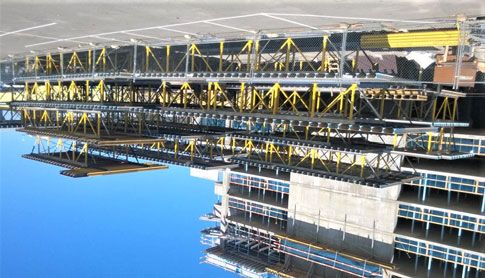
Adaptation to building layout
The tableforms can be adapted to the building layout in Fillers with plywood strips
the following ways:
▪ Table sizes and shapes adapted to the project
▪ Filler zones with plywood strips NOTICE
▪ Fillers using hinge panels The width 'c' of the plywood strip, the permitted
slab thickness, and the required type of prop-
ping must be statically determined on a proj-
B B ect-specific basis!
Support on the DokaTruss table
c
a a
C
C A D A A
98109-214-01
b
a ... Support on the beam min. 2" (5 cm)
b ... Distance between two tables min. 6" (15 cm)
98109-217-01
(Stripping allowance)
c ... Width of plywood strip
A Filler zone with plywood strip
B Adaptation in the longitudinal direction with no additional propping
C Hinge panel
D Table with 3 truss sections c
98109-214-02
center-propped
c
98109-214-08
999810914 - 05/2021 21System description User Information DokaTruss table
double-propped Location of the Insertion beams
➤ Place the insertion beams (A) at the ends of the
c
tables, as close as possible to the edge.
➤ Do not space the insertion beams any further apart
than the beams of the table.
➤ Insert an extra insertion beam (B) under the joint
between the formwork sheets (C) .
98109-214-09
with insertion beam
with no additional propping
c
C
A
98109-214-03
center-propped B
98109-223-01
c
NOTICE
The joint where the sheets abut (D) must
always be positioned over the raised support
surface of the insertion beam (A) .
D
98109-214-04
c ... Width of plywood strip
For very thick slabs, the insertion beam can be A
fitted with its raised support surface facing 98109-214-03
downwards, and wedged up to the right height If this is not possible, the insertion beam can be fitted with
on the table waling. This permits bigger filler its raised support surface facing downwards, and wedged
widths. up to the correct height on the Segment TT.
Please consult your Doka technician.
Example: Incorporating columns into the filler
zone:
22 999810914 - 05/2021User Information DokaTruss table System description
at wall or column junctions Propping the filler zones
This additional propping is set up using Beams H20,
Supporting heads H20 DF and Floor props Eurex top.
C
A
B
A 9768-215-01
A Supporting head H20 DF
b B Doka beam H20
98109-214-05
C Hole in the supporting head
b ... min. 6" (15 cm) (for fixing to the beam)
A Squared timber approx. 2x4 (5 x 8 cm) (W x H)
(fastened to the wall) ➤ Place the Supporting head H20 DF on the inside
tube of the floor prop and secure it with the integral
Wall junctions on both sides spring-steel stirrup.
A filler is only needed on one side facing the wall. 1 2 3
9767-233-01
A A
98109-214-14 b 98109-214-15
b ... min. 1’-0" (30 cm)
A Squared timber approx. 2x4 (5 x 8 cm) (W x H)
Combining tables in the longitudinal
(fastened to the wall) and transverse directions
a
b
98109-214-07
a ... min. 2" (5 cm)
b ... min. 6" (15 cm)
999810914 - 05/2021 23System description User Information DokaTruss table
Adaptation in the longitudinal Note:
Separate statical verification must be performed for
direction extensions within the structure.
Tables can be adapted to the building layout in the lon- ▪ Version 1: Propping with a floor prop
gitudinal direction by extending the truss sections with
c
the Multi-purpose walings WS10 Top50 3’-0" (100 cm)
to 8’-0" (245 cm).
Note:
For extensions longer than 8’-0" (245 cm), ask your
Doka technician! F
A D
Nuts & bolts, etc. needed for each extension:
▪ 5 hexagon bolts M20x100
▪ 5 hexagon nuts M20 B
▪ 5 washers 20
Extensions at the slab edge E C
The table is extended outwards, resulting in an area 'b'
free to work on beyond the slab bulkhead (no full-face
concrete load).
98109-214-13
c ... 5’-0" (150 cm) to 8’-0" (245 cm)
A Multi-purpose waling WS10 Top50
a B Diagonal brace TT 6’-0"
C Segment TT
b D Splice plate C6/WS10 TT
E Floor prop Eurex top
F Dokamatic strut connection
▪ Version 2: Spindle strut T7 instead of the diago-
nal brace
A D
c
B
C
A D
G
98109-214-12
a ... 3’-0" (100 cm) to 8’-0" (245 cm)
b ... 3’-0" (100 cm)
C
A Multi-purpose waling WS10 Top50
B Diagonal brace TT 6’-0"
C Segment TT
D Splice plate C6/WS10 TT
98109-214-11
Extensions within the structure c ... 5’-0" (150 cm) to 8’-0" (245 cm)
A Multi-purpose waling WS10 Top50
Extensions within the structure of up to 5'-0" (150 cm) C Segment TT
(see the section headed 'Extensions at the slab edge'). D Splice plate C6/WS10 TT
Extensions within the structure of more than 5'-0" G Spindle strut T7
(150 cm) must be additionally supported.
24 999810914 - 05/2021User Information DokaTruss table System description
Hinge panel Assembly
b
L
K G E
F
c
C
J G D
I A B
d
a
H
c
98109-207-06
98109-207-12
a ... max. 11’-9 3/4" (3.60 m)
b ... max. 5’-0" (1.50 m)
c ... min. 4" (10 cm)
d ... adapted to the spacing between the joists of the table
K Hinge panel
L DokaTruss table A Stringer
B Joist
The hinge panel is mounted to the side of the Doka- C Brace stirrup 8 + Safety plate for brace stirrup 8
Truss table. D Tilting connector TT
▪ It is used for adaptation between columns or in wall E Strut shoe EB (for connecting the plumbing strut)
niches (Pos. 1). F Lifting bracket
▪ For stripping and repositioning the tableform, the G Shim 1 1/8" x 4 1/2" (29 x 120 mm) (W x H)
panel is tilted down (Pos. 2). H Squared timber approx. 2x2 (5 x 5 cm) (W x H)
I Plywood
Function of the hinge panel (simplified drawing): J Supporting head H20 DF (for connecting the floor prop)
Tableform closed: While being repositioned:
1 2 Tools needed:
▪ Reversible ratchet 1/2"
K
▪ Box nut 24
R L ▪ Fork wrench 24
K
Pre-assembling the hinge panel:
➤ Join the stringers and joists (e.g. with wood screws
R and Brace stirrup 8).
➤ Bolt the Tilting connector TT and the shims to the
joist.
Holes to be drilled: diam. 3/4" (18 mm).
98109-227-01
K Hinge panel
L DokaTruss table
R Prop
G
D
98109-220-01
D Tilting connector TT
G Shim 1 1/8" x 4 1/2" (29 x 120 mm) (W x H)
999810914 - 05/2021 25System description User Information DokaTruss table
➤ Bolt the lifting bracket to the same joist as the tilting Mounting to the table:
connector. ➤ Fasten a shim to either side of the joist of the table,
Holes to be drilled: diam. 3/4" (18 mm). and drill a hole.
Hole to be drilled: diam. 1 1/4" (31 mm).
e f
K L
F
98109-220-03
M G
F Lifting bracket
g
98109-207-17
➤ Bolt the Strut shoe EB and the shims to the outside
stringer. e ... min. 1" (2.5 cm)
Hole to be drilled: diam. 3/4" (18 mm). f ... max. 8 1/8" (20.5 cm)
g ... min. 2’-0" (60.0 cm)
G Shim 1 1/8" x 4 1/2" (29 x 120 mm) (W x H)
K Hinge panel
G L DokaTruss table
M Drilled hole diam. 1 1/4" (31 mm)
➤ Lift the pre-assembled hinge panel to the table with
E
98109-220-02 the lifting strap and crane.
E Strut shoe EB ➤ Pin it to the table with the hinge bolt D30 TT and
G Shim 1 1/8" x 4 1/2" (29 x 120 mm) (W x H) secure it with a linch pin.
Nuts & bolts, etc. needed for each Strut shoe EB:
▪ 1 hexagon bolt M16x120
▪ 1 hexagon nut M16 K
▪ 1 washer M16 (ISO 7094)
➤ Mount a squared timber to the underside of the
joists, using two wood screws for each joist, to
strengthen the stringers. N
H
98109-220-04
98109-207-16
H Squared timber approx. 2x2 (5 x 5 cm) (W x H)
K Hinge panel
N Hinge bolt D30 TT + linch pin
➤ Lay the formwork sheets and screw them on.
26 999810914 - 05/2021User Information DokaTruss table System description
Use at the slab edge Tableform closed:
The sequence shown here is based on a hinge panel at
the slab edge. For hinge panels within the structure,
Floor props Eurex top are used instead of the plumbing
struts.
NOTICE
➤ Use personal fall-arrest systems to protect
against falls (e.g. safety harness).
➤ Pin the plumbing strut into the Strut shoe EB, which
is mounted to the hinge panel.
➤ Tilt up the hinge panel by crane.
E 98109-207-14
Table while being repositioned:
O
g
98109-207-10
E Strut shoe EB
O Plumbing strut
h
➤ Fix the plumbing strut to the ground with a Doka
express anchor.
Follow the directions in the 'Doka express
anchor 16x125mm' Fitting Instructions!
i
98109-207-18
➤ Put up the floor prop with supporting head. g ... min. 2'-0" (60.0 cm)
h ... max. 5'-8" (1.73 m)
i ... approx. 1'-6" (45.0 cm)
O P
Q
98109-207-15
O Plumbing strut
P Floor prop Eurex top
Q Doka express anchor 16x125mm
999810914 - 05/2021 27System description User Information DokaTruss table
Table with 3 truss sections
A table with 3 truss sections and a width of up to 34’-5"
(10.50 m) can be repositioned in a single crane cycle.
To do this, spreader beams with crane hoisting points
are mounted at right angles to the truss sections.
1
E
1 D
C
1
a
2
B
1
B
2 98109-226-03
1
2
1
B
2
2
A
A F G
A
B
A
b 98109-226-02
98109-226-01
Drawing not showing the superstructure
a ... 2’-1 1/2" (650 mm)
b ... max. 10" (255 mm)
A Truss section
B Spreader beam (e.g. two C8 profiles or U200 S235 profiles; see
shop drawing / assembly plan)
C Tie rod 15.0mm
a
D Super plate 15.0
E Hexagon nut 15.0 (width-across 30 mm)
F Lifting adapter TT
G Shackle Xclimb 60 6.5t
B
Each shackle is supplied with:
▪ 1 threaded bolt M24x115 b b
▪ 1 hexagon nut M24
▪ 1 cotter pin
98109-226-04
Follow the directions in the "Shackle Xclimb 60
a ... max. 34’-5" (10.50 m)
6.5t" Operating Instructions! b ... 3’ 3 1/8" (1.00 m) to 12’-0" (3.60 m)
B Spreader beam (e.g. two C8 profiles or U200 S235 profiles; see
Nuts & bolts, etc. needed for each lifting adapter: shop drawing / assembly plan)
▪ 1 hexagon bolt M20x100
▪ 1 hexagon nut M20 Note:
▪ 1 washer 20 Separate statical verification must be performed for
tables with 3 truss sections weighing more than
15430 lbs (7000 kg).
28 999810914 - 05/2021User Information DokaTruss table System description
Height adjustment
Room heights up to 13’-1 1/2" (4.00 m) NOTICE
Reduction in the permitted leg loads must be
▪ Rough adjustment in 6" (15 cm) increments is car- taken into account, depending on the room
ried out by pinning the feet to the segment in one of height (see the section headed "Structural
5 possible positions. design")!
▪ Fine adjustment is made with the screw jack feet.
Room heights over 13’-1 1/2 " (4.00 m)
Positions for fixing the feet to the Segment TT
Note:
For room heights over 13’-1 1/2" (4,00 m), instead of the
feet Doka Super Props are mounted on the segment by
means of Table heads Super Prop TT.
Consult your Doka technician for details.
D 5
4
h min
C 3
2
h max
1
A
98109-209-05
B
98109-209-04
98109-209-03
98109-209-02
98109-209-01
A Adjustment leg TT or Adjustment leg TT 2G
B Screw jack foot TT
C Segment TT
D Fastening bolt TT
With Screw jack foot TT 3’-2"
Room height (h) Fixing
h min* h max position
7’-5" (227 cm) 10’-1 1/2" (310 cm) Pos. 5
7’-11" (242 cm) 10’-7 1/2" (325 cm) Pos. 4
8’-5" (257 cm) 11’-1 1/2" (340 cm) Pos. 3
8’-11" (272 cm) 11’-7 1/2" (355 cm) Pos. 2
9’-5" (287 cm) 12’-1 1/2" (370 cm) Pos. 1
With Screw jack foot TT 4’-2"
Room height (h) Fixing
h min* h max position
7’-11" (242 cm) 11’-1 1/2" (340 cm) Pos. 5
8’-5" (257 cm) 11’-7 1/2" (355 cm) Pos. 4
8’-11" (272 cm) 12’-1 1/2" (370 cm) Pos. 3
9’-5" (287 cm) 12’-7 1/2" (385 cm) Pos. 2
9’-11" (302 cm) 13’-1 1/2" (400 cm) Pos. 1
*) Stripping allowance: 0’-2" (5 cm) (already allowed for in the table)
Table superstructure: Doka beam H20 and plywood 3/4" (19 mm)
(already allowed for in the table)
999810914 - 05/2021 29System description User Information DokaTruss table
Drop beams
at the slab edge I Handrail post T 1.80m
(optionally with Toeboard holder T 1.80m)
J Connecting pin 10cm
with Drop beam connector TT and Drop beam wal- K Spring cotter 5mm
ing TT
Note:
Drop beams with a width 'b' greater than 1'-0" (30 cm)
require additional propping with Floor props Eurex top.
b
98109-216-01
▪ For drop beam heights between 8" (20 cm) and
2’-5 1/2" (75 cm), in 2" (5 cm) increments.
For heights of drop beams outside the 2" (5 cm) grid: M F
see project plan.
▪ For bulkhead heights of up to 2’-11 1/2" (90 cm).
Note: L
For drop beams, separate statical verification must be
performed.
98109-208-02
b ... dependent on the length of the multi-purpose waling and on the
load-bearing capacity of the floor prop
I F Multi-purpose waling WS10 Top50
b E F
L Floor prop Eurex top
M Dokamatic strut connection
D
Note:
G
C For forming larger sized drop beams, ask your Doka
d
technician!
e
A
in mid-slab
B H
F J K
Note:
For forming drop beams in mid-slab, ask your Doka
G technician!
98109-208-01
b ... max. 1'-0" (30 cm)
d ... max. 2'-11 1/2" (90 cm)
e ... 8" (20 cm) to 2'-5 1/2" (75 cm)
A Drop beam waling TT
B Drop beam connector TT
C Formwork sheet
D Wooden spacer (size as needed)
E Frami panel (size as needed)
F Multi-purpose waling WS10 Top50
G Spindle strut T7 75/110cm
H Formwork element connector FF20/50
30 999810914 - 05/2021User Information DokaTruss table System description
Slab bulkheads
with Framax universal corner waling with Universal end-shutter support
30cm
a
98109-211-01
98109-210-01
c
A Max. influence width a
D for slabs of thickness
E Config- 8" 10" 1’-0"
Fastened with
uration (20 cm) (25 cm) (30 cm)
B 2’ 11 1/2" 1’-8" 1’-0"
A 4 nails 10d (3.1x80)
(90 cm) (50 cm) (30 cm)
d
4 Spax screws
7’-2 1/2" 6’-3" 5’-3"
B 3/
16" x 1 /4" (4x40)
3
(220 cm) (190 cm) (160 cm)
(fully threaded)
C
Fastened with nails (configuration A)
98109-211-02
c ... 2 1/3" (6 cm) to 6 1/3" (16 cm)
d ... Slab thickness max. 1’-4" (40 cm)
A Frami panel
B Framax universal corner waling
C Dokamatic edge clamp
C
D Super plate 15.0
B A
E Frami universal fixing bolt 5-12cm
d
Use a 3/4" (20 mm) diameter bit to drill the B
holes through the plywood.
Unneeded holes in the plywood should be
closed off on the site with Universal plugs
R20/25. 98109-210-02
d ... Slab thickness max. 1’-0" (30 cm)
A Universal end-shutter support 30cm
B Nail 10d (3.1x80)
C Formwork sheet
999810914 - 05/2021 31System description User Information DokaTruss table
Stripping tip:
➤ Take out the nails on the bulkhead side
➤ Put the claw of a hammer under the corner
(put a piece of wood under it to protect the
plywood sheeting)
➤ Lever up the end-shutter support
Tr652-203-02
Fastened with Spax screws (configuration B)
C
E
D A
d
D
98109-210-03
d ... Slab thickness max. 1’-0" (30 cm)
A Universal end-shutter support 30cm
C Formwork sheet
D Spax screw 3/16" x 1 3/4" (4x40)
E Doka beam H20
32 999810914 - 05/2021User Information DokaTruss table System description
Fall protection on the formwork
Edge protection system XP
CAUTION
➤ Use the Edge protection system XP only in
combination with the Handrail post XP
1.20m.
NOTICE A
▪ Ideally, fall protection should be mounted B
from below.
▪ When installing/removing edge protection
from above, the crew must use a personal
fall-arrest system to protect against falls
(e.g. safety harness).
▪ Suitable anchorage points must be defined
by a skilled person appointed by the con-
tractor.
C
Follow the directions in the 'Edge protection
system XP' User Information booklet. D
Handrail clamp S
98109-222-02
A Protective grating or guardrail planks
B Handrail post XP 1.20m
A
C Railing clamp XP 40cm
D Joist
Assembly:
➤ Wedge the Railing clamps XP firmly to the joists
(clamping range 3/4" (2 cm) to 1’-5" (43 cm)).
B
➤ Push the Handrail posts XP 1.20m into the post-
holding fixtures on the railing clamps until the locking
mechanism engages.
➤ Fit on a Protective grating XP or guardrail planks.
D ➤ Fix the Protective grating XP or the guardrail planks
to the Handrail post XP.
Follow the directions in the User Information
booklet "Edge protection system XP"!
98109-222-01
A Guardrail plank
B Handrail clamp S
D Joist
Assembly:
➤ Wedge the handrail clamps firmly to the joists
(clamping range 3/4" (2 cm) to 1’-5" (43 cm)).
➤ Secure the guardrail planks to the handrail post
plates.
Follow the directions in the User Information
booklet "Handrail clamp S"!
999810914 - 05/2021 33Structural design User Information DokaTruss table
Structural design
Follow the directions in the Calculation Guide
'DokaTruss table' or ask your Doka technician.
Segment TT 24’-0" 2G q1 q1
with 3 feet and 5 q2
Standards TT
98109-213-04
98109-213-02
f d1 d
e
a a
V
Segment TT 24’-0" 2G q3
with 5 feet and 5 Standards TT
▪ Separate statical verification must be performed!
98109-213-01
d
b c c b
V
a ... 11’-4" (345.5 cm)
b ... 5’-0" (162.5 cm) NOTICE
c ... 6’-0" (183.0 cm) Reduction in the permitted leg loads must be
d ... 2’-10 1/2" (87.4 cm)
d1 ... 3’-7 1/2" (110.8 cm)
taken into account, depending on the room
e ... 8’-0" (245.0 cm) height!
f ... 4’-4" (132.0 cm)
Permitted load
▪ Concrete load
▪ Live load
▪ Dead weight of the table incl. superstructure
q1 = 2 kips/ft (29 kN/m)
q2 = 0.3 kips/ft (5 kN/m)
q3 = 3.15 kips/ft (46 kN/m)
Max. point load on the bottom chord
(during repositioning)
F1 = 10 kips (45 kN)
F2 = 2.25 kips (10 kN)
See the section headed "Additional measures for
large tables".
Max. leg load
V = 22,5 kips (100 kN)
for room heights of up to 9’-5" (2.87 m) (Adjustment
leg TT) or 10’-1 1/2" (3.10 m) (Adjustment leg TT 2G)
34 999810914 - 05/2021User Information DokaTruss table Structural design
Permitted leg loads, depending on
the room height
The permitted leg loads depend on the following fac-
tors:
▪ screw-jack foot used
(Screw-jack foot TT 3' 2" or Screw-jack foot TT 4' 2")
▪ adjustment leg used
(Adjustment leg TT or Adjustment leg TT 2G)
▪ Positions for fixing the feet to the Segment (1 - 5)
(See the section headed "Height adjustment")
h
B
98109-204-24
A
V V V
h ... Room height
A Screw jack foot TT 3’-2" or Screw jack foot TT 4’-2"
B Adjustment leg TT or Adjustment leg TT 2G
Fixing positions
98109-209-15
98109-209-14
98109-209-13
98109-209-16
98109-209-17
5
4
3
2
1
NOTICE
The leg loads stated here apply only for top-
held tables. No horizontal loads are trans-
ferred!
Note:
For room heights over 13’-1 1/2" (4,00 m), instead of the
feet Doka Super Props are mounted on the segment by
means of Table heads Super Prop TT.
Consult your Doka technician for details.
999810914 - 05/2021 35Structural design User Information DokaTruss table
Screw jack foot TT 3'-2" (imperial)
Permitted leg load [kip] Adjustment leg TT Permitted leg load [kip] Adjustment leg TT 2G
Room Fixing position Room Fixing position
height h [ft] Pos. 5 Pos. 4 Pos. 3 Pos. 2 Pos. 1 height h [ft] Pos. 5 Pos. 4 Pos. 3 Pos. 2 Pos. 1
7’-5" 22.5 — — — — 7’-5" 22.5 — — — —
7’-11" 22.1 22.5 — — — 7’-11" 22.5 22.5 — — —
8’-5" 20.7 21.6 22.5 — — 8’-5" 22.5 22.5 22.5 — —
8’-11" 20.1 19.9 20.9 22.5 — 8’-11" 22.5 22.5 22.5 22.5 —
9’-5" 19.0 18.7 19.0 20.2 21.9 9’-5" 22.5 22.5 22.5 22.5 22.5
10’-1 1/2" 16.0 16.8 17.2 17.8 18.9 10’-1 1/2" 22.2 22.5 22.5 22.5 22.5
10’-7 1/2" — 14.4 15.6 16.3 17.1 10’-7 1/2" — 19.6 21.1 21.2 21.2
11’-1 1/2" — — 13.1 14.7 15.6 11’-1 1/2" — — 17.6 19.1 19.4
11’-7 1/2" — — — 12.2 13.9 11’-7 1/2" — — — 16.1 17.6
12’-1 1/2" — — — — 11.4 12’-1 1/2" — — — — 14.6
22 22 5
Permitted leg load [kip]
Permitted leg load [kip]
4
20 20
3
18 18
2
5
16 16 1
4
3
14 2 14
98109-100-01 1 98109-100-04
8.0 9.0 10.0 11.0 12.0 8.0 9.0 10.0 11.0 12.0
Room height h [ft] Room height h [ft]
Screw jack foot TT 4'-2" (imperial)
Permitted leg load [kip] Adjustment leg TT Permitted leg load [kip] Adjustment leg TT 2G
Room Fixing position Room Fixing position
height h [ft] Pos. 5 Pos. 4 Pos. 3 Pos. 2 Pos. 1 height h [ft] Pos. 5 Pos. 4 Pos. 3 Pos. 2 Pos. 1
10’-7 1/2" 16.3 10’-7 1/2" 21.5
Screw jack foot TT 3’-2" Screw jack foot TT 3’-2"
11’-1 1/2" 14.1 14.8 11’-1 1/2" 18.7 19.5
11’-7 1/2" — 12.6 13.5 11’-7 1/2" — 16.5 17.5
12’-1 1/2" — — 11.4 12.5 12’-1 1/2" — — 14.7 15.9
12’-7 1/2" — — — 10.4 11.7 12’-7 1/2" — — — 13.3 14.6
13’-1 1/2" — — — — 9.6 13’-1 1/2" — — — — 12.1
22 22
20 20 5
Permitted leg load [kip]
Permitted leg load [kip]
18 18 4
16 16 3
5
2
14 4
14
1
3
12 12
2
1
98109-101-01 98109-101-04
10 10
10.0 11.0 12.0 13.0 10.0 11.0 12.0 13.0
Room height h [ft] Room height h [ft]
36 999810914 - 05/2021User Information DokaTruss table Structural design
Screw jack foot TT 3'-2" (metric)
Permitted leg load [kN] Adjustment leg TT Permitted leg load [kN] Adjustment leg TT 2G
Room Fixing position Room Fixing position
height h [m] Pos. 5 Pos. 4 Pos. 3 Pos. 2 Pos. 1 height h [m] Pos. 5 Pos. 4 Pos. 3 Pos. 2 Pos. 1
2.27 100.0 — — — — 2.27 100.0 — — — —
2.42 98.3 100.0 — — — 2.42 100.0 100.0 — — —
2.57 92.1 96.1 100.0 — — 2.57 100.0 100.0 100.0 — —
2.72 89.4 88.5 93.0 100.0 — 2.72 100.0 100.0 100.0 100.0 —
2.87 84.5 83.2 84.5 89.9 97.4 2.87 100.0 100.0 100.0 100.0 100.0
3.10 71.2 74.7 76.5 79.2 84.1 3.10 98.8 100.0 100.0 100.0 100.0
3.25 — 64.1 69.4 72.5 76.1 3.25 — 87.2 93.9 94.3 94.3
3.40 — — 58.3 65.4 69.4 3.40 — — 78.3 85.0 86.3
3.55 — — — 54.3 61.8 3.55 — — — 71.6 77.4
3.70 — — — — 50.7 3.70 — — — — 64.9
100 100
5
Permitted leg load [kN]
Permitted leg load [kN]
90 90 4
3
80 80
2
5
70 70 1
4
3
2
60 98109-100-02
1 60 98109-100-03
2.30 2.50 2.70 2.90 3.10 3.30 3.50 3.70 2.30 2.50 2.70 2.90 3.10 3.30 3.50 3.70
Room height h [m] Room height h [m]
Screw jack foot TT 4'-2" (metric)
Permitted leg load [kN] Adjustment leg TT Permitted leg load [kN] Adjustment leg TT 2G
Room Fixing position Room Fixing position
height h [m] Pos. 5 Pos. 4 Pos. 3 Pos. 2 Pos. 1 height h [m] Pos. 5 Pos. 4 Pos. 3 Pos. 2 Pos. 1
3.25 72.5 3.25 95.6
Screw jack foot TT 3’-2" Screw jack foot TT 3’-2"
3.40 62.7 65.8 3.40 83.2 86.7
3.55 — 56.0 60.1 3.55 — 73.4 77.8
3.70 — — 50.7 55.6 3.70 — — 65.4 70.7
3.85 — — — 46.3 52.0 3.85 — — — 59.2 64.9
4.00 — — — — 42.7 4.00 — — — — 53.8
100 100
90 90 5
Permitted leg load [kN]
Permitted leg load [kN]
80 80 4
3
70 70
5
2
60 4 60 1
3
50 2 50
1
98109-101-02 98109-101-03
3.10 3.30 3.50 3.70 3.90 4.10 3.10 3.30 3.50 3.70 3.90 4.10
Room height h [m] Room height h [m]
999810914 - 05/2021 37Repositioning User Information DokaTruss table
Repositioning
General instructions on repositioning
NOTICE
WARNING
Observe the following points for horizontal
➤ The conveyance of persons is forbidden!
traveling:
➤ Before repositioning the tableform, remove
any loose items (e.g. fitting planks) from it. ▪ Take particular care with:
- height offsets
NOTICE - steps
▪ It is only permitted to travel tables that have - floor holes
been assembled and braced in accordance ▪ Bridge any openings in the floor with suffi-
with the assembly plans and erection rules ciently strong planking secured so that it
given in the User Information booklet. cannot slip away to either side, or close off
▪ Exposed fall-hazard locations open up at openings with sufficiently strong side rail-
the slab edge while repositioning the table. ings!
The whole area around the table to be repo-
sitioned must be closed off by attaching an NOTICE
access prohibition barrier. Observe the following points for vertical
▪ Use personal fall-arrest systems to protect repositioning by crane:
against falls (e.g. safety harness). ▪ It is important to ensure that the crane has
sufficient lifting capacity.
▪ It is important to ensure that the lifting
chains/cables have sufficient lifting capac-
ity, as a function of the spread-angle.
▪ Take into account the space needed to
▪ It is forbidden for any third persons to linger reposition the formwork. Consider any
in the immediate danger zone! obstacles, such as buildings, roads, high-
▪ Use tag-lines to ensure that the table is tension power lines or cranes, in the vicinity!
safely guided during the entire traveling ▪ Max. wind speed during repositioning:
operation. 25 mph (40 km/h).
▪ Stand tables unaided on firm, horizontal
surfaces only. Note:
▪ A suitable holdback restraint must be in ▪ Depending on the project, the actual repositioning
place. procedure may differ from the descriptions given in
▪ Only use mechanical assistance described this booklet.
in this booklet for the traveling operation! ▪ Follow the shop drawing / assembly plan or ask your
▪ Keep the travel route clean and free of any Doka technician.
obstacles.
▪ The table must not be loaded – not even
temporarily with e.g. a stack of panels – until
it has been completely erected according to
plan (after extending the required feet).
38 999810914 - 05/2021User Information DokaTruss table Repositioning
Lowering
Lowering device TT Positions under the DokaTruss table
The Lowering device TT is used to lower the NOTICE
DokaTruss table onto the Trolley TT and the Edge Do not position lowering device (A) parallel
roller TT. with or at a right angle to bottom chord (C) !
NOTICE
Traveling the table with the lowering devices is
prohibited!
α
A
98109-204-27
C
a
α ... approx. 45°
On the bottom chord in the area of a vertical leg
B
98109-233-01
a ... 5 1/8" - 2'-6" (13 - 76 cm) C
Note:
▪ Consult your Doka technician if a lowering height in A
excess of 2'-6" (76 cm) is required!
▪ At least 4 lowering devices are needed to lower the
DokaTruss table! b b
Max. load per lowering device:
4410 lbs (2000 kg) Area b ... max. 8" (20 cm)
A Lowering device TT 5 1/8" - 2'-6" 2G
Follow the directions in the Operating Instruc- B Vertical leg (with no foot)
tions! C C6 Alu Channel bottom TT (bottom chord)
999810914 - 05/2021 39You can also read