Dolphin PCI Express IXH610 - Adapter card users guide
←
→
Page content transcription
If your browser does not render page correctly, please read the page content below
Dolphin PCI Express IXH610
Adapter card users guide

Version 1.12

Date: 5th May 2015

IXH610 Users Guide – Dolphin Interconnect Solutions   Page 1
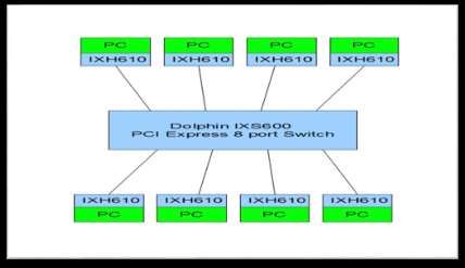
Table of contents
Table of contents ......................................................................................................................................................2
DISCLAIMER ............................................................................................................................................................3
Quick install guide .....................................................................................................................................................4
   IXH610 operating modes ......................................................................................................................................4
   Cable connections ................................................................................................................................................5
Overview ...................................................................................................................................................................6
Dolphin Express adapter card - IXH610 ...................................................................................................................7
   IXH610 high level specification .............................................................................................................................7
   LEDs .....................................................................................................................................................................8
Use cases .................................................................................................................................................................8
   Use case A: Transparent IO .................................................................................................................................8
   Use case B - 2 Node configuration - NTB mode (unbalanced) ............................................................................8
   Use case C - 2 Node Configuration – NTB Mode (Balanced) ..............................................................................9
   Use case D - Switch configuration ........................................................................................................................9
   Use case E – Downstream target ...................................................................................................................... 10
Configuration and DIP-switches ............................................................................................................................ 11
   DIP switch bank SW 1 - SWMODE ................................................................................................................... 12
   DIP switch bank SW 2 – configuration .............................................................................................................. 13
   Use cases summary and settings ...................................................................................................................... 14
Installation .............................................................................................................................................................. 15
   Changing the PCI Express bracket ................................................................................................................... 15
   Installing the adapter card ................................................................................................................................. 15
   Installing and removing the cable ...................................................................................................................... 15
EEPROM Programming......................................................................................................................................... 15
Software installation ............................................................................................................................................... 16
Identifying the card ................................................................................................................................................ 16
Support .................................................................................................................................................................. 17
Technical information............................................................................................................................................. 18
Compliance and regulatory testing ........................................................................................................................ 20
   EMC compliance ................................................................................................................................................ 20
   RoHS compliance .............................................................................................................................................. 20
Flammability standard............................................................................................................................................ 20
Limited warranty .................................................................................................................................................... 21
   Warranty Period ................................................................................................................................................. 21
   Coverage ........................................................................................................................................................... 21
   Service procedure .............................................................................................................................................. 21
   Limitations .......................................................................................................................................................... 21

IXH610 Users Guide – Dolphin Interconnect Solutions                                                                                                  Page 2
DISCLAIMER
DOLPHIN INTERCONNECT SOLUTIONS RESERVES THE RIGHT TO MAKE CHANGES WITHOUT
FURTHER NOTICE TO ANY OF ITS PRODUCTS TO IMPROVE RELIABILITY, FUNCTION, OR DESIGN.
DOLPHIN INTERCONNECT SOLUTIONS DOES NOT ASSUME ANY LIABILITY ARISING OUT OF THE
APPLICATION OR USE OF ANY PRODUCT.

LIFE SUPPORT POLICY

DOLPHIN INTERCONNECT SOLUTIONS’ PRODUCTS ARE NOT AUTHORIZED FOR USE AS CRITICAL
COMPONENTS IN LIFE SUPPORT DEVICES.

ENVIRONMENTAL POLICY

Dolphin is minimizing the amount of printed documentation and software CDs in its shipments, please download
additional documentation and software from www.dolphinics.com/support.

IXH610 Users Guide – Dolphin Interconnect Solutions                                          Page 3
Quick install guide
The IXH610 can be installed in any compliant PCI Express x8 or x16, Gen1, Gen2 or Gen3 slot. The IXH610
does not support slot sizes less than an x8 slot.
Note: Static electricity from your clothes or work environment can damage your PCI Express adapter card or
your PC. Always wear a grounded antistatic wrist strap while opening the PC and when the card is removed
from the anti-static bag.
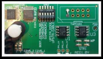
IXH610 operating modes
The Dolphin PCI Express IXH610 card has two
main operational modes, transparent and NTB
mode. The mode is controlled by the BOOT
EEPROM SELECT DIP-switch labeled SW2
that can be found close to the upper edge of
the board. The two mode configuration options
are found in the table below. DIP-switch
position 1 controls setting the board in
transparent or non-transparent mode (NTB).
The DIP-switch can be seen on the picture
below.
Picture 1: DIP Switch SW2 location
Setting SW2 DIP view Configuration
ON Transparent mode
OFF NTB mode
Table 1: Main configuration settings, BOOT EEPROM Select, SW2
All other DIP-switches should normally be left in the factory default setting. More details on DIP-switch settings
can be found on page 10 in this document.
IXH610 Users Guide – Dolphin Interconnect Solutions Page 4Cable connections
The IXH610 requires a x8 iPass™ or PCI Express standard cable. A single x8 cable is used to connect to other
devices including transparent I/O devices, another PC with an IXH610 or IXH620 card, or an IXS600 8 port
switch.
To install they cable, match the male portion on the x8 cable with
the female connector on the IXH610 board. Use even pressure to
insert the connector until it is secure. Adhere to ESD guidelines
when installing the cable ensure not to damage the board. The
IXH610 supports both copper and active fiber cables.
The Dolphin Express IXH610 adapter card is compliant with
Dolphins extensive software package for the IXH adapter card and
the IDT Demo software. Please visit
http://www.dolphinics.com/support to download the latest
documentation and software. Dolphin provides software and
documentation for several product families; please remember to
select the IX product family before downloading.
Picture 2: iPass connector on IXH610
IXH610 Users Guide – Dolphin Interconnect Solutions Page 5Overview
This document describes the new Dolphin PCI Express IX interconnect family and the IXH610 PCI Express
Gen2 adapter card. The card is based on the PES24NT6G2 PCI Express Gen2 chipset from IDT. The IX product
family consists of the following products:
IXH610 PCI Express Gen2 x8 Host adapter card
IXH611 PCI Express Gen2 x8 Host and Target adapter card
IXH620 XMC PCI Express Gen2 Host and Target adapter card
IXS600 8 port PCI Express Gen3 rack mount switch
IXE60X PCI Express expansion products (contact Dolphin for details)
Information on the cabling infrastructure is available at
http://www.dolphinics.com/products/IX_PCI_Express_cables.html
The IXH610 adapter can be used to connect to any of the above products or to any compliant existing PCI
Express downstream device having a standard PCI Express x8 connector (PCI Express Gen 1 or Gen2, auto
detect).
All Dolphin PCI Express IXH adapters support the complete suite of Dolphin NTB Software including Dolphin
SuperSockets™, optimized TCP/IP drivers, and SISCI Embedded software. It is also compliant with the PXImc
software specification.
Dolphin SuperSockets is a Berkeley compliant Sockets library which provides socket latency below 2
microseconds and close to the wire speed streaming bandwidth for networked applications. SuperSockets™ is
currently available on Linux and Windows. It is a 100% transparent plug and play solutions for commercial and
embedded applications. More on SuperSockets can be found at http://www.dolphinics.com/products/dolphin-
supersockets.html
Dolphin’s optimized TCP/IP driver enables PCI Express to be used as a traditional 10G Ethernet / 40G Ethernet
replacement for e.g. NFS sharing and legacy networking that does not need the low latency provided by
SuperSockets. The TCP/IP driver supports gateway functionality.
The SISCI software provides well defined, easy to use shared memory programming API for PCI Express over
cable. More on SISCI can be found at http://www.dolphinics.com/products/embedded-sisci-developers-kit.html
More information about the software provided for the Dolphin IXH adapter cards can be found on
http://www.dolphinics.com/products.
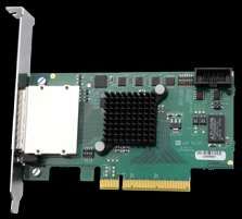
IXH610 Users Guide – Dolphin Interconnect Solutions Page 6Dolphin Express adapter card - IXH610
Illustration 1: Low profile, single PCI Express Gen2 x8 HBA
The IXH610 is a PCI Express Gen2 x8 adapter card available from Dolphin providing an easy to use, multi
functional solution.
IXH610 high level specification
PCI Express Gen2 5.0 Gbps per lane signaling– 40 Gbps total signaling.
PCI Express Gen2 x8 edge connector. The card installs in any PCI Express slot that has a physical x8
or x16 connector.
Compliant with PCI Express Gen1 and Gen3 computers and IO systems, auto detection.
Supports NTB connections to other hosts and transparent connections to IO systems as a transparent
P2P device.
PCI Express Base Specification Rev 2.1
PCI Express External Cabling Specification, Rev. 1.0
One PCI Express Gen2 x8 IPASS Cable connection.
Copper cables tested successfully up to 7 meters
Support for Active Optical Fibers, up to 300 meters.
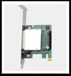
Low Profile - PCI Express Electromechanical Specification, Rev 2.0
Comes with both low profile and standard profile PCI Express bracket.
PIO and Direct DMA capabilities
Host clock isolation. Automatic support for host running CFC or SSC mode.
Support for hot plugging of the PCI Express cable (NTB mode, SISCI and SuperSockets)
Dual 128 KB EEPROM for boot up configuration data.
Optional Software utility for reprogramming of EEPROM content.
No PCI Express power domain isolation.
Full SuperSockets and SISCI compliance via new PAL. Linux and Windows support.
SMbus support.
Power Consumption: 3,3 Volt - Max 7 Watt.
Operating temperature 0°C to 55°C
Relative Humidity 5% - 95% non-condensing
Weight : 80 Gram
JTAG programming and test
RoHS compliant
Compliant to EN-55022, EN 55024-A1&A2, EN 61000-6-2
CE Mark
IXH610 Users Guide – Dolphin Interconnect Solutions Page 7LEDs
The IXH610 cards has two bi-color LEDs visible through the PCI Express front bracket.
LED Dark Yellow Green Green - blinking
Name
Link Power off or failure Power on, Link down Power on, Link Up Power on, Link active, data
transmitted
NTB Transparent Host NA NTB mode NA
mode (PXImc/SISCI/Super
Sockets/TCP/IP
mode)
Table 2: LED overview
The NTB link LED is controlled by software. Both LEDs depends on GPIO registers initialized by EEPROM. An
incorrect EEPROM can cause dark LEDs. DIP-switch SWMODE set to 0000b will cause all LEDs to be dark.
More details on DIP-switch settings can be found below.
Use cases
The IXH610 card may be used in the following use cases. The use cases are summarized in Table 3 Adapter
use cases on page 10.
Use case A: Transparent IO
The Dolphin IXH610 HCA connects to any standardized PCI Express x8 downstream device. No special device
driver is required for the IXH610 card. Any device in the PCI Express IO system will operate using its standard
device driver.
Illustration 2: IXH610 used to connect to a remote PCI Express IO System
Use case B - 2 Node configuration - NTB mode (unbalanced)
2 node unbalanced “NTB” mode- The Dolphin PCI Express IXH610 adapter connects to a remote upstream
subsystem (with root complex) that may have a transparent re-driver card only. This configuration is not
supported by Dolphin software.
IXH610 Users Guide – Dolphin Interconnect Solutions Page 8Illustration 3: Adapter card used to connect to a remote host using a re-driver card.
Use case C - 2 Node Configuration – NTB Mode (Balanced)
Each node has a Dolphin PCI Express IXH610 adapter or Dolphin Express IXH620 XMC adapter direct
connection to remote host using a PCI Express Gen2 x8 cable. This configuration is fully supported by all
Dolphin software.
Illustration 4: Adapter card used to build a two node configuration.
Use case D - Switch configuration
Each node has a Dolphin Express IXH610 adapter or Dolphin Express IXH620 XMC. Up to 8 systems can be
connected to the Dolphin IXS600 8 port PCI Express Gen2 switch.
Illustration 4: Switch use
IXH610 Users Guide – Dolphin Interconnect Solutions Page 9Use case E – Downstream target
The IXH620 XMC adapter or IXH611 PCIe adapter can be used as a downstream target adapter.
Illustration 5: IXS620 as target mode
IXH610 Users Guide – Dolphin Interconnect Solutions Page 10Configuration and DIP-switches
The IXH610 has two banks of DIP switches. The locations of the DIP switches on the cards are shown as SW1
and SW2 on the figure 5 below. The Default factory setting is NTB configuration ( see Use case C - 2 Node
Configuration – NTB Mode (Balanced) and Use case D - Switch configuration, All Dolphin Software using default
setting). The IXH610 will also support transparent use, upstream mode (see Use case A: Transparent IO).
Illustration 6 : IXH610 overview
The IXH610 has DIP-switches for setting special modes or operations. Please carefully read the documentation
before modifying any DIP-switch settings. Please carefully pay attention to ON and OFF positions written on the
DIP switch.
IXH610 Users Guide – Dolphin Interconnect Solutions Page 11DIP switch bank SW 1 - SWMODE
This DIP should normally be kept in factory default mode.
These DIP switches are used to directly control the
PES24NT6G2 Software MODE. Please refer to the
PES24NT6G2 data sheet for details. The most useful options
are documented in the table below.
Picture 3: DIP Switch SW1 location
Binary value – SWMODE [3:0] Description
0000b Single partition, no EEPROM configuration. Supports default
transparent configuration – non optimized settings. No LEDs
operational. This setting can be used to as an emergency setting if an
incorrect or corrupted EEPORM content prevents the system from
booting. Supports reprogramming of the EEPORM.
1100b Default setting. Configuration data in EEPROM.
Illustration 7: SW1 – SWMODE - Default setting
IXH610 Users Guide – Dolphin Interconnect Solutions Page 12DIP switch bank SW 2 – configuration
This DIP Switch is used to configure transparent and non-
transparent modes, set the SMBus address and select the
clock source.
Picture 4: DIP Switch SW2 location
DIP no Name Description ON OFF Default
1 Boot EEPROM Used to select Load configuration Load Off
Select EEPROM 1 or 2 as from EEPROM 2 configuration
boot image. from EEPROM 1
Factory default is
TRANSPARENT Factory default is
Host mode NTB mode
2 and 3 SMBus address Sets the SMBus Off
address to which the
slave SMBus
interface responds.
4 Not used Off
5 Upstream edge off
select
6 Upstream cable Used to select clock Adapter card drives Local clock on
select source and propagate CREFCLK, CRST mode, no CRST
RESET on cable if adapter is on cable
upstream.
Note: Some DIP switch configuration options may be removed in the future versions. Please always consult the
user guide for details.
IXH610 Users Guide – Dolphin Interconnect Solutions Page 13Use cases summary and settings
The table below gives an overview of the various use cases, settings and limitations. SW2 DIP switch settings
not mentioned should be OFF
Use Description SW2 DIP-switch setting Clock source Cable pull Power Software /
case Sequence Driver
requirements
A Downstream – BOOT_EEPROM select Adapter card Not supported IO system No driver
Dolphin adapter ON received by legacy must power required for
card connects to REFCLC from device drivers on first IXH610
downstream IO UPSTREAM_CABLE ON host
card. Legacy
Adapter card drivers for IO
drives Devices
CREFCLK on
cable
B “NTB” BOOT_EEPROM select Adapter card Special System with
OFF receives clock solution IXH610
Dolphin adapter from PCI needed for re- adapter card
card connects to UPSTREAM_CABLE OFF Express cable
driver card need to power
remote re-driver
card side. OS need on first
to support hot
removal.
C Dolphin Host – BOOT EEPROM select Both cards runs Fully No limitations Dolphin
Host. Both OFF on local clock supported SISCI,
connected systems SuperSocket
has Dolphin UPSTREAM_CABLE ON
s, TCP/IP,
adapter card.
PXImc
D Dolphin Switch BOOT_EEPROM select Adapter card Fully No limitations Dolphin
configuration. All OFF transmits clock supported SISCI,
connected hosts on PCI Express SuperSocket
have Dolphin UPSTREAM_CABLE ON cable
s, TCP/IP,
adapter card
PXImc
E Downstream target BOOT_EEPROM select Adapter card Not supported IO system No driver
– Requires an ON receives by legacy must power required for
IXH611 or IXH620 CRECLK from device drivers on first IXH610
adapter. UPSTREAM _EDGE ON cable
card. Legacy
UPSTREAM_CABLE OFF Adapter card drivers for IO
received Devices
REFCLOCK
from expansion
unit
Table 3: Adapter use cases
IXH610 Users Guide – Dolphin Interconnect Solutions Page 14Installation Static electricity from your clothes or work environment can damage your PCI Express adapter card or your PC. Always wear a grounded antistatic wrist strap while opening the PC and when the IXH610 is removed from the anti- static bag. Changing the PCI Express bracket The IXH610 package includes a standard and low profile PCI Express bracket. By default, the standard height bracket is installed on the board, If you need to replace the mounted bracket with a low profile bracket, carefully unscrew the two mounting screws to remove the full height bracket. Save the two mounting screws and replace the bracket with the low profile bracket. Use the two mounting screws to install the low profile bracket. The screws should be carefully tightened. Be careful not to over-tighten. Installing the adapter card Before installing the adapter card, make sure you are properly grounded to avoid static discharges that may destroy your computer or the adapter card. Ensure you are properly grounded before opening your computer or the anti-static bag containing the IXH610.Please follow your computers manual on how to install a PCI Express card. The IXH610 Adapter card can be installed into any PCI Express x8 or x16 slot. The IXH610 supports both PCI Express Gen2 and Gen1 signaling. NOTE: A Gen2 slot is recommended as it typically double the performance compared to a Gen1 slot. The IXH610 is a x8 card so no additional performance can be obtained using a x16 slot. The IXH610 can be installed in a PCI Express Gen3 slot but will operate at Gen2 speed. The IXH610 supports both hosts using spread spectrum and constant frequency clocking. The card implements clock isolation and will provide a high quality CREFCLK signal on the cable. Refer to the DIP switch settings for configuration information. Installing and removing the cable The IXH610 supports PCI Express x8 Gen2 cables. Installing and removing cables should be done with both upstream and downstream device powered off. The Dolphin SuperSockets, TCP/IP drivers and SISCI fully supports hot plugging (Note: installation and removal) of cables while the system is running). Standard PCI Express cables are not designed for a high number of installation and removals; the gold applied to the connector head may wear out and cause loss of communication. Please contact your Dolphin if you intend to continuously connect and disconnect the PCI Express cables. Connecting the cable Please carefully install the PCI Express cable connector into the connector housing on the IXH610 adapter card or IXS600 Switch box. Computer cables should always use stain relief to protect the connected equipment from excessive force via the cable. This is especially important for cables between racks. Disconnecting the cable Please carefully pull back the thumb tab to release the cable from the connector house and pull back the cable. EEPROM Programming Dolphin may from time to time publish updated firmware. Current firmware is normally included in the Dolphin software distribution and published on www.dolphinics.com/support. Please consult the software documentation for information on firmware upgrades or Dolphin support if assistance is required. IXH610 Users Guide – Dolphin Interconnect Solutions Page 15
Software installation
More information on installing Dolphins SuperSockets, SISCI or TCP/IP driver software can be found at
http://www.dolphinics.com/support/installation-ix.html

Identifying the card
The card has a label-sticker with the serial number in the format ‘IXHXXX-YY-ZZZZZZ’, where XXX denotes the
card-type (e.g. 610), YY denotes the card revision (e.g. DE) and ZZZZZZ denotes the serialized production
number (e.g. 012345) – this whole string makes up the serial number of the card (i.e. IXH610-DE-012345).

With the DIS software installed and loaded, you can get this serial number with the ixdiag command;

The top of this output will show information about the card;

Adapter 0 > Type                                        :   IXH610
            NodeId                                      :   4
            Serial number                               :   IXH610-DE-001352
            IXH chipId                                  :   0x8091111d
            IXH chip revision                           :   0x00000002 (ZC)
            EEPROM version NTB mode                     :   0024
            EEPROM version transp mode                  :   0009
            EEPROM swmode[3:0]                          :   1100
            EEPROM images                               :   0001
            Card revision                               :   DE

Here you will see both the whole serial-number string, as well as the decoded card-type and card-revision
identifiers. The ‘EEPROM version NTB mode’ may be of interest – this shows the firmware-version of the card.

You can also get this information without ixdiag (for instance when the drivers are not loaded or the card is in
transparent mode), using lspci in Linux;

First run lspci, and identify the card. It will show up as something like

02:00.0 PCI bridge: Integrated Device Technology, Inc. Device 8091 (rev 02)
02:00.1 Bridge: Integrated Device Technology, Inc. Device 8091 (rev 02)
02:00.2 System peripheral: Integrated Device Technology, Inc. Device 8091 (rev 02)

Second, do an lspci –vvvv –s  , and look for the ‘Serial’ –string

# lspci -s 02:00.0 -vvv | grep Serial
        Capabilities: [180 v1] Device Serial Number 00-00-44-45-00-00-05-48

This shows the card as revision 0x4445 (hexadecimal values of the ‘DE’ letters in the ASCII table), with the
production number 0x00000548 (001352 in decimal).

IXH610 Users Guide – Dolphin Interconnect Solutions                                                Page 16
In Windows, we export the serial number through the event-log through the transparent-mode driver is loaded (v 1.0.1 or later required). This driver is available through the download-section at http://www.dolphinics.com/support/index_support_ix.html PS C:\> Get-EventLog System -Source IXH_T -Newest 1 Index Time EntryType Source InstanceID Message ----- ---- --------- ------ ---------- ------- 34206 Oct 25 23:02 Information IXH_T 1074069505 Serial number is IXH610-CC-000101. Support More information about the product, support and software download can be found at http://www.dolphinics.com. . Please email pci-support@dolphinics.com if you have any questions. IXH610 Users Guide – Dolphin Interconnect Solutions Page 17
Technical information
PCI-Express 8x finger connector pin-out
Pin                  Side B Connector                                                    Side A Connector
#     Name    Description                                 Name         Description
1     +12v    +12 volt power                              PRSNT#1 Hot plug presence detect
2     +12v    +12 volt power                              +12v         +12 volt power
3     RSVD    Reserved                                    +12v         +12 volt power
4     GND     Ground                                      GND          Ground
5     SMCLK   SMBus clock                                 JTAG2        TCK
6     SMDAT   SMBus data                                  JTAG3        TDI
7     GND     Ground                                      JTAG4        TDO
8     +3.3v   +3.3 volt power                             JTAG5        TMS
9     JTAG1   +TRST#                                      +3.3v        +3.3 volt power
10 +3.3V      3.3v volt power                             +3.3v        +3.3 volt power
11 WAKE#      Link Reactivation                           PWRGD        Power Good
                                                      Mechanical Key
12 RSVD       Reserved                                    GND          Ground
13 GND        Ground                                      REFCLK+ Reference Clock Differential pair
14 PETp(0)    Transmitter Lane 0, Differential pair       REFCLK-
15 PETn(0)                                                GND          Ground
16 GND        Ground                                      PERp(0)      Receiver Lane 0, Differential pair
17 PRSNT#2    Hotplug detect                              PERn(0)
18 GND        Ground                                      GND          Ground
19 PETp(1)    Transmitter Lane 1, Differential pair       RSVD         Reserved
20 PETn(1)                                                GND          Ground
21 GND        Ground                                      PERp(1)      Receiver Lane 1, Differential pair
22 GND        Ground                                      PERn(1)
23 PETp(2)    Transmitter Lane 2, Differential pair       GND          Ground
24 PETn(2)                                                GND          Ground
25 GND        Ground                                      PERp(2)      Receiver Lane 2, Differential pair
26 GND        Ground                                      PERn(2)
27 PETp(3)    Transmitter Lane 3, Differential pair       GND          Ground
28 PETn(3)                                                GND          Ground
29 GND        Ground                                      PERp(3)      Receiver Lane 3, Differential pair
30 RSVD       Reserved                                    PERn(3)
31 PRSNT#2    Hot plug detect                             GND          Ground
32 GND        Ground                                      RSVD         Reserved
33 PETp(4)    Transmitter Lane 4, Differential pair       RSVD         Reserved
34 PETn(4)                                                GND          Ground
35 GND        Ground                                      PERp(4)      Receiver Lane 4, Differential pair
36 GND        Ground                                      PERn(4)
37 PETp(5)    Transmitter Lane 5, Differential pair       GND          Ground
38 PETn(5)                                                GND          Ground
39 GND        Ground                                      PERp(5)      Receiver Lane 5, Differential pair
40 GND        Ground                                      PERn(5)
41 PETp(6)    Transmitter Lane 6, Differential pair       GND          Ground
42 PETn(6)                                                GND          Ground
43 GND        Ground                                      PERp(6)      Receiver Lane 6, Differential pair
44 GND        Ground                                      PERn(6)
45 PETp(7)    Transmitter Lane 7, Differential pair       GND          Ground
46 PETn(7)                                                GND          Ground
47 GND        Ground                                      PERp(7)      Receiver Lane 7, Differential pair
48 PRSNT#2    Hot plug detect                             PERn(7)
49 GND        Ground                                      GND          Ground
IXH610 Users Guide – Dolphin Interconnect Solutions                                                         Page 18
PCIe iPass cable connector pin-out PIN# Row A signal name Row B signal name 1 GND GND 2 PETp(0) PERp(0) 3 PETn(0) PERn(0) 4 GND GND 5 PETp(1) PERp(1) 6 PETn(1) PERn(1) 7 GND GND 8 PETp(2) PERp(2) 9 PETn(2) PERn(2) 10 GND GND 11 PETp(3) PERp(3) 12 PETn(3) PERn(3) 13 GND GND 14 CREFCLOCK+ +3,3V POWER 15 CREFCLOCK- +3,3V POWER 16 GND +3,3V POWER 17 RESERVED POWER RET 18 RESERVED POWER RET 19 SIDEBAND RETURN POWER RET 20 CPRESNT# CWAKE#1 21 CPWRON CPERST# 22 GND GND 23 PET(p4) PERp(4) 24 PET(n4) PERn(4) 25 GND GND 26 PET(p5) PERp(5) 27 PET(n5) PERn(5) 28 GND GND 29 PETp(6) PERp(6) 30 PETn(6) PERn(6) 31 GND GND 32 PETp(7) PERp(7) 33 PETn(7) PERn(7) 34 GND GND 1 CWAKE is optional and not used on IXH610 IXH610 Users Guide – Dolphin Interconnect Solutions Page 19
Compliance and regulatory testing

EMC compliance
The Dolphin PCI Express IXH610 adapter has been tested and found to comply with the
following relevant test standards for PCI Express cards, Telecommunication and Industry
equipments installed in a standard PC:

EN 55022 (2010)
EN 55024 (1998) + A1 (2001) + A2 (2003)
EN 61000-6-2 (2005)

This does not ensure that it will comply with these standards in any random PC. It is the responsibility of the
integrator to ensure that their products are compliant with all regulations where their product will be used.

RoHS compliance
The Dolphin IXH610 is RoHS compliant. A compliance certificate issued by the Manufacturer
is available upon request.

Flammability standard
The Dolphin IXH610 PWB is UL94V-0 compliant. The board has the 94V-0 mark in its silk screen.

WEEE Notice
This IXH610 is labelled in accordance with European Directive 2002/96/EC concerning waste
electrical and electronic equipment (WEEE). The Directive determines the frame work for the
return and recycling of used appliances as applicable throughout the European Union. This
label is applied to various products to indicate that the product is not to be thrown away, but returned to your
local approved WEEE waste collector.

IXH610 Users Guide – Dolphin Interconnect Solutions                                                 Page 20
Limited warranty
Dolphin Interconnect Solutions warrants this product to be free from manufacturing defects under the
following terms:
Warranty Period
Dolphin warrants the product for one (1) year from the date of purchase. Extended warranty is available.
Coverage
To the extent permitted by applicable law, this warranty does not apply to:
Damages caused by operator error or non-compliance with instructions available for the product.
Use or attempt to use or program firmware not approved by Dolphin.
Damage which results from accident, abuse, misuse, neglected improper handling or improper
installation; moisture, corrosive environments, high voltage surges, shipping or abnormal working
conditions.
Damages caused by acts of nature, e.g. floods, storms, fire, or earthquakes.
Damage caused by any power source out of range or not provided with the product.
Normal wear and tear.
Attempts to repair, modify, open or upgrade the product by personnel or agents not authorized by
Dolphin.
Products for which the products serial number has been tampered with or removed.
Damage to the product caused by products not supplied by Dolphin.
Service procedure
In the event that the product proves defective during the Warranty Period, you should contact the seller that
supplied you with the product, or if you purchased it directly from Dolphin, email
returnrequests@dolphinics.com to obtain a valid RMA number and instructions. Products returned to Dolphin
without a proper RMA number will not be serviced under this warranty.
Limitations
TO THE FULLEST EXTENT PERMITTED BY LAW, DOLPHIN WILL NOT BE LIABLE FOR ANY
INDIRECT, INCIDENTAL, SPECIAL OR CONSEQUENTIAL DAMAGES (INCLUDING LOST
PROFITS, LOST DATA, OR LOSS OF USE) ARISING OUT OF ANY USE DOLPHINS PRODUCTS,
SOFTWARE OR SERVICE PROVIDED. DOLPHINS MAXIMUM LIABILITY WILL NOT EXCEED THE
TOTAL AMOUNT PAID FOR THE PRODUCT BY PURCHASER.
IXH610 Users Guide – Dolphin Interconnect Solutions Page 21You can also read