DRAFT Regional Draughting Manual for Water Services - April 2021 Version 1.2
←
→
Page content transcription
If your browser does not render page correctly, please read the page content below
[DRAFT] Regional Draughting
Manual for Water Services
April 2021 Version 1.2

                     Page 1 of 19   DRAFT Regional Draughting Manual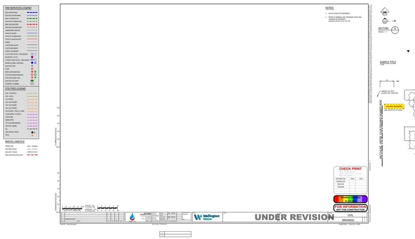
Document Control
This document was developed for the Hutt, Porirua, Upper Hutt and Wellington City Councils, South
Wairarapa District Council and Greater Wellington Regional Council.

Revision History
 Revision Nº    Prepared By              Description                                        Date
 A              Andy McLaughlin          Preliminary Issue for panel review                 07/2018
 B              Andy McLaughlin          Updated Issue for panel review                     10/2018
 C              Steve Robson             Format and review updates included                 10/2018
 D              Andy McLaughlin          Issue for final review                             02/2019
 1              Steve Robson             Approved and issued                                02/2019
 1.1            Steve Robson             Updated and aligned with As-Built Specification    06/2019
 1.2            Dylan Hopkins, Wade      Reviewed and updated to align with refreshed       03/2021
                Gosper, Steve Luck       Regional As-Built Specification (RABS), Regional
                                         Standard for Water Services (RSWS) and
                                         Regional Specification for Water Services
                                         (R.Spec)

Document Acceptance
 Company                          Action                     Name                       Date
 Panel – CAD Managers             Prepared by                Andy McLaughlin            August 2018
 Andy McLaughlin (CW)
 Sharon Seath (GHD)
 Jim Hunt (Stantec)
 Duran Middleton (CW)
 Chris Flynn (CW)
 Connect Water Ltd                Approved by                Malcolm Franklin           Feb 2019
 GHD Ltd                          Approved by                Craig Brown                Feb 2019
 Stantec Ltd                      Approved by                Dougal Wilson              Feb 2019
 Wellington Water Ltd             Approved by                Steve Robson               Feb 2019

                                      Page 2 of 19                            DRAFT Regional Draughting Manual
Table of Contents
1.     Introduction ............................................................................................................................................................ 5
     1.1       Purpose ...................................................................................................................................................................... 5
     1.2       Objectives ................................................................................................................................................................... 5
     1.3       Scope .......................................................................................................................................................................... 5
     1.4       Coordinates and Datum ............................................................................................................................................. 6
     1.5       Hand Sketches ............................................................................................................................................................ 6
2.     Drawing Set-up ....................................................................................................................................................... 6
     2.1       Drawing Template ...................................................................................................................................................... 6
     2.2       Drawing Issue Format................................................................................................................................................. 6
3.     Draughting Standards ............................................................................................................................................. 6
     3.1       Sheet Sizes .................................................................................................................................................................. 6
     3.2       Drawing Scales............................................................................................................................................................ 7
       3.2.1       Indication of Scales ................................................................................................................................................ 7
       3.2.2       Exaggerated Scales ................................................................................................................................................ 7
     3.3       Layer Naming.............................................................................................................................................................. 7
     3.4       Line Thickness and Spacing ........................................................................................................................................ 7
     3.5       Line Type .................................................................................................................................................................... 7
     3.6       Plot Styles ................................................................................................................................................................... 8
     3.7       Pen Assignments ........................................................................................................................................................ 8
     3.8       Dimensioning.............................................................................................................................................................. 8
       3.8.1       Dimension Style ..................................................................................................................................................... 8
       3.8.2       Angular Dimensions ............................................................................................................................................... 8
     3.9       Notation ..................................................................................................................................................................... 8
       3.9.1       Text Styles .............................................................................................................................................................. 9
       3.9.2       Thickness of Character Lines .................................................................................................................................. 9
       3.9.3       Notes...................................................................................................................................................................... 9
       3.9.4       General Notes ........................................................................................................................................................ 9
       3.9.5       Position of Notations ............................................................................................................................................. 9
     3.10      Drawing Presentation ............................................................................................................................................... 10
       3.10.1          Cross Referencing ............................................................................................................................................ 10
       3.10.2          Titles ................................................................................................................................................................ 10
       3.10.3          Sections and Details ........................................................................................................................................ 10
     3.11      Drawing Stamps........................................................................................................................................................ 10
4      Drawing Sets ......................................................................................................................................................... 10
5      Printing and Issuing Drawings ............................................................................................................................... 11
     5.1       Printing – to PDF and from PDF ................................................................................................................................ 11
     5.2       Signatures ................................................................................................................................................................. 11
     5.3       Revisions................................................................................................................................................................... 11
     5.4       Transmittal Notices .................................................................................................................................................. 12
6      As Built Process & Documentation ....................................................................................................................... 12

                                                                          Page 3 of 19                                                      DRAFT Regional Draughting Manual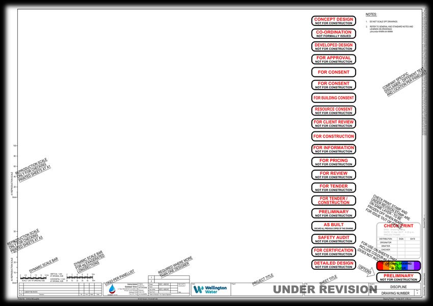
7        3D Models............................................................................................................................................................. 12
Appendices ..................................................................................................................................................................... 13
    A.      Coversheet Template Example ..................................................................................................................................... 14
    B.      Drawing Border Template Example .............................................................................................................................. 15
    C.      Drawing Border Explanation ......................................................................................................................................... 16
    D.      Drawing Border Extras .................................................................................................................................................. 17
    E.      Example Standard Notes Sheet ..................................................................................................................................... 18
    F.      Long Section Example ................................................................................................................................................... 19

                                                                           Page 4 of 19                                                   DRAFT Regional Draughting Manual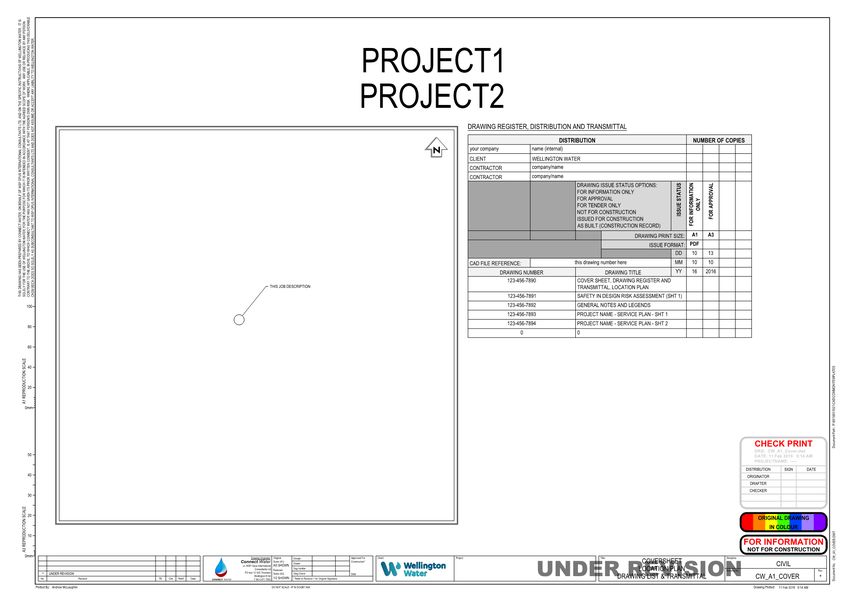
1. Introduction
The Regional Draughting Manual is a guide that primarily provides technical information for the production
of drawings for the Wellington Water Limited (Wellington Water) Consultancy Panel being GHD Ltd, Stantec
Ltd and Connect Water Ltd. It is also a key reference document for other companies that provide
Draughting services for, or on behalf of, Wellington Water.
This Manual is to be read in conjunction with the Regional Standard for Water Services (RSWS), the
Regional Specification for Water Services (RSWS) and the Regional As-Built Specification for Water Services
(RABS) all available at www.wellingtonwater.co.nz.

1.1 Purpose
This document outlines the objectives and procedures for the preparation of drawings for all disciplines on
Wellington Water projects.
The creation of drawings involves creating, maintaining, controlling and sharing reference files and design
models (if applicable). This document also outlines the standards and procedures that are to be adhered to.

1.2 Objectives
The objectives of the drawing production are:
• to produce cost effective drawings;
• to accurately portray the design intent;
• to produce drawings which are consistent with the intended use; and
• to provide clear, consistent documentation which is easily understood by users and minimises requests
    for additional information from Contractors.
Key steps to meeting these objectives include:
• producing a cartoon set to define the content on each sheet, the number of drawings within the set,
    programme and budgeting prior to starting the drawings;
• establishing the level of information required for the purpose (i.e. preliminary drawings to confirm the
    concept design versus detailed design drawings for a contractor to construct from);
•   focusing on multidisciplinary co-ordination; and
•   remembering that drawings define scope and specifications define quality.

1.3 Scope
This procedure applies to all drawings / CAD files and models prepared for Wellington Water and covers:
• Drawing setup
•   Draughting standards
•   Drawing Issue Sets
•   Printing and issuing of drawings
•   3D models
Drawings created are to follow appropriate best practice, and appropriate company drafting procedures to
produce a consistent drawing standard with other Wellington Water Consultancy Panel detail design
drawings.

                                          Page 5 of 19                          DRAFT Regional Draughting Manual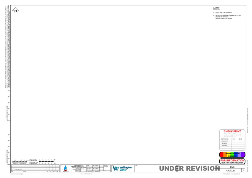
1.4 Coordinates and Datum
The following coordinate system and datum shall be used for all Project drawings:
• Coordinate system New Zealand Transverse Mercator 2000.
• Datum Mean Sea Level Datum Wellington 1953.
Note: Wellington Water is in the process of migrating to the NZVD2016 standard and will provide an update
to this manual once adopted. NZVD2016 levels can be submitted to Wellington Water before it is fully
adopted.

1.5 Hand Sketches
Once construction is underway, the site design team may be required to create hand sketches.
Once verified and complete a hard copy is to be filed and a PDF is to be created for issue to Wellington
Water.

2. Drawing Set-up
Drawings produced and issued for the construction, or maintenance of water service infrastructure assets
within Wellington Water’s jurisdiction are to be of a sound engineering draughting standard.

2.1 Drawing Template
In order to meet the requirements indicated in section 3 below, a standard drawing template is available
from Wellington Water to support these standards. It is envisaged that this template will be used and that
each company will insert their own company logo and details.
Ref: WW file name: WWL_A1_Cover.dwt and WWL_A1_H.dwt = *.dwt
Other Standard drawing support files for the print set ups, drawing list spreadsheet and print files can be
found in the attached zip file AutoCAD files.zip embedded into this document below.

    AutoCAD Files.zip

The panel company lead draughtsperson shall ensure Wellington Water project template files are
maintained in a specific location that all draughters can access within their organisation.

2.2 Drawing Issue Format
•    Each drawing shall have a unique drawing number. This also applies to cad files that contain multiple
     layout tabs for multiple drawings (as often used for General Arrangements and Longitudinal Sections).
•    When multiple layout tabs / multiple drawings are used, the CAD file name should reflect the range of
     drawings (e.g. WWL-100_110.dwg contains drawings WWL-100 thru WWL-110).
•    The drawing titles 3rd line should indicate if a drawing is part of a set (e.g. sheet 1, sheet 2 etc).

3. Draughting Standards
3.1 Sheet Sizes
•    Within the CAD environment, the original sheet size for all drawings is A1 (841 x 594mm).

                                              Page 6 of 19                           DRAFT Regional Draughting Manual
• Drawings are to be reduced to A3 size for record and issue, unless specifically requested.
• Schematics, electrical drawings and process and instrumentation drawings should be A3, with print
easily legible at that size for ease of plant maintenance and operations.
3.2 Drawing Scales
The scale for a drawing shall permit easy and clear interpretation of the information depicted.
Scales for both A1 and A3 (reduced) prints shall be included on the drawing. A dynamic scale bar with
common scales is provided in the template (*.dwt) file referenced in section 2.1.
3.2.1 Indication of Scales
• Where all scales on a single drawing are the same, indicate the scale used for A1 in the title block and
indicate half of the scale used for A3 (e.g. 1:250 (A1) 1:500 (A3)).
• If scales differ on a single drawing, put “AS SHOWN” for A1 in the title block and “1/2 SHOWN” for A3.
• Where it is necessary to have a detail not drawn to scale, then in place of the ratio scale the title shall
read N.T.S (meaning not to scale).
• In all instances place the scale in the Section or Detail title.
3.2.2 Exaggerated Scales
• Where different scales are used for horizontal and vertical dimensions, such as in long sections, then
each scale shall be shown with a prefix of either HORIZ or VERT.
• The exaggerated scale shall clearly show grades, high and low points, existing features and services,
proposed pipeline and equipment etc.
• An exaggerated dynamic scale bar with common scales is provided in the template (*.dwt) file
referenced in section 2.1.
• The long section table shall follow the format shown in the sample included in the Appendix of this
Manual.
3.3 Layer Naming
Each layer shall be given a descriptive name such that another draughtsperson may easily interpret it (e.g. a
road kerb is to be called “Kerb”).
3.4 Line Thickness and Spacing
The thickness of a line shall be such that when the drawing is reduced or reproduced, the lines are still
clearly legible.
3.5 Line Type
These are to be set by layer as appropriate. The standard line types and colours are provided in the legend
of the title block template file in AutoCAD (*.dwt) format as shown in the sample included in the Appendix
of this Manual.
Type AutoCAD Colour RGB code
Potable / Water supply 160 (blue) 0, 63, 255
Wastewater 10 (red) 255, 0, 0
Page 7 of 19 DRAFT Regional Draughting ManualType AutoCAD Colour RGB code
Stormwater 94 (green) 0, 129, 0
Gas N/A (Olive) 143, 143, 0
Communications 200 (Purple) 192, 0, 255
Power 30 (Orange) 255, 127, 0
Kerb lines 11 (Pink) 255, 127, 127
Property boundaries 0 (Black) 0, 0, 0
3.6 Plot Styles
Two plot style table files (ctb) shall be used depending on the plot size as follows:
Plot Style Name Plot Size
WW_A1.ctb A0 & A1
WW_A1-A3.ctb A3 & A4
3.7 Pen Assignments
Pen weights are to be assigned by layer.
3.8 Dimensioning
Dimensions and lettering shall read from the bottom or right-hand side of the drawing sheet.
3.8.1 Dimension Style
The dimension settings are in the dimension style called “STANDARD” and is the only dimension style that is
to be used. It is loaded in the drawing templates (*.dwt). This maintains uniformity across all drawn
documents.
3.8.2 Angular Dimensions
Angular dimensions shall be expressed in decimal degrees.
3.9 Notation
Each necessary note to convey the designer’s intentions of an end product shall be specified. No more
notes than those necessary for complete definition shall be given. The recommended minimum height of
characters on drawings are indicated in the table below:
Character use Character height (A1)
Hold labels, important text 7mm
Title designations, title descriptions 5mm
Subtitles, headings, view & section/detail designations (cross reference sheet number) 3.5mm
General notes, typical text 3mm
View & section/detail reference (cross reference sheet number) 2.5mm
Page 8 of 19 DRAFT Regional Draughting Manual3.9.1 Text Styles
There are currently three text styles loaded into standard template drawings as follows:
Text style Font name Width factor For use as
Arial Black Arial Black 1 Street names and watercourses
STANDARD Arial Narrow 1 All other text
ISO Arial Narrow 1 All other text
NB .SHX fonts may not be used – Notation including asset numbers created with .SHX fonts cannot be searched for
once files are converted to PDF.
3.9.2 Thickness of Character Lines
The thickness of characters shall be as follows:
Text Height AutoCAD Colour RGB code
3 2 (Yellow) 255, 255, 0
3.5 2 (Yellow) 255, 255, 0
5 3 (Green) 0, 255, 0
7 4 (Cyan) 0, 255, 255
2.5 7 (White) 255, 255, 255
3.9.3 Notes
• Text shall be uppercase, top and left justified as a general preference.
• Leaders and text justification shall be consistent throughout the project.
• A leader shall be used to point to the feature concerning that note.
3.9.4 General Notes
Where information needs to be noted concerning the entire drawing, then general notes shall be added
(there should be clearly numbered). The first note shall always be “DO NOT SCALE OFF DRAWINGS”.
Where information needs to be noted concerning the entire series of drawings, then a sheet containing
general notes shall be added to the beginning of the series (note, series refers to a group of sequentially
numbered sheets in a single sub-discipline).
3.9.5 Position of Notations
Within a set of drawings, the location of the items below is to be consistent. The recommended position of
notations shall be as follows:
Notation Type Position
North Point Top right
Key Plan Top left
General Notes & Legend Right
Status Stamp Bottom right
Page 9 of 19 DRAFT Regional Draughting Manual3.10 Drawing Presentation
• Drawings should show the amount of detail necessary for the purpose.
• All plans shall preferably be orientated south towards the left and north towards the right.
• All drawings shall be drawn with the same orientation.
• Sections and elevations should be chosen to show the most appropriate amount of detail.
• All plans, sections and details must be clearly and uniquely identified.
• Duplication of information on a set of drawings should be avoided as this can lead to ambiguities should
changes occur.
3.10.1 Cross Referencing
When referencing a detail on another drawing with a detail call-out, use the drawing number only.
3.10.2 Titles
Where sections or details do not appear on the same sheet as the section markers or detail callout, then a
reference shall be added by inserting the relevant drawing number in the bottom half of the title.
Otherwise use a hyphen for same sheet referencing.
• The title should give a brief description of the detail. A scale note shall be shown under the title.
• Titles should be laid out in an orderly flowing manner, so the reader can easily find information.
Note: Titles on plans do not require a reference ball unless they are a partial plan.
3.10.3 Sections and Details
Section and detail symbol blocks are embedded in the title block template for ease of use. Numbers or
letters shall be used as the section and detail designations to your company’s preference, and this must be
consistent throughout the set.
3.11 Drawing Stamps
Each Drawing shall include a drawing stamp in the bottom right of the sheet.
The drawing template (*.dwt) files include a dynamic stamp which has typical approved stamps, and a
colour stamp.
The colour stamp with the words “Original Drawing in Colour” shall be used where the drawing contains
colour represented items (e.g. aerials, services). It is not required if the drawing only contains a coloured
logo).
Two further stamps are supplied with the template (*.dwt) files referenced in section 2.1:
• ‘Under Revision’ watermark which should be:
o Off for formal issues (generally out of office),
o On at all other times.
Note: turn off and on by freezing/thawing the layer Border-013, do not unlock the layer.
• Manual ‘Check Box’ Stamp - to be used for internal checking. This stamp is on same layer as above, and
therefore is off for formal issues.
4 Drawing Sets
The completed drawing set for a project shall include, in order, the following:
Page 10 of 19 DRAFT Regional Draughting ManualCover sheet including Project Title, Location Plan, Transmittal (Appendix A)
• The transmittal is a spreadsheet (can be linked), that includes a complete listing of the project
documents, issue, size and date, recipients and reason for issue. It is provided in the AutoCAD (*.dwt)
coversheet template file.
• The only reason to not use the transmittal on the coversheet would be for projects that contain a very
large number of documents. In this instance the transmittal is to be on subsequent drawing sheets.
Safety in Design Health & Safety Risk Assessment sheet(s) (SID) (A Project deliverable)
• The completed Wellington Water SID spreadsheet(s) should be copied into the drawing sheet(s), not
linked, so that the correct colouration is displayed. This applies to AutoCAD, for Revit use Ideat’s
Bimlink addon.
• Only one SID page per drawing sheet should be included for legibility.
Standard Notes, Abbreviations and Legends sheet(s) (Appendix E)
• Examples of these are provided for use and include various special notes for existing services etc.
• These notes sheets will be kept as uniform as possible with addition of project specific notes as
required.
Alignment plans / longitudinal Sections sheet(s) (Appendix F)
• The use of faded aerials as background is accepted.
• Longitudinal sections shall follow the format as indicated in the example included in the Appendix of
this Manual.
• Project design details (as required)
• Sets may include separate sections as required for (but not limited to) civil, structural, electrical,
mechanical.
• Drawing number conventions to follow individual company standards.
5 Printing and Issuing Drawings
5.1 Printing – to PDF and from PDF
• Plot to PDF using ‘DWG to PDF’ within the AutoCAD plotting environment without layers and to scale.
• Hardcopy prints are made from those PDF’s. Do not use ‘print to fit’.
• Plot using views in Paperspace. These views are predefined in the Template files.
• Pen weights / colour dependent Plot Style Tables (CTB) files are included in the setup and should be
accessible by AutoCAD to provide consistent plot outputs. (refer section 3.6 and 3.7 of this Manual).
• The PDF name shall match the DWG name (e.g. xyz.dwg and xyz.pdf). It is acceptable to add the
revision number (e.g. xyz Rev1.pdf).
5.2 Signatures
Before any drawing is issued, the correct approval signatures must be present as per company procedures.
5.3 Revisions
Each drawing when issued must have a new revision letter / number and revision and/or hold clouds as
required. Issue types include:
Page 11 of 19 DRAFT Regional Draughting Manual• Preliminary issues, for information: A, B, C etc.
• For Tender: 0 (zero), 0A, 0B etc.
• For Building Consent, For Construction 1, 2, 3 etc.
• As Built: AB
5.4 Transmittal Notices
A document transmittal shall accompany all external issued drawings (the first drawing sheet in a project
set shall include this transmittal). Refer to the template referenced in section 2.1, and the example shown
in Appendix A of this Manual. It is the responsibility of the draughter to maintain this prior to issuing.
6 As Built Process & Documentation
Refer to the Wellington Water Limited - Regional As-Built Specification (RABS) document, available at
https://www.wellingtonwater.co.nz.
7 3D Models
3D Design Models including, but not limited to, Civil 3D, MX, 12D, Revit are to be delivered on request to
Wellington Water. Inclusions shall be discussed with the requester prior to delivery.
Page 12 of 19 DRAFT Regional Draughting ManualAppendices
The following pages provide the expected drawing sheet details to be included on all drawings submitted to
Wellington Water.
A. Coversheet template example
B. Drawing border Template example
C. Drawing border explanation
D. Drawing border extras
E. Example standard notes sheet
F. Long section example
Page 13 of 19 DRAFT Regional Draughting ManualA. Coversheet Template Example
Page 14 of 19 DRAFT Regional Draughting ManualB. Drawing Border Template Example
Company Disclaimer
(Connect Water shown)
The Company Logo and Disclaimer are the only
differences between Panelist drawing sheets
Company Logo
(Connect Water shown)
Page 15 of 19 DRAFT Regional Draughting ManualC. Drawing Border Explanation
Page 16 of 19 DRAFT Regional Draughting ManualD. Drawing Border Extras
Refer to the dwg file for explanatory notes (on non-print
defpoints layer) for items shown outside the border
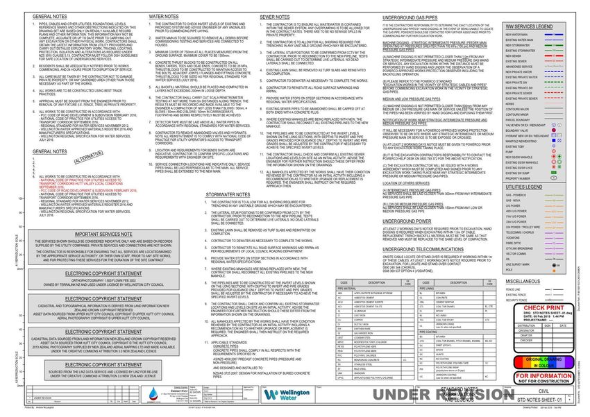
Page 17 of 19 DRAFT Regional Draughting ManualE. Example Standard Notes Sheet
Page 18 of 19 DRAFT Regional Draughting ManualF. Long Section Example
The long section shall use a ‘top down’ convention as shown above, where items are listed from the highest level to the lowest level by row, followed by
information rows. When using 3D software, templates need to reflect this format.
Page 19 of 19 DRAFT Regional Draughting ManualYou can also read