Force / Sensor 2019 Owner's Manual Supplement - GT Bicycles

Page created by Kathy Harvey
 
CONTINUE READING
Force / Sensor 2019 Owner's Manual Supplement - GT Bicycles
2019

         Force / Sensor
         Owner’s Manual Supplement

READ THIS SUPPLEMENT AND YOUR
GT BICYCLE OWNER’S MANUAL. Both
contain important safety information. Keep
both for future reference.
Safety Messages
               In this supplement, particularly important information
                          is presented in the following ways:

                        Indicates a hazardous situation
                        which, if not avoided, may result in
                        death or serious injury.

                        NOTICE
                        Indicates special precautions that
                        must be taken to avoid damage.

                  The following symbols are used in this manual:

Symbol                  Name               Description
  NG
      LI
         -2     NGLI-2 synthetic grease    Apply NGLI-2 synthetic grease.

 CR
   B-
        GE
           L          Carbon gel           Apply carbon gel (friction paste) KF115/

                  Medium-strength
      2                                     Apply Loctite® 242 (blue) or equivalent.
                removable thread lock
English

 GT Supplements
 This manual is a “supplement” to your
                                                             CONTENTS
 GT Bicycle Owner’s Manual.
                                              Safety Information.....................................2-6
 This supplement provides additional
 and important model specific                 Technical Information........................... 7-19
 safety, maintenance, and technical
 information. It may be one of several        Replacement Parts..............................20-21
 important manuals/supplements
                                              Tightening Torques.....................................22
 for your bike; obtain and read all of
 them.                                        Maintenance.................................................... 23
 Please contact your Authorized GT            Notes......................................................................24
 Dealer immediately if you need a
 manual or supplement, or have a
 question about your bike. You may
 also contact us using the appropriate
 country/region/location information.
 You can download Adobe Acrobat
 PDF versions of any manual/
 supplement from our website:
 http://www.gtbikes.com.                      Your GT Dealer
                                              To make sure your bike is serviced
 Contacting GT                                and maintained correctly, and that
 GT USA                                       you protect applicable warranties,
 Cycling Sports Group, Inc.                   please coordinate all service
 1 Cannondale Way, Wilton CT,                 and maintenance through your
 06897, USA                                   Authorized GT Dealer.
 1-800-726-BIKE (2453)
                                                NOTICE
 Cycling Sports Group Europe B.V
 Mail: Postbus 5100                             Unauthorized service,
 Visits: Hanzepoort 27                          maintenance, or repair parts can
 7570 GC, OLDENZAAL, Netherlands                result in serious damage and void
 Tel: +41 61 551 14 80                          your warranty.
 Fax:+31 54 151 42 40
 International Distributors
 Consult the following websIte to
 identify the appropriate GT Dealer for
 your region.

134937 Rev 1.                             1
Force / Sensor - Owners Manual Supplement

                         SAFETY INFORMATION

 Important Composites                        Inspection & Crash
 Message                                     Damage Of Carbon
                                             Frames/Forks

   Your bike (frame and components)
   is made from composite materials
                                             After A Crash Or Impact:
   also known as “carbon fiber.”
                                             Inspect frame carefully for
   All riders must understand a
                                             damage (See PART II, Section D.
   fundamental reality of composites.
                                             Inspect For Safety in your
   Composite materials constructed
                                             GT Bicycle Owner’s Manual. )
   of carbon fibers are strong and
   light, but when crashed or                Do not ride your bike if you see any
   overloaded, carbon fibers do not          sign of damage, such as broken,
   bend, they break.                         splintered, or delaminated carbon
                                             fiber.
   For your safety, as you own and
   use the bike, you must follow             Any of the following may indicate
   proper service, maintenance, and          a delamination or damage:
   inspection of all the composites
                                             ·   An unusual or strange feel to
   (frame, stem, fork, handlebar, seat
                                                 the frame
   post, etc.) Ask your GT Dealer for
                                             ·   Carbon which has a soft feel or
   help.
                                                 altered shape
   We urge you to read PART II,              ·   Creaking or other unexplained
   Section D. “Inspect For Safety” in            noises,
   your GT Bicycle Owner’s Manual            ·   Visible cracks, a white or milky
   BEFORE you ride.                              color present in carbon fiber
                                                 section
   You can be severely injured,
   paralyzed or killed in an accident
                                             Continuing to ride a damaged
   if you ignore this warning.
                                             frame increases the chances of
                                             frame failure, with the possibility
                                             of injury or death of the rider.

134937 Rev 1.                            2
English

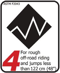
 Intended Use                             Servicing

                The intended use of
                all models is ASTM
                CONDITION 4,               This supplement may include
                All-Mountain.              procedures beyond the scope of
                                           general mechanical aptitude.
                                           Special tools, skills, and knowledge
                                           may be required. Improper
                                           mechanical work increases the
                                           risk of an accident. Any bicycle
  Understand your bike and its             accident has risk of serious injury,
  intended use. Using your bike the        paralysis or death.
  wrong way is dangerous.                  To minimize risk we strongly
  Please read your GT Bicycle              recommend that owners always
  Owner’s Manual for more                  have mechanical work done by
  information about Intended Use           an Authorized GT Dealer.
  and Conditions 1-5.

134937 Rev 1.                         3
Force / Sensor - Owners Manual Supplement

Maximum Fork Length
Maximum Fork Length is an important frame safety testing specification for front
suspension mountain bikes. You must observe the measurement when installing
headset parts, headset adapters, installing and adjusting a fork, and selecting
replacement forks.

                                          From
                                     Bottom Of Frame
                                        Head Tube

                                                  Maximum
                                                  Fork
                                                  Length

                                                       To Center Of
                                                       The Fork Axle

 You must select a replacement fork not only based on head tube diameter but the
 critical factor of frame maximum fork length
 Do not exceed maximum fork length. Exceeding the MAXIMUM FORK LENGTH limit
 can overload the frame causing it to break while riding.
 Your retailer MUST follow and observe this specification for your bike. For Maximum Fork
 Length specifications for GT bicycles, see www.gtbikes.com.
 You can be severely injured, paralyzed or killed in an accident if you ignore this
 warning.

134937 Rev 1.                                4
English

 Tire Size x Maximum Width

   Observe the Tire Size x Maximum Width for your bike found in the
   “Specifications” page of this manual.
   Mounting the wrong size tires can result in the tires hitting the fork or frame
   when riding. If this happens, you can lose control of your bike and you can be
   thrown off, a moving tire can be stopped because it touches the fork or frame.
   Do not mount oversized tires, ones that rub or hit the fork or frame, ones that
   result in too little clearance, or ones that can hit the fork or frame when the
   suspension is fully compressed or when riding.
   Take care that the tires you select are compatible with your bike’s fork or frame
   design. Also, be sure to follow the manufacturer’s recommendations of your
   front fork and rear shocks.
   When you are considering tires for your bike consider...
   The actual measured size of a tire may be different than its sidewall marking.
   Each time you mount a new tire, take the time to inspect the actual clearance
   between the rotating tire and all parts of the frame. The U.S. Consumer
   Product Safety Commission (CPSC) requires at least 1/16” (1.6 mm) tire clearance
   from any part of the bike. Allowing for lateral rim flex and a wheel or rim that
   is out-of-true will likely mean choosing a rear tire that provides even more
   clearance than the CPSC recommends.
   Ask your dealer for the right tires for your bike and its particular components!
   You can be severely injured, paralyzed or killed in an accident if you ignore
   this warning.

134937 Rev 1.                           5
Force / Sensor - Owners Manual Supplement

 Rear Shocks                                  Minimum Seat Post Insert

   Select only compatible shocks              Make sure at least 100 mm of
   and forks for your bike. Do not            the seat post is inserted into the
   modify your bike in any way to             frame at all times.
   mount one.
                                              Failure to insert the seat post at
   Have your shock or fork installed          least 100 mm can place a very
   by a professional bike mechanic            high stress on the seat tube top
                                              tube junction causing the frame to
   Riding with the wrong rear shock
                                              fail while riding.
   can damage the frame. You
   could have a serious accident.             Remove the seat post. Measure
   Make sure the total travel, eye-           100 mm from the bottom of
   to-eye length, and stroke length           the seat post. Use a permanent
   of the rear shock you select meet          marker to mark the post at 100
   the “Specifications” listed in this        mm.
   manual.
                                              When adjusting the seat post
   When selecting different shocks            height in the seat tube, never
   or forks for your bike, make sure          adjust the seat post so that the
   that the shock or fork you select is       line you mark is above the top
   compatible with your bike’s design         edge of the seat tube.
   and how you will use your bike.
                                              You must also be aware that
   You can be severely injured,               bicycle seat posts are permanently
   paralyzed or killed in an accident         marked by the manufacturer with
   if you ignore this warning.                a “minimum insert” line on the
                                              seat post itself. You must not rely
                                              on this marking as an indication
                                              of the proper minimum seat post
                                              insertion depth.
                                              You can be severely injured,
                                              paralyzed or killed in an accident
                                              if you ignore this warning.

134937 Rev 1.                             6
English

                     TECHNICAL INFORMATION
Specifications

 Item                                                  Specification
 Model                                        Force                    Sensor
 Wheel Size                                  27.5 in                     29 in
 Rear Travel                                150 mm                     130 mm
 Head Tube                                    UPR: 1-1/8 in, LWR: 1-1/2 in
 Headset                                      Integrated, 1-1/8 in - 1-1/2 in
 Bottom Bracket: Type/ Width                           BSA / 73 mm
 Front Derailleur                                           N/A
 Seat Post: Dia./Binder                           31.6 mm/ 34.9 mm
    Min. Seat Post Insert                                100 mm
   Tire Size x Max. Width
                                         27.5 in x 2.5 in          29 in x 2.35 in
 (measured)
    Max. Fork Length                        550 mm                   540 mm
 Rear Shock: Eye-To-Eye / Stroke /       185 mm x 55 mm           185 mm x 50 mm
 Bushing Width                            Metric Trunnion          Metric Trunnion
 Sag (measured at shock)                    12.5 mm                    12 mm
 Chain Guide                                             ISCG 05
 Rear Brake: Mount Type /                       Post Mount / 180 mm
 Min/Max Rotor Dia.                                   / 203 mm
                                                Maxle TA / 148 x 12mm,
 Rear Axle: Type/Length
                                                   180 mm Length
                                                 ASTM CONDITION 4,
    Intended Use
                                                    All-Mountain
   Max. Weight Limit
                                                      305 lbs / 138 kg
 Total (rider+all equipment):

134937 Rev 1.                        7
Force / Sensor - Owners Manual Supplement

                                                                     C
                                                                             P
             UP
                                                                                                    H

                                                            O

                                           D

                                                                                                                I
                                       B

                                                                                          G
                                                                                                          A

                                                                             L(+)
                                                                 K
                                      E                                                             M                 J
                                                        GROUND
                                                                         F
Dimensions = millimeter

 Geometry - Force 27.5
 Frame Size                                             S                             M                         L                    XL
 Flip Chip Orientation
   D       Seat Tube Length                     400         400               430         430           480         480      520          520

   C       Top Tube Horizontal                 566.46       568              593.27       595       620.09           621    646.9         648

   A       Head Tube Angle                     65.5°         65°             65.5°            65°       65.5°        65°     65.5°        65°

   B       Seat Tube Angle                      76°         75.5°             76°         75.5°         76°         75.5°    76°          75.5°

   G       Standover                           740.4        740.4            750.3        750.3     760.2           760.2    795.1        795.1

   H       Head Tube Length                     102         102               110             110        118         118     126          126

   F       Wheelbase                           116.28        164         1190.60          1192      1218.91         1221    1247.23       1249

   M       Front Center                         730         730               758         758           787         787      815          815

   E       Chainstay Length                    432.4        435              434.4        435           434.4       435     434.5         435

    L      Bottom Bracket Drop                  13.7            20            13.7            20        13.7         20      13.7          20

   K       Bottom Bracket Height               345.3        339              345.3        339           345.3       339      345.3        339

    J      Fork Rake                            44              44               44           44         44          44       44           44

    L      Stack                               587.41        591         594.68           599       601.97          606     609.25        613

   M       Reach                                420          415              445         440           470         465      495          490

All Specifications subject to change without notice.

134937 Rev 1.                                                        8
English

                                                                     C
                                                                             P
             UP
                                                                                                   H

                                                            O

                                           D

                                                                                                              I
                                       B

                                                                                          G
                                                                                                        A

                                                                             L(+)
                                                                  K
                                      E                                                            M                J
                                                         GROUND
                                                                         F
Dimensions = millimeter

 Geometry - Sensor 29
 Frame Size                                             S                             M                       L                  XL
 Flip Chip Orientation
   D       Seat Tube Length                     392         392               400         400          430        430      480        480

   C       Top Tube Horizontal                  565         567               592         593          619        620      647        647

   A       Head Tube Angle                     65.98°       65.5°            65.97°       65.5°    65.96°         65.5°   65.95°      65.5°

   B       Seat Tube Angle                     76.48°           76°          76.47°       76°      76.46°         76°     76.45       76°

   G       Standover                            750         740               760         760          770        770      805        805

   H       Head Tube Length                     102         102               110         110          118        118      126        126

   F       Wheelbase                           1164.76      1166         1193.07          1194     1121.39        1222    1249.71     1251

   M       Front Center                        731.94       732          760.24           760      788.54         789     816.84      817

   E       Chainstay Length                    433.62       435              433.62       435      433.62         435     433.62      435

    L      Bottom Bracket Drop                 20.86            27           20.78            27       20.7        27     20.62        27

   K       Bottom Bracket Height               356.56       349          356.72           349      356.8          349     356.9       349

    J      Fork Rake                             51             51               51           51        51         51       51         51

    L      Stack                               583.86       587              591.97       595      598.54         602     605.36      609

   M       Reach                               424.91       420          449.86           445      474.8          470     499.75      495

All Specifications subject to change without notice.

134937 Rev 1.                                                    9
Force / Sensor - Owners Manual Supplement

 Rear Shock
Consult the rear shock’s owner’s manual in order to set the recommended SAG.
The orientation of the Flip Chip does not influence SAG.

                     25%         Force           Sensor
                     SAG        12.5 mm          12 mm

                                     Link
                                                    Rear Shock

                  O-Ring                                  SAG

                                                           Flip Chip

 NOTICE
 Mount shocks in orientation shown:
 reservoir/controls forward and facing up
 as shown. Consult your GT Dealer.

134937 Rev 1.                           10
English

  Flip Chip Orientation
The orientation of the Flip Chip will change the bottom bracket height, head
tube angle, seat tube angle. Resulting changes to the values can be found in the
“Geometry“ section.

                                                                       Shock Bolt
        Shock Bolt
            2
                                 Socket
            8 N·m
                     Chip
                     marking
                     faces out

                                                                  UP

                                                    Lo position        Hi position

Setting
1. Place the bike in a workstand.              4. Change the Flip Chip orientation in
                                                  the frame sockets. See inset.
2. Support the rear wheel to prevent
   swingarm dropping when shock is             5. Install and tighten the shock bolts to
   disconnected.                                  the specified torque.
3. Remove the lower shock mounting
   bolts.

134937 Rev 1.                             11
Force / Sensor - Owners Manual Supplement

Link Assembly

                                                                Spacers

                                                                        smooth side

                small end

      2
     5 N·m

                                                                 2
                                                               5 N·m
                                                                       Bearings

                             2      small end
                            5 N·m

Connecting the Link
To prevent mis-alignment and/or potential damage, follow this assembly order
routine:

1.    Connect link to frame with the LockR pivot.
2.    Connect the rear shock, make sure the smooth side of the spacers face the
      shock. Only finger tighten the bolts.
3.    Connect the seat stay, make sure the small end of the spacers face the bea-
      rings. Only finger tighten the bolts.
4.    In a cross-pattern, tighten all bolts to the specified torque in increments.

134937 Rev 1.                                   12
English

                                                                       Bearings

                               grooves

                                                           inner lip

                  Circlip

                    Bearings
                            Circlip

Inspection
•    The condition of the bearings, should be inspected periodically. These are
     normal wear parts so plan to have them replaced as they wear-out.
•    To inspect the bearings, disconnect the link to expose the bearings. Rotate the
     inner race of each bearing with your finger. The rotation should feel smooth
     without binding. Each bearing should be fixed securely in the opening. Check
     to make sure each circlip is seated in the grooves. The front bearings should be
     seated against the inner lip.
•    Inspection frequency should be based upon how and where you ride.
     Evidence of damage would be excessive play, visible wear, or corrosion of
     bearings.
•    If you find any damage to the parts, discontinue riding until all the parts
     (bearings, pivot axles, spacers) can be replaced. This will help prevent damage
     elsewhere.
•    Do not re-use removed bearings; if removed replace all bearings with new
     ones.

134937 Rev 1.                            13
Force / Sensor - Owners Manual Supplement

 Dropouts

                                                Chain Stay

                                                   2
                                                 7 N·m
 Seat Stay

                            small end
                                           Pivot Axles

                               Spacers

                         Bearings

 •    When connecting the seat stays to the chain stay, make sure the small end
      of spacers face the bearings . The flat side of the spacers should face out, as
      shown.
 •    When tightening the axles, insert the 5 mm hex key completely into the
      axle to prevent damage when turning the bolt.
 •    Always clean and re-apply the specified thread lock to the bolt threads.
 •    Tighten with a torque wrench to the specified torque.

134937 Rev 1.                             14
English

                Circlip   Bearing
                                                                       Bearing
                          NGLI-2                             grooves
                                                                        NGLI-2 Circlip

  •    The condition of the bearings, pivot axles, and spacers should be inspected
       periodically. These are normal wear parts so plan to have them replaced as
       they wear-out.
  •    To inspect the bearings, remove the pivot to expose the bearings. There are
       two bearings in each dropout. Rotate each bearing with your finger. The
       rotation should feel smooth without binding. Each bearing should be fixed
       securely in the opening. Check to make sure each circlip is seated in the
       groove.s
  •    Inspection frequency should be based upon how and where you ride.
       Evidence of damage would be excessive play, visible wear, or corrosion of
       bearings.
  •    If you find any damage to the parts, discontinue riding until all the parts
       (bearings, pivot axles, spacers) can be replaced. This will help prevent
       damage elsewhere.
  •    Do not re-use removed bearings; if removed replace all bearings with new
       ones.

134937 Rev 1.                            15
Force / Sensor - Owners Manual Supplement

 LockR

 Be sure to support the bike or swingarm to prevent personal injury or bike
 damage when removing/disconnecting linkages of an axle.

 To remove the LockR from the frame:

 1. Loosen the screw 4-6 turns using a T25 Torx key.
 2. Tap head of screw with a rubber mallet to un-seat the wedge bolt located on
    the opposite side..
 3. Remove the screw and wedge bolt from the still installed axle.
 4. If it did not come out with the screw, insert a 5 mm hex key and turn to free
    and remove it. If wedge still sticks insert a wooden or plastic dowel into the
    drive side and drive it out.
 5. To remove the axle itself, on non-drive side, insert a 6 mm hex key into the
    axle on the non-drive side and and turn counter-clockwise until it can be
    removed.

 To install the LockR from the frame:

 1. Disassemble and clean all parts of the LockR axle. Do not install it assembled.
     Inspect the parts for damage (burrs, scratches, deformity, wear). Replace the
     entire LockR assembly if any damage is found.
 2. Apply a light coating of a high-quality bicycle bearing grease to all parts.
 3. Align the linkage and bearing and insert the threaded end of the pivot axle (1)
    into the non-drive side.
 4. Tighten the inserted pivot axle to 1 Nm using a 6 mm hex key fitted torque
    wrench from the non-drive side.

       NOTICE
       Use a calibrated torque wrench. Exceeding 1 N·m will result in permanent
       damage to the LockR pivot system.

134937 Rev 1.                             16
English

  DO NOT INSTALL ASSEMBLED                                                                    NGLI-2

                              1 N·m

                NGLI-2

   5 N·m

                                                                                     NGLI-2

                                                 1 N·m

                             NGLI-2

                           5 N·m

        Unthread &                 dislodged &           Insert 5mm &                           Unthread
        tap mallet                    remove             turn to free       Remove              Remove
                                      3
                                                                                                       1

                                                                        m                                    m
                                                                   5m
                                                                                     3
                                                                                                           6m
                 T25   4

134937 Rev 1.                                            17
Force / Sensor - Owners Manual Supplement

 Hanger Replacement

                           2
                         2 N·m

                                                   KG0007N02 - (Direct Mount)

     Bolts

                   I-2
                NGL
                                                                       Hangers

                                                       KG0006N02 (Standard)

 •     Before installing a new hanger, be sure to clean any dirt or debris on the
       dropout with a nylon brush (old toothbrush).
 •     Inspect the area for any damage.
 •      Lightly grease the dropout surface.
 •     Always clean and re-apply the specified thread lock to the bolt threads.
 •     Tighten with a torque wrench to the specified torque.

134937 Rev 1.                                 18
English

 ISCG Tab Instructions

                                                               BB Cup

                          s
                       ine
                    spl
                                             K22059
                                            ISCG Bracket

 •    On alloy frame models, the ISCG mounting tabs are fixed permanently to
      the frame and cannot be removed
 •    On carbon frames, the ISCG mount fits onto a spline. Correct positioning
      is certain due to the splines alignment. The tab is secured by the threaded
      cup of the bottom bracket bearing cup.
 •    You should periodically check both the bottom bracket parts to make sure
      they are tightened according to the specification.
 •    When replacing or servicing the removable ISCG guide, be sure to clean the
      frame splines and the guide parts. Lightly grease before reinstallation.

134937 Rev 1.                          19
Force / Sensor - Owners Manual Supplement

                                              REPLACEMENT PARTS

   No.          QTY Bearing Dimension (mm)
   10               4   10 ID x 22 OD x 6 H
   24               2   15 ID x 24 OD x 5 H
   25               4   15 ID x 28 OD x 7 H
   33               2   17 ID x 30 OD x 7 H

            E                                                                               18                                                            5

                          1.5N·m
                         1.5 N·m

                                                                                                                                                      H
                                                                                             B
                                                                              30
                                                                                                 24
                                                                          9
                                               5
                                                                      6
                                                   17
                                                                                                                                                 27
                                        A                                                                     24

                                                                                        B                                  C
                                                                                                                             3

                                                                                   33

                                                                                                                             33
                                                                                                                                        C
                                                                                                                                            11

                                                                                                                                  17

                                                                                                                                       31
                                                           D                                          7
                                                                19
                F                                                                                                      A
                                                                                                          G                  2
                                                                                                                           8 N·m

     ID                       Part Number               Description                                           FORCE                    SENSOR
                                                        Force/Sensor Shock Bolts and Flip
        A                          K36038                                                                          ✔                         ✔
                                                        Chips
        B                          K36008               Force/Sensor Pivot Link CS Bearings                        ✔                         ✔
                                                        Expanding Axle Hardware 79mm and
        C                          K36009                                                                          ✔                         ✔
                                                        87mm
        D                          K34009               Force/Sensor DT Protector                                  ✔                         ✔
        E                          K32008               GT Mountain Cable Guide x4                                 ✔                         ✔
        F                          K22059               GT ISCG Mount 3 Bolt                                       ✔                         ✔
        G                    CK3187U00OS                Grommets                                                   ✔                         ✔

134937 Rev 1.                                                        20
English

                                                                                                             J
                                                                                                          Standard                  K
                                                                                                                                Direct Mount
                                                                                        N             4

                         26                                         I                                                                                                 2
                                                                                                                          8
                                                                                                                                                                2    8 N·m
                                                                                            14                                                         32
                                                  16                                                             M                                          2 N·m
               2                                        10
          5 N·m
                                                               34
                                                                                                                                                  29
                                                                                                                     21

                              B
                                             15
      H
                                                                                                                                        22

                                                                                                                                             N
                                                                                                 35
 27                                                                                                   1

           2                                             B
                                                                                                                 25
                    34

                                      34
                                              2                                                                                         28
                                                                                                                                                            I              B

                                                         2                  L
                                                       5 N·m
                         A                                                                                                      2                                              I
                                                                                                                               7 N·m
                                                                                  20

                   C                                                                                                            O
                                  N
                                   G
                                      LI
                                        -2

                                                                                                                          23
                                                                                  13

                                                                    5 N·m

                   1 N·m

          ID                                           Part Number          Description                                                          FORCE              SENSOR

                                                         K36069             Force Suspension Link 27.5 BLK                                        ✔
          H
                                                             K36059         Sensor Suspension Link 29/27.5+ BLK                                                        ✔
           I                                             K36028             Force/Sensor Link CS Hardware                                         ✔                    ✔
           J                                           KG0006N02            Derailleur Hanger TA ST SS 056                                        ✔                    ✔
          K                                            KG0007N02            Derailleur Hanger TA DM SS 057                                        ✔                    ✔
           L                                                 K34019         Force/Sensor CS Protector                                             ✔                    ✔
          M                                                  K34029         Force/Sensor SS Protector                                             ✔                    ✔
          N                                                  K34039         Force/Sensor SS Heel Rub Guard                                        ✔                    ✔
          O                                                  K34049         Force/Sensor CS Heel Rub Guard                                        ✔                    ✔
                                                                            Force/Sensor Shock and ST Rub
          --                                                 K34279                                                                               ✔                    ✔
                                                                            Protectors
          --                                                 K34269         Force/Sensor Link CS Pivot Covers                                     ✔                    ✔

134937 Rev 1.                                                                          21
Force / Sensor - Owners Manual Supplement

 Tightening Torques

 Correct tightening torque for the fasteners (bolts, screws, nuts) on your bicycle is
 very important to your safety, durability, and performance of your bicycle.
 We urge you to have your dealer correctly torque all fasteners using a torque
 wrench. If you decide to tighten fasteners yourself always use a calibrated torque
 wrench!

                                                                  5X
                                                                        1.5 N·m

                                                                 2X
                                                                                2
                                 2X                                         5 N·m
                             2
                                                              See “LockR”
                         5 N·m

                                                                            2
                                                                        8 N·m
                 2      2X                                See “LockR”
            8 N·m

                 2                                2
                                         2X
                        2X                      7 N·m
                2 N·m

134937 Rev 1.                             22
English

                                 MAINTENANCE
 The following table lists only supplemental maintenance items. Please
 consult your GT Bicycle Owner’s Manual for more information on basic bike
 maintenance.

  Item                                                         Frequency

   Cable Routing - Make sure control cables are in place,
   undamaged and attached securely.                            Before first ride

   Frame Protection - Check the various frame protectors
   (downtube, headtube, chainstay, swingarm on your bike.
   Make sure they are in place and in good condition.

   Damage Inspection - Clean and visually inspect entire
   bike frame/swing arm/linkage assembly for cracks or         Before and after each ride
   damage.

   Check Tightening Torques - In addition to other
   component specific tightening torques for your bike.
                                                               Every few rides
   tighten according to the “Tightening Torques” information
   listed in this supplement.

   Disassemble, clean, inspect, re-grease, replace worn or
   damaged parts in the following assemblies:                  In wet, muddy, sandy
                                                               conditions every 25 hrs.

    • SHOCK LINK       • PIVOT AXLES    • FRAME PIVOT          In dry, conditions
                                        BEARINGS               every 50 hrs.

   Fork and Shock- Consult the manufacturer’s owner’s manual for maintenance
   requirements.

   Any part of a poorly maintained bike can break or malfunction leading to an
   accident where you can be killed, severely injured or paralyzed.
   Frequent checks are necessary to identify the problems that can lead to an
   accident. See “Inspect For Safety” in your GT Bicycle Owners Manual.

134937 Rev 1.                               23
Force / Sensor - Owners Manual Supplement

                                     NOTES

     Use this page to write /record important information about your bike : (e.g.
           maintenance history, dealer contact information, settings, etc.)

134937 Rev 1.                            24
WWW.GTBICYCLES.COM
© 2018 Cycling Sports Group
Force /Sensor Owner’s Manual Supplement
134937 Rev. 1

GT USA                       GT EUROPE                                  GT UK
Cycling Sports Group, Inc.   Cycling Sports Group Europe, B.V.          Cycling Sports Group
1 Cannondale Way,            Hanzepoort 27, 7570 GC, Oldenzaal,         Vantage Way, The Fulcrum,
Wilton CT, 06897, USA        Netherlands +41 61 4879380                 Poole, Dorset, BH12 4NU
1-800-726-BIKE (2453)        servicedeskeurope@cyclingsportsgroup.com   +44 (0)1202732288
www.gtbicycles.com                                                      sales@cyclingsportsgroup.co.uk
You can also read