Drafting and Design Presentation Standards Manual Volume 1: Chapter 1 - Introduction - April 2021 - TMR
←
→
Page content transcription
If your browser does not render page correctly, please read the page content below

Drafting and Design Presentation Standards Manual
Volume 1: Chapter 1 – Introduction
April 2021
Copyright
© The State of Queensland (Department of Transport and Main Roads) 2021.

Licence

This work is licensed by the State of Queensland (Department of Transport and Main Roads) under
a Creative Commons Attribution (CC BY) 4.0 International licence.

CC BY licence summary statement
In essence, you are free to copy, communicate and adapt this work, as long as you attribute the
work to the State of Queensland (Department of Transport and Main Roads). To view a copy of this
licence, visit: https://creativecommons.org/licenses/by/4.0/

Translating and interpreting assistance
              The Queensland Government is committed to providing accessible services to
              Queenslanders from all cultural and linguistic backgrounds. If you have difficulty
              understanding this publication and need a translator, please call the Translating and
              Interpreting Service (TIS National) on 13 14 50 and ask them to telephone the
              Queensland Department of Transport and Main Roads on 13 74 68.

Disclaimer
While every care has been taken in preparing this publication, the State of Queensland accepts no
responsibility for decisions or actions taken as a result of any data, information, statement or
advice, expressed or implied, contained within. To the best of our knowledge, the content was
correct at the time of publishing.

Feedback
Please send your feedback regarding this document to: tmr.techdocs@tmr.qld.gov.au

Drafting and Design Presentation Standards Manual, Transport and Main Roads, April 2021
Amendment Register
Issue /
Reference Authorised
Rev Description of revision Date
section by
no.
1 – First Issue Steering January
Committee 2006
2 – Signatures / Names on Drawings Steering July 2006
Committee
3 – • Certifying and approving drawings Steering February
• Use of Coloured Drawings Committee 2007
4 – • Signatures on scheme drawings Don Hicks February
• Legislative requirements 2008
• Department of Transport and Main Roads
design requirements
• Signatures in the title block
5 – • Updated to reflect current departmental Don Hicks February
policies and standards 2010
• Drawing management, requirements and
costing
6 – • Unusual features Don Hicks June 2010
• Critical aspects of design
• As Constructed drawings
7 1.6.2 and Signatures of an overall nature, Standard Don Hicks February
1.8.1 Title block and Geospatial information 2011
8 Chapter 1 Contents updated to reflect current Owen Arndt January
departmental policies, standards and 2013
requirements:
• Table of Contents
• Design Certification
• Requirements for Submission of Drawings
for Registration
• As Constructed
9 Chapter 1 Contents updated to reflect current Owen Arndt December
departmental policies, standards and 2013
requirements:
• Submission of Drawings for Registration
• As Constructed process and drawing
revisions
Drafting and Design Presentation Standards Manual, Transport and Main Roads, April 2021 iIssue /
Reference Authorised
Rev Description of revision Date
section by
no.
10 1.7.1 and Contents updated to reflect current Owen Arndt February
1.7.2 departmental policies, standards and 2014
requirements:
• Submission of Drawings for Registration
• Construction drawing development
process and drawing revisions
Fig 1.6.2 Drawings revised
and
Dwg 48571
2
Chapter 1 Update to Corporate Template
11 1.1 Minor updates to introduction Director (Road October
Design) 2016
1.4.5 Update to the use of coloured drawings Geospatial,
1.6.3.1 Update to Figure 1.6.3.1 Design and
Capability
1.6.3.4 Update to Design Certification (E&T)
1.7.1 Update to section Construction Drawings
Development Process
1.9 • 'Copyright' section removed
• Added new 'Survey Presentation' section
1.10 Update to references
Drafting and Design Presentation Standards Manual, Transport and Main Roads, April 2021 iiIssue /
Reference Authorised
Rev Description of revision Date
section by
no.
12 – Contents updated to reflect current A/Director August
departmental process and requirements: (Road Design) 2019
• Clarification of drafting verification and Geospatial,
design certification requirements Design and
Capability
• Revised departmental standard drawing (E&T)
sheets due to drafting and design
signature requirements
• Revised Plan Room record keeping
process from drawing registration of
Issued For Construction to As Constructed
drawing archival
• Inclusion of Issued For Construction to
As Constructed drawings Lifecycle
1.7.1 Use of numerical revision identifiers for
version of drawings at preconstruction
stages prior to Issued For Construction
1.7.1.2 Use of revision identifier inside a triangle
positioned next to the revision clouds
1.7.1.3 Clarification of responsibilities and signature
requirements for the factual representation of
works constructed statement on
As Constructed drawings
Figure Update to Figure 1.6.2.3 - Scheme scope
1.6.2.3 and approval statement
Figure Update to Figure 1.6.3.1 - Standard title
1.6.3.1 block signature requirements
13 Chapter 1 Contents updated to align with Electronic Director March
Signature Policy for Engineering Drawings (Road Design) 2021
• Signatures (E&T)
• Physical drawings
• Electronic drawings
14 1.6.2.3 Minor administrative change: Clarification Director April 2021
regarding electronic signatures on scheme (Road Design)
scope and financial approval statement
(E&T)
Drafting and Design Presentation Standards Manual, Transport and Main Roads, April 2021 iiiContents
1 Introduction .................................................................................................................................1
1.1 General ........................................................................................................................................ 1
1.2 Computer software for road design and presentation ........................................................... 2
1.3 Requirements for tendering and construction ........................................................................ 3
1.4 Project drawings ........................................................................................................................ 3
1.4.1 Drawing responsibilities ................................................................................................................3
1.4.2 Specifying the design ....................................................................................................................4
1.4.3 Providing tendering and construction information .........................................................................4
1.4.4 Functional drafting .........................................................................................................................4
1.4.5 Use of coloured drawings ..............................................................................................................4
1.5 Preserving the design intent during construction.................................................................. 5
1.5.1 Design changes.............................................................................................................................5
1.5.2 Critical aspects of design ..............................................................................................................5
1.5.3 Design responsibilities and accountability ....................................................................................5
1.5.4 Project electronic models and engineering drawings....................................................................6
1.6 Departmental requirements ...................................................................................................... 6
1.6.1 Use of consultant's logo ................................................................................................................6
1.6.2 Signatures and names on scheme drawings ................................................................................6
1.6.2.1 Signatures of an overall nature.................................................................................... 7
1.6.2.2 Scheme Submitted to the client ................................................................................... 8
1.6.2.3 Scheme scope and financial approval ......................................................................... 8
1.6.3 Other names on drawings and responsibilities .............................................................................9
1.6.3.1 Names and signatures in the title block ..................................................................... 10
1.6.3.2 Drawn ........................................................................................................................ 10
1.6.3.3 Designed .................................................................................................................... 10
1.6.3.4 Design certification .................................................................................................... 12
1.6.3.5 Integrity of certification ............................................................................................... 12
1.7 Management of project drawings ........................................................................................... 13
1.7.1 Construction Drawings development process ............................................................................ 16
1.7.1.1 Issued For Construction drawings ............................................................................. 16
1.7.1.2 Drafting or Design Revision drawings ....................................................................... 16
1.7.1.3 As Constructed drawings ........................................................................................... 16
1.7.1.4 Drawing certification and verification on Revision drawings ..................................... 17
1.7.1.5 Submission of drawings for registration .................................................................... 18
1.7.1.6 Asset documents ....................................................................................................... 20
1.7.2 Drawing management costs ....................................................................................................... 20
1.7.2.1 Project cost amount for management and registration of drawings .......................... 20
1.7.2.2 Cost of approved design change ............................................................................... 20
1.8 Drawing documentation .......................................................................................................... 20
1.8.1 Standard drawings ..................................................................................................................... 20
1.8.2 Design presentation drawings .................................................................................................... 21
1.8.2.1 Road infrastructure design ........................................................................................ 21
1.8.2.2 Bridges ....................................................................................................................... 21
1.8.2.3 Retaining walls........................................................................................................... 21
Drafting and Design Presentation Standards Manual, Transport and Main Roads, April 2021 iv1.8.2.4 Noise barriers ............................................................................................................ 21
1.8.2.5 Drainage infrastructure .............................................................................................. 21
1.8.2.6 Urban design ............................................................................................................. 22
1.8.2.7 Environmental design ................................................................................................ 22
1.9 Survey drafting presentation .................................................................................................. 24
1.9.1 Use of GDA2020 datum on departmental project drawings ...................................................... 24
1.10 References ................................................................................................................................ 24
Appendix 1A: Engineering certification and safety in design ........................................................ 26
Figures
Figure 1.6.2.3 – Scheme scope and approval statement........................................................................ 9
Figure 1.6.3.1 – Standard title block signature requirements ................................................................ 11
Figure 1.7(a) – Principal Supplied Engineering Drawings – Lifecycle Part 1 ........................................ 14
Figure 1.7(b) – Principal Supplied Engineering Drawings – Lifecycle Part 2 ........................................ 15
Figure 1.9.2 – GDA2020 horizontal datum and horizontal grid in the standard title block .................... 24
Tables
Table 1.7.1.5.2(a) – Departmental accepted PDF specifications for electronically signed drawings ... 19
Table 1.7.1.5.2(b) – Departmental accepted paper specifications for wet signed drawings ................. 20
Drafting and Design Presentation Standards Manual, Transport and Main Roads, April 2021 vVolume 1: Chapter 1 - Introduction
1 Introduction
1.1 General
This manual provides the drafting and design presentation standards to produce all drawings and
project electronic models delivered as outputs of the planning and/or design activity of road
infrastructure projects performed for the Department of Transport and Main Roads (department)
Queensland.
• Volume 1: Drafting Design and Presentation Standards provides general guidance for
presentation. It also specifies departmental requirements for civil design drawings.
• Volume 2: Road Design Development Presentation details expectations for specific road
planning and design drawings.
• Volume 3: Structural Drafting Standards stipulates departmental requirements for
structural-related drawings. For additional structural requirements, refer to other bridge and
structures technical publications.
There is no requirement for projects not performed for the department to adhere to these standards,
although designs for such projects within a state-controlled road reserve, would be subject to review
for acceptability. Although, the expectation is that the final ‘As Constructed’ revision of these drawings
are to be submitted to the department's Plan Room, where it is required under the
Public Records Act 2002 (Qld), to keep and maintain a true and accurate record of its road assets.
This also includes when external parties undertake works on departmental assets, not in conjunction
with the department. The drawings will be allocated a departmental drawing number upon submission
and will be registered by Plan Room.
For projects performed for the department, it is important to understand that drawings and/or project
electronic models, form only a part of the overall project documentation provided to tenderers and
constructors of road infrastructure projects. Generally, these instructions comprise:
• engineering drawings and project electronic models
• specifications, including supplementary specifications
• schedules of work to be performed, quantities of materials
• test instructions
• intent of the design, including critical / unusual design issues.
• visualisations for:
- stakeholder engagement and general communication of project impacts
- visual checking of the design, and
- showing the design intent.
The primary purpose of these instructions is to specify 'the design' of the proposed road and to convey
the engineering 'requirements for tendering and construction' of road infrastructure.
Drafting and Design Presentation Standards Manual, Transport and Main Roads, April 2021 1Volume 1: Chapter 1 - Introduction
The content and requirements covered in this chapter apply when presenting the design at any stage
of the preconstruction and construction delivery processes, however there is specific focus in this
chapter on the production of:
• certified engineering drawings for approval, tendering and construction purposes, and
• project electronic models for approval, tendering and construction purposes.
Where drawings are produced for stakeholder and community display purposes, it is important for
them to present the information in a way suitable for the group concerned. In this respect, the drawing
would have a focus on clearly showing project intent and impacts rather than design / construction
detail.
1.2 Computer software for road design and presentation
The department has adopted 12d Model, AutoCAD and other CADD software as the standard for the
delivery of all departmental projects from survey through planning, design, tendering, construction,
As Constructed and archival activities.
The primary function of road design and presentation software, is to support the design development
process, including the production of:
• geometrics / shapes / profiles
• quantities
• cross drainage design and presentation
• project drawings, and
• the project electronic model.
Production of the project electronic model assists in:
• checking all aspects of the design in a three-dimensional project electronic model
• validation of the design through traffic simulation activities to confirm the required traffic
performance outcomes are being achieved
• visualising the proposal in the community engagement process
• verification to confirm design aspects on a progressive basis
• supplying accurate construction information, including electronic information for Global
Navigation Satellite System (GNSS) guided road plant
• production of contract drawings, including visualisation
• production of cross sections at any scale, frequency or skew
• integration of design variations during construction, and
• production of As Constructed drawings from the project electronic model.
For straight forward restoration projects with minimal survey input, it may not be appropriate to create
a project electronic model.
Drafting and Design Presentation Standards Manual, Transport and Main Roads, April 2021 2Volume 1: Chapter 1 - Introduction
1.3 Requirements for tendering and construction
A set of project drawings must contain the engineering information that supports the key functions of:
• setting out the works
• ordering material and component parts
• identifying available work areas
• supporting the tendering processes for constructors
• planning construction methods and seeking opportunities to optimise construction activities
and processes
• working of materials
• inspecting and controlling construction quality and reliability
• managing traffic during construction as appropriate (on major projects, this will be part of the
tendering process)
• determining costs, and
• facilitating construction material quantity calculations.
1.4 Project drawings
The primary purpose of project drawings is to clearly represent the design that is required to be
constructed. It is important that the shapes and location of the different materials, together with their
interfaces, are clearly articulated. The information shown, must be adequate for the tendering and
construction contractor to be able to calculate any construction information from the drawings.
A prerequisite to the tendering and construction stages of project delivery, is that construction
companies will have suitable experienced staff with appropriate / modern systems. To avoid costly
construction errors, pre-tendering and pre-construction meetings are essential to develop a common
understanding of requirements between the client and the contractor.
The project electronic model removes the need for contractors to interpret drawings and to manually
transfer data from the drawings to their construction equipment.
It is important at pre-construction meetings to remind the contractor that the As Constructed revision of
project drawings, representing final works constructed, are submitted to the client for future asset
management.
1.4.1 Drawing responsibilities
While the designer and draftsperson are responsible for developing the design and presenting it
electronically, ultimately the Registered Professional Engineer Queensland (RPEQ) is responsible for
ensuring the design complies with legislative and departmental requirements.
Refer to Appendix 1A for legal obligations for designers and draftspersons, RPEQ engineering
certification responsibilities and Safety in Design requirements.
Drafting and Design Presentation Standards Manual, Transport and Main Roads, April 2021 3Volume 1: Chapter 1 - Introduction
1.4.2 Specifying the design
The drawings must precisely detail those parameters that specify the design:
• locating the project job site
• the precise location of the project on the ground
• the road component shapes
• the road structure (materials)
• full details of turnouts, intersections, interchanges and so on
• the type, size, shape and full detail of structures (bridges, retaining walls, culverts), including
their precise location within the project, and
• portray a clear visual understanding of the project and its environs.
Satisfying these requirements will allow the constructor to readily generate accurate information from
the drawings for setting out and control of the works in their own construction support systems.
1.4.3 Providing tendering and construction information
From the project electronic model, individual constructors can produce a range of information to suit
their particular requirements, for example, cross sections from the project electronic model at any
chainage, interval, scale (including distorted scales), or at any skew angle, all on command.
There is no requirement to produce cross section drawings for inclusion in scheme documents on the
proviso that the design model is supplied, allowing the reproduction of cross sections or any other
information they require to suit their own operational processes.
1.4.4 Functional drafting
Functional drafting refers to a technique that eliminates all unnecessary detail while maintaining the
full clarity, completeness and accuracy of the finished drawing without being subject to variable
interpretation. The use of rectified aerial photography as the backdrop for engineering survey used in
the planning and/or design process, is one method of achieving this approach. This is because the
impacts of the design process (either immediate or surrounding) are instantly recognisable without the
need for further detailing. This manual exploits the functional drafting approach in the text and
provides examples of figures / drawings throughout.
Functional drafting should be an output from the project electronic models.
1.4.5 Use of coloured drawings
Coloured drawings may be used where it is necessary to provide improved readability of the drawings.
The use of standard line styles and features will, in most cases, avoid the need for colour drawings.
However, in cases of very complex details, the use of colour drawings can be considered as colour
significantly enhances features and readability.
Colour is an effective means of directing the reader’s attention to important details and provides
additional means of separating types of functional detail or objects. Colour, in conjunction with
different line weights, assists the reader in distinguishing between materials and elements / shapes.
Effective use of colour improves drawing clarity and the reader’s understanding of the drawings.
Examples of drawings where colour has proved to be very effective in improving drawing readability
and clarity, include traffic management plans and construction staging plans.
Drafting and Design Presentation Standards Manual, Transport and Main Roads, April 2021 4Volume 1: Chapter 1 - Introduction
If colour is used, it must be ensured that the colours used can be reproduced clearly in black and
white photocopies and that the intended information on the plans is not lost through this process. This
is mandatory for all plans that are required to be submitted to the department's Plan Room for
registration.
1.5 Preserving the design intent during construction
The department is tasked with maintaining the integrity of design after financial approval has been
provided. Changes can be made to the design, with departmental approval, during construction and
maintenance operations for efficiency of those operations. Without approval, changes have the
potential to degrade the design intent to an unacceptable level. Ease of construction is not necessarily
a valid reason to change the design and especially without reference to the original designer or
approved experienced designer.
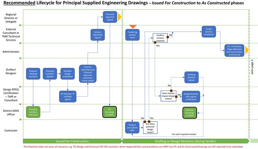
Figures 1.7(a) and 1.7(b) visually illustrate the recommended lifecycle workflow of a Principal Supplied
engineering drawing through the Issued For Construction phase to finalisation at the As Constructed
phase. The lifecycle details the RPEQ certification requirements for Issued For Construction (including
Design Revision versions); the lifecycle also details the drafter / designer verification requirements for
Drafting or Design Revisions and for the As Constructed version signoff.
1.5.1 Design changes
Design changes made after the scheme drawings have received financial approval, will require
engineering certification by an RPEQ in the revision area located in the bottom left-hand corner of the
title block, see Figure 1.6.3.1. This certification must ensure that the original design intent has not
been degraded, unless specifically approved otherwise by the client. The RPEQ is fully responsible for
the consequences of the design change. See Figures 1.7(a) and 1.7(b).
The process required to create the Design Revision drawings is described in Section 1.7.1.2.
1.5.2 Critical aspects of design
It is very important that all critical aspects of the design are explained to the construction contractor, to
avoid compromising the integrity of the design intent during construction. These requirements must be
highlighted in the drawings, project electronic model, and/or supplementary specifications and they
must be addressed at the pre-tendering and pre-construction meetings so that the contractor clearly
understands these issues and requirements. Typical examples of critical aspects of design are:
• on a multi-lane carriageway, the lane crossfall may be different in adjacent lanes, such details
must be clearly shown in the drawings, because varying the crossfall of road pavements to
manage road surface drainage, may cause potential aquaplaning issues
• product durability
• traffic performance
• safety, and
• functionality.
1.5.3 Design responsibilities and accountability
The overall responsibility for quality of the project design and documentation, lies with the organisation
carrying out the design. This responsibility is identified in the submission statement
'Scheme Submitted' on the first drawing of any set of project drawings.
Drafting and Design Presentation Standards Manual, Transport and Main Roads, April 2021 5Volume 1: Chapter 1 - Introduction However, the relevant RPEQ remains responsible for the overall provision of engineering services in terms of compliance with the Professional Engineers Act 2002 (Qld). Refer to Appendix 1A for legal obligations for designers, RPEQ engineering certification responsibilities and Safety in Design requirements. 1.5.4 Project electronic models and engineering drawings The department is moving towards a mandatory adoption of Building Information Modelling (BIM) progressively into all major state infrastructure projects by 2023. For the department, BIM is the process of digitally creating and managing asset / infrastructure data during its lifecycle. BIM processes use a federated model which consists of an assembly of individual discipline electronic models (such as 3D survey, design and As Constructed models with object-based attributed information) for design, construction, operations and asset management functions. A single federated model is useful for design co-ordination, clash detection and avoidance, approvals processes, design development, estimating and so on. The attributed project electronic models are becoming a standard method to check the design, together with its interfaces with the site and various design elements and between design disciplines, for example, civil, structural, electrical and so on. Once the design has been checked via the project electronic model, the projects engineering drawings can then be produced directly from this model. This process is designed to achieve a good engineering output, avoiding errors in the project electronic model and engineering drawings. Visualisations can also be produced from electronic models, to assist tendering and constructors to identify what they have to build. The Guideline for TMR Building Information Modelling (BIM) provides an overview of the department's plan for implementing BIM processes and methodology in delivering road infrastructure projects. This Guideline and other departmental BIM Design Manuals can be found under the department's Technical Publications website. 1.6 Departmental requirements 1.6.1 Use of consultant's logo The consultant responsible for preparing the engineering drawings, shall include their logo on each drawing, provided the logo does not occupy an area on the drawing greater than that occupied by the Queensland Government logo. In addition, where the consultant decides to include their logo on the drawing, then it must be inserted in the top right-hand corner of the drawing sheet as shown on Figure 1.6.3.1. 1.6.2 Signatures and names on scheme drawings Signatures on scheme drawings play a critical role in the legitimisation of scheme documents and the authorisation for the scheme to progress through the various process steps. Drafting and Design Presentation Standards Manual, Transport and Main Roads, April 2021 6
Volume 1: Chapter 1 - Introduction

Signatures are required for the following purposes:

    •     Engineering certification of the concept design and design development, for tender and during
          construction including its presentation on drawings for each area of engineering concerned. It
          also verifies all names and signatures on the drawings relating to engineering matters. This
          certification also includes the appropriate application of relevant departmental standards,
          specifications and project supplementary specifications.

    •     Where a design amendment has been approved after financial approval has been made, then
          the same certification requirements apply to that design change.

The use of electronic signatures on all engineering drawings is the department's default position
unless otherwise approved by the department on a project-by-project basis.

Electronic signature, in this context, translates to signing engineering drawings electronically in the
form of text, to certify the design represented by the drawing.

Increasingly, reliance upon hard copy drawings is diminishing as digital drawings, or electronic design
models become commonplace. It is now possible for drawings to be digitally developed, amended,
and approved with no requirements for hard copy and therefore, no necessity for 'wet ink' signatures.

Using electronic signatures effectively replaces existing wet ink signature requirements on engineering
drawings when submitted to the department and will be deemed equivalent to a wet ink signature,
provided it meets the criteria stipulated. In the event that electronic signatures are not possible and
wet signatures are provided, they are to be in blue or black ink.

While there is no direct legal or regulatory requirement explicitly portraying the use of signatures on
engineering drawings or models, common law contemplates that signatures and certifications
(including an RPEQ) may be in an electronic format.

Therefore, the department is satisfied that a ‘signature’ also encompasses an electronic signature and
that engineering drawings may therefore be electronically signed.

An electronic signature on an engineering drawing submitted to the department will:

    •     where required for RPEQ certification purposes, include the signatory's full name to represent
          their signature, RPEQ number, area of engineering and date

    •     where RPEQ certification is not required, then the signatory's full name, position title and date
          will suffice

    •     be located in the designated spaces on the drawings.

An example of an accepted electronic signature format is the full name, area of engineering,
RPEQ number and date (John Smith, Civil, RPEQ #12345, 01/01/2020), located in the allocated area
within the title block of a drawing.

1.6.2.1    Signatures of an overall nature

Signatures are required to cover the entire scheme drawings and are included on the first sheet of the
drawing set, under a listing of all the drawings appropriately identified (including document version and
date). Refer to Figure 1.6.2.3 for the signature box requirements, which includes approvals for:

    •     Scheme Submitted, and

    •     Scheme Scope and Financial Approval.

Drafting and Design Presentation Standards Manual, Transport and Main Roads, April 2021                   7
Volume 1: Chapter 1 - Introduction
Where the scheme drawings listing requires more than one sheet, the statement will appear only on
the first sheet of the drawing listing.
1.6.2.2 Scheme Submitted to the client
The person duly authorised by the service provider (engineering consultant or internal business unit),
shall formally (under a covering letter – see below) submit the contract materials (scheme documents)
to the client.
The meaning of ‘Scheme Submitted’ is:
• the scheme satisfies the requirements of the client's brief / functional specification
• the client has been progressively involved in the evolution of the design, including peer review,
and
• the engineering design has been certified by the relevant RPEQ(s), and that all signatures in
the drawing title block are authentic.
Scheme submission is a commercial response to a brief. The submission is by a single signature
under a listing of all scheme drawings on the first drawing of the drawing set. The organisation or
internal business unit's approving officer must sign under the words ‘Scheme Submitted’ and indicate
their organisation.
In addition, the submission covering letter shall state that the scheme has been prepared in
accordance with the (name of organisation) fully certified quality system and other relevant
organisational standard process and practices, and departmental technical requirements published in
various departmental documents, including manuals.
1.6.2.3 Scheme scope and financial approval
The Regional Director (or delegate) shall approve a scheme for tendering purposes. Approved means
the relevant Regional Director (or delegate) is satisfied that:
• The scheme satisfies departmental priorities in relation to:
- Investment Strategies
- Functional Road Hierarchy
- Traffic Operation Function
- Corridor Development Plans, and
- the need to be satisfied by the project.
• The scheme satisfies the requirements of the Queensland Transport and Roads Investment
Program (QTRIP) in terms of:
- Prioritisation
- Scope, and
- Cost.
• The appropriate level and extent of external communication has been undertaken.
Drafting and Design Presentation Standards Manual, Transport and Main Roads, April 2021 8Volume 1: Chapter 1 - Introduction
Scheme scope and financial approval is by a single electronic signature under a listing of all scheme
drawings on the first drawing of the drawing set. An email confirmation of the scheme scope and
financial approval from the Regional Director, or delegated signatory, will be sufficient evidence for the
design team to place the electronic signature into the statement box.
The required scheme submitted, scheme scope and financial approval statements, are to be included
on the front sheet of a project set of scheme drawings in accordance with the details shown in
Figure 1.6.2.3.
The 'scheme submitted, scheme scope and financial approval statement' can be inserted as a block
from the TMR AutoCAD Customisation.
The full names / signatures, position titles and dates on the 'scheme submitted, scheme scope and
financial approval statement' on the Issued For Construction drawing are to be provided in
AutoCAD text on all drawings submitted to Plan Room, including the As Constructed drawing.
Alternatively, these electronic signatures can be typed in black text directly in the PDF (refer
Section 1.7.1.5.2 for acceptable PDF format) by the signatory with their full name, position title, date
and organisation (if external), using a similar text style and size as the text used in the statement text.
Also refer Sections 1.7.1.2 and 1.7.1.3 for further details on the production of Revision and
As Constructed drawings.
Figure 1.6.2.3 – Scheme scope and approval statement
1.6.3 Other names on drawings and responsibilities
Names, signatures, RPEQ numbers, position titles and dates on engineering drawings play a very
important role in the legitimisation of scheme documents.
In this context, each engineering drawing must include the full name, relevant detail (RPEQ number,
or position title – refer to Section 1.7.1.4) and date in black text for an acceptable electronic signature,
as relevant of the person responsible for:
• producing the engineering drawing
• carrying out the design considering all areas of engineering, and
• certifying the design for each area of engineering, as relevant.
Drafting and Design Presentation Standards Manual, Transport and Main Roads, April 2021 9Volume 1: Chapter 1 - Introduction
1.6.3.1 Names and signatures in the title block
Every drawing must have a standard departmental title block that requires a range of information,
including names and signatures to be applied in order to complete the drawing.
Names, dates and details in AutoCAD text are required for Engineering Certification by an RPEQ.
Engineering Certification signatures are to be completed to facilitate identification of original drawings.
Drawings are to include the signatory's full name, engineering area, RPEQ number and date to satisfy
the department's responsibilities in accordance with the Public Records Act 2002 (Qld) and the
Evidence Act 1977 (Qld). In the unlikely event that an RPEQ is not required as a signatory on a
Revision drawing (refer to Section 1.7.1.4), the non-RPEQ signatory who is verifying the drawing shall
include their position title in lieu of an RPEQ number.
All names, RPEQ numbers, position titles and dates in the title block are to be in AutoCAD text.
The names, signatures and dates on previous revision drawings are to be transcribed in AutoCAD text
on subsequent Revision drawings and As Constructed drawings. Refer Sections 1.7.1.2 and 1.7.1.3.
The standard title block for the department's produced project drawings is shown in Figure 1.6.3.1.
1.6.3.2 Drawn
For drafters, it is expected that reasonable skill, care and diligence has been exercised by the external
consultant or internal business unit, in preparing the engineering drawings in accordance with the
ethics of the engineering profession and the department's drafting and design presentation standards,
which includes:
• the process of structuring the layout of the drawing (drafting and readability)
• the intent of the design is absolutely clear
• the accuracy of the design detail included in the drawing, and
• the appropriateness of the drawing to the users performing the next step in the process,
for example, approval, tendering and construction.
1.6.3.3 Designed
For designers, it is expected that reasonable skill, care and diligence has been exercised by the
external consultant or internal business unit, in carrying out the design in accordance with the ethics of
the engineering profession and the department's suite of road design standards, manuals, guidelines
and policies, which includes:
• the appropriateness of the designed components for their intended function
• the design complies with the relevant standards, guides, legislation and codes
• the design has been carried out in accordance with an approved quality system for
appropriateness of design inputs, including assumptions, and
• the appropriateness and accuracy of the design calculations.
Depending on the definition and complexity of the design, individuals performing these tasks would be
expected to have attained a two- or three-year civil engineering qualification, from a recognised
tertiary institution, as a minimum qualification.
It would be expected the designers producing the design, have been directly supervised by an RPEQ
in accordance with the Professional Engineers Act 2002 (Qld).
Drafting and Design Presentation Standards Manual, Transport and Main Roads, April 2021 10Volume 1: Chapter 1 - Introduction Figure 1.6.3.1 – Standard title block signature requirements Drafting and Design Presentation Standards Manual, Transport and Main Roads, April 2021 11
Volume 1: Chapter 1 - Introduction

1.6.3.4     Design certification

The department requires engineering drawings to be certified by an RPEQ.

Where a design drawing contains different areas of engineering, the design responsibility is identified
by separate engineering certification. Only an RPEQ, qualified in the area, may certify that relevant
part of the design drawing.

For Issued For Construction (Revision A) drawings (refer to Section 1.7.1.1), the certifying RPEQ must
insert their area of engineering, full name, RPEQ number and date in AutoCAD text, under the
'Engineering Certification (RPEQ)' area in the title block for each drawing.

Drawings with revised design content after being issued for construction, must record any engineering
changes to the design detail, intent and functionality (refer to Section 1.7.1.2). These changes must be
certified by the relevant RPEQ(s) in the revision area of the drawing sheet's title block, by writing their
full name, area of engineering, RPEQ number and date in AutoCAD text in the designated spaces
(refer to Figure 1.6.3.1).

1.6.3.5     Integrity of certification

The department depends upon the integrity of all engineering drawings produced for its infrastructure.
Therefore, the requirement to securely track and retain the certification process, related to a drawing,
is still valid.

The department will accept electronic signatures, but it is the signatory's responsibility (and the
signatory's organisation to which they belong) to embed and use a secure process in the production of
engineering drawings, to ensure fraudulent activity is avoided at time of certification, particularly when
inserting electronic signatures.

In the event that validity of information received is challenged during the life of the drawing, the
signatory (and the organisation to which they belong) is accountable and will be called upon to provide
traceability of the issued information.

Under the Electronic Transactions (Queensland) Act 2001, production of a document by electronic
communication requires a chain of evidence by:

     •    consenting to the production, by an electronic communication, of an electronic form of the
          document

     •    recording the transaction in its original form (originator, date / time sent and received), and

     •    providing a reliable way of maintaining the integrity of the information contained in the
          document.

It is the responsibility of both the sender and the receiver for the recording and retention of the
transaction information, as well as the documents being transacted.

Electronically signed engineering drawings will be accepted by the department in a Portable
Document Format (PDF) via electronic transaction. Examples of the format of these transactions may
include the following, in combination with a document transmittal:

     •    email attachments, or

     •    document management systems such as SharePoint, TeamBinder and so on, or

     •    various forms of cloud drives, such as Dropbox, OneDrive and so on.

Drafting and Design Presentation Standards Manual, Transport and Main Roads, April 2021                     12
Volume 1: Chapter 1 - Introduction
1.7 Management of project drawings
As part of all transport infrastructure projects undertaken on behalf of the department, design
documentation, including drawings, are to be prepared and submitted to the department to provide a
record of works between being Issued For Construction to As Constructed (Finalisation).
The department's Plan Room has a process to register drawings and request the department's
drawing numbers when drawings are ready for submission (Issued For Construction to
As Constructed). Please contact your local district's Plan Room representative for further information.
If there are changes to any drawings that have already been allocated the departmental numbers, the
department's Plan Room must be notified for accurate capturing of drawing information.
The need for capture, storage and retention of information is driven by statutory requirements, it is the
department's responsibility (the custodian), to ensure that the integrity of the received documentation
is retained using records management processes that are in accordance with:
• Public Records Act 2002 (Qld)
• Electronic Transactions (Queensland) Act 2001
• Queensland Disposal Authority Number 474 (QDAN 474), which sets out the retention period
of service function records, such as drawings, and
• various internal policies:
- the department's Records Management Policy
- Electronic Signature Policy for Engineering Drawings
- Digitisation and Disposal Policy
- Digital Recordings and Images Policy, and
- Information Asset Custodianship Policy.
Each of these statutes and policies support different objectives. To satisfy these requirements, all
engineering drawings are required to be captured using records management procedures as part of
the construction drawing development process. All Issued For Construction, Drafting or Design
Revision, and As Constructed engineering drawing metadata and digital images are loaded to the
department's asset management application GIMS. Figures 1.7(a) and 1.7(b) show the recommended
Lifecycle for Principal Supplied Engineering Drawings, indicating when drawings should be certified,
amended, registered and by whom.
Drafting and Design Presentation Standards Manual, Transport and Main Roads, April 2021 13Volume 1: Chapter 1 - Introduction Figure 1.7(a) – Principal Supplied Engineering Drawings – Lifecycle Part 1 Drafting and Design Presentation Standards Manual, Transport and Main Roads, April 2021 14
Volume 1: Chapter 1 - Introduction

Figure 1.7(b) – Principal Supplied Engineering Drawings – Lifecycle Part 2

Drafting and Design Presentation Standards Manual, Transport and Main Roads, April 2021   15
Volume 1: Chapter 1 - Introduction

1.7.1      Construction Drawings development process

Project drawings will often require a number of versions to accurately document the construction of
transport infrastructure projects.

For version of drawings at pre-construction phases (that is, concept, planning, preliminary and detailed
design), the department recommends using a numerical revision identifier to document the version of
each drawing, the initial version is to be labelled ‘1’ and any subsequent revisions are to be continued
progressively in numerical order (that is, ‘2’, ‘3’, ‘4’, ‘5’ and so on).

Once issued for construction, the department uses an alphabetical revision identifier to document the
version of each drawing, the initial version is to be labelled ‘A’ and any subsequent revisions are to be
continued progressively in alphabetical order (that is, ‘B’, ‘C’, ‘D’, ‘E’ and so on). These versions
include:

    •      Issued For Construction (mandatory – Revision A).

    •      Drafting or Design Revision (subsequent alphabetical revisions, as required during
           construction).

    •      As Constructed (mandatory – final subsequent alphabetical revision).

These versions of the project drawings and the procedure for their creation are explained in the
following sections of this manual.

1.7.1.1     Issued For Construction drawings

Issued For Construction is the term given to the first project drawings officially approved and produced
as a complete set of detailed design drawings ready to be constructed and which are released for
inclusion in the scheme. These drawings are the ‘A’ revision drawings initially issued for construction.
These drawings must have all appropriate signatures for engineering certification (RPEQ), scheme
scope and financial approval. These signatures are required prior to the drawings being placed in the
documentation for project construction (refer to Section 1.6.3.4 for RPEQ certification requirements).

1.7.1.2     Drafting or Design Revision drawings

Drafting or Design Revision is the term used when a project drawing has drafting, or design content
amended, after it has been issued for construction and during construction. Each area in the drawing,
where the drafting or design content has been amended, must be shown with a revision cloud around
the amendments and be labelled with the current alphabetical revision identifier, inside a triangle,
positioned next to the revision clouds. The revision area and revision identifier located in the title
block, are required to be updated to reflect the current revision of the drawing, as shown in
Figure 1.6.3.1. Where subsequent drafting or design revisions are required, the revision clouds from
the previous revision are to be removed. For certification or verification requirements of
Drafting or Design Revision drawings refer to Section 1.7.1.4.

1.7.1.3     As Constructed drawings

The term As Constructed is acknowledged within industry as a method to record the final construction
of a transport infrastructure project. As Constructed drawings are those drawings that record what was
physically constructed and therefore are a factual representation of the asset. They represent and
incorporate progressive design revisions certified by an RPEQ and drafting revisions in accordance
with the design dimensions, specifications and all other construction details and design variations.

Drafting and Design Presentation Standards Manual, Transport and Main Roads, April 2021                    16
Volume 1: Chapter 1 - Introduction For verification requirements of As Constructed drawings, refer to Section 1.7.1.4. A signed statement is required on each drawing, prior to being submitted to designers or drafters to update the drawing in AutoCAD, stating that 'the Works shown on the drawing are a factual representation of works constructed'. The signatory of this statement shall be the Contractor’s Construction Representative. For further details on conformance, responsibilities and specific requirements of As Constructed drawings for various delivery methods and contract types, refer to specification MRTS50 Specific Quality System Requirements. Designers or drafters are required to create As Constructed revisions in AutoCAD. Revision clouds shall not be shown on As Constructed drawings, as any previous amendment should already be accounted for in previous revisions of the drawing. The Drawing Index must also be updated to reflect the As Constructed drawing revisions. The revision area and alphabetical revision identifier, located in the title block, are required to be updated to reflect and verify that the drawings are the As Constructed version of the drawing. This update does not certify or confirm what has been constructed. Any required certification will have been undertaken in previous revisions as described in Section 1.7.1.4 and the Contractor's factual representation signatory will have, in effect, verified this by confirming the constructed representation. Figure 1.6.3.1 shows an acceptable As Constructed drawing statement (that is, factual representation of the works constructed statement). When updating the drawings to the AutoCAD As Constructed versions, the factual representation statement and signature by the Contractor’s Construction Representative, are to be electronically transcribed. It is then expected that As Constructed drawings, produced as a factual representation, require no further revision and are therefore subsequently saved to a PDF, produced from AutoCAD. These files are to be submitted to the department via electronic transaction for registration by Plan Room, refer to Section 1.7.1.5 for specific requirements when submitting drawings for registration. The final payment certificate certifies that the road infrastructure has been built in accordance with project drawings and specifications. It is not intended for As Constructed drawings to be represented by detailed site survey measurements, except for changes to new or relocated underground services, drainage, foundations and other subsurface infrastructure which must be established before backfilling occurs (or for piles as driving or drilling is completed). As Constructed drawings are a separate deliverable item from the 'As Constructed Survey’. 1.7.1.4 Drawing certification and verification on Revision drawings Certification, where RPEQ sign off is required in the revision area located in the title block when amendments have been made to the ‘Issued For Construction’ version of the project drawings. Where the amendment would affect the engineering intent or functionality, the Design Revision shall be certified by the relevant RPEQ design engineer/s. Where the principal has supplied the Issued For Construction drawings, this will typically be the Principal’s RPEQ design engineer, or the Contractor’s RPEQ design engineer. The Design Revision drawing must be certified by an appropriate RPEQ with their full name, area of engineering, RPEQ number and date (John Smith, Civil, RPEQ #12345, 01/01/20) in AutoCAD black text and reissued with the next sequential alphabetical revision identifier, see example in Figure 1.6.3.1. Drafting and Design Presentation Standards Manual, Transport and Main Roads, April 2021 17
Volume 1: Chapter 1 - Introduction

It is expected the certification of an As Constructed drawing, following an Issued For Construction, or
Drafting or Design Revision drawing, is not required as this final revision only involves design or
drafting verification acknowledging that previous certified revisions have been incorporated into the
As Constructed version.

Verification sign off in the revision area located in the title block is required where amendments have
been made to the Issued For Construction version of the project drawings and the changes do not
affect the engineering intent or functionality. Such drawings are not required to be certified by an
RPEQ, but are to be verified by the appropriate person (for example, draftsperson, designer or RPEQ)
with their full name, position title and date (Mary Jayne, Civil Designer, 01/01/20) in AutoCAD black
text, see example in Figure 1.6.3.1.

Examples of where verification (non-RPEQ) is sufficient include:

    •     issuing a Drafting Revision drawing, due to a service being located in a different position

    •     issuing an As Constructed drawing, which is the final revision following a
          Drafting or Design Revision drawing. This only involves the removal of revision clouds and
          does not certify or confirm what has been constructed, see Figure 1.6.3.1 for typical elements
          depicted on the title block.

1.7.1.5     Submission of drawings for registration

As a public record, the expectation is that presentation of detailed design drawings complies with the
department's Drafting and Design Presentation Standards Manual (Volume 1 and Volume 2). Bridges
and other structures drawings are to be presented in accordance with
Volume 3: Structural Drafting Standards.

It is mandatory that all versions of drawings produced for construction purposes, including
As Constructed drawings must:

    •     be allocated a departmental drawing number

    •     comply with presentation standards described in the department's Drafting and Design
          Presentation Standards Manual, and

    •     be submitted for digitising and registration by the department.

Drawings other than engineering drawings depicting project information that informs the final design,
for example, Geotechnical Investigations, Resumptions, Native Title and so on that require registered
departmental drawing numbers, also need to be submitted to the department's Plan Room.

Planning drawings, or those drawings prepared during project development prior to
Issued For Construction, are not required to be submitted for public record to the department's
Plan Room. It is expected that Regional / District offices and contractors, engaged in the production of
such drawings, will maintain their own system for identification and records management of these
drawings.

Detailed As Constructed design drawings, including the drawing containing the updated
'Drawing Index', are required to be submitted by the Superintendent or the Principal’s Construction
Administrator to the department's Plan Room for digitisation and registration.

The Superintendent or the Principal’s Construction Administrator is also responsible to supply a copy
of the complete set of As Constructed drawings to the corresponding Regional ARMIS Section of the
department for updating of the ARMIS database.

Drafting and Design Presentation Standards Manual, Transport and Main Roads, April 2021                   18
You can also read