Dragons - a unique fusion of art and engineering - Ernst & Sohn
←
→
Page content transcription
If your browser does not render page correctly, please read the page content below

Jindřich Beran, Jan Štolc

Dragons – a unique fusion of art and engineering

1        Introduction                                           ments would be suspended and one with a supporting
                                                                shell. Neither of these variants met the two primary
Excon worked together with the Czech glass company              conditions for assembly and maintenance: clearance
Lasvit to create an impressive work for the Imperial Pa-        within the structure (including the placement of inter-
cific Hotel on the Northern Mariana Island of Saipan.           nal switchboards) and the ability to replace individual
This monumental light fixture and giant illuminated jewel       scales. Therefore, a third variant was selected. The load-
took three years to bring to fruition, resulting in two metal   bearing element of each supporting structure comprises
and glass dragons, each weighing twenty tons, that are the      a hollow space truss structure made of circular rings
focus of visitors’ attention as they enter the hotel lobby.     with tubular cross bracing, which simultaneously forms
Individually the dragons are each a magnificent gem, and        the overall shape and line of the body, 32 m long with a
together they form a single impressive piece of jewelry.        contour height of 13 m. The two dragons are nearly mir-
                                                                ror images: the only minor differences are in the posi-
Each dragon’s body is sheathed with 13,000 crystal scales,      tioning of the suspension points resulting from the lay-
and each scale is encrusted with nearly two hundred indi-       out of the supporting ceiling structure above.
vidually attached Swarovski crystals. Stretched out fully,
each dragon would reach a length of 50 meters. Its eye          The final version of the project resulted from long hours
alone is an impressive 220 × 90 cm.                             of fine-tuning the shape of the supporting trusses that
                                                                created the necessary support for the back-lit glass
The crystals not only reflect light, but are also illuminated   shell. Also important was selecting the proper structur-
by programmable LED modules that can be individually            al material for all cross-sections of the support elements
controlled by computer. The dragons can, for example,           that was readily available and sufficiently corrosionre-
“change their skin” from pink to green at the touch of a        sistant for the duration of transport and installation in
button. Preset effects are also available, including color      the aggressive coastal environment. Corrosionresistant
changes or even light waves.                                    steel 1.4404/316L, also known as surgical steel, was se-
                                                                lected.

2        Architectural and structural design                    The structure is suspended from eleven different lengths
                                                                of Macalloy SC460 stainless steel compact strand cable.
The aim of the project was to design, manufacture, and          The positions of the cables were determined by the size
assemble the supporting structure of each dragon, includ-       and weight requirements of the individual elements of
ing its suspension, connection points, wires for assem-         the structures, taking into consideration the spatial ri-
bling the scales, and elements for mounting other compo-        gidity of the overall structure. The cables are 16 mm in
nents of the sculpture.                                         diameter, except for the cable under the greatest load
                                                                (behind the dragon’s head), which is 19 mm in diame-
During the preparatory work on the dragons’ support             ter. All bars are fitted with tensioning elements and
structures, the designers rejected two variants: one uti-       strain gauges that monitor the forces introduced during
lizing a supporting spine on which the cladding ele-            assembly to facilitate assembly and adjustments.

Fig. 1   Basic idea of the structure

                                                                                           European Steel Design Award 20211
Fig. 2   Overall diagram of the truss support structure

Fig. 3   3D model – basic structure without additional components   Fig. 4   Detail of the head structure with attachment points for the installati-
                                                                             on of additional elements

In addition to the weight of the steel structure itself and         circular braces with a maximum diameter of 2.2 m, to which
the weight of the shell made of glazed scales, the support          the tubular elements of the space truss are connected.
structure also bears the weight of the additional compo-
nents (beard, claws, eyes, teeth, tongue, dorsal spines,            The weight of the circular braces is reduced by drilled
massive tail, etc.) that no dragon can be without. Another          holes, which are then conveniently used to direct the ca-
constant load is the electrical equipment: the junction             bling for the LED components. The subsupport elements
boxes, cables, connectors, light fittings, etc. The additional
weight of the people who must be present directly on the
structure during assembly and servicing was also taken
into consideration.

No part of the main structure repeats, as its shape is
curved vertically and horizontally, and the additional
components are also varied. Based on feedback from the
investor, designers modified the contours of the structure
multiple times throughout the design process to improve
the appearance of the mythical creature, which also af-
fected the support structure.

Thanks to the smooth collaboration with Lasvit’s design-
ers, we were all able to work entirely in the 3D models
with regular bidirectional updates, which allowed us to
work simultaneously on the static, structural, and artistic
aspects of the design.

The following images show the complex shape of the truss
support structure in more detail. It comprises transverse           Fig. 5   3D model – dragon leg

2        European Steel Design Award 2021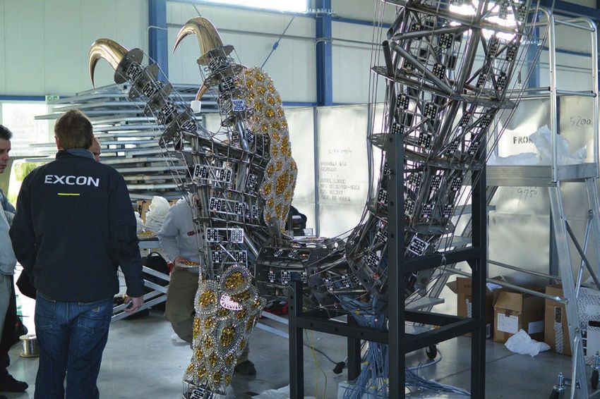
then protrude from the basic tubular truss to form the de-
sired shape or support an ornamental feature. The entire
structure is covered with a system of heavy-duty longitudi-
nal wires for attaching the scales, which, although not
foreseen in the static model, were nevertheless used as a
stabilizing element in the design of the transverse rings.

A separate chapter in the preparation of the static and
subsequently the structural model was the creation of the
shapes of the main external components of the dragon’s
body. These included supports for the tail, dorsal spines,
claws, eyes, tongue, teeth, and long flowing hairs on the
head section of the sculpture. These had to function stati-
cally, as well as take into consideration coverage with an
intricate layer of scales while still looking natural.         a)                                            b)

                                                               Fig. 6   Cardan hinge: a) 3D model; b) actual hinge during pre-assemblys
3     Dynamic calculation

The island of Saipan is part of the North Mariana Islands,
a Western Pacific archipelago located in a tectonically ac-    many obstacles due to the size of this non-standard struc-
tive area. The design, therefore, had to include an analysis   ture and some of the atypical details required, as seen in
that demonstrated sufficient structural safety even under      the images.
seismic loading. The original intent to attach the dragon by
thin, flexible horizontal rods with damping elements to the    The actual work on the structural model was also tailored
building structure was rejected for aesthetic reasons. The     to the production of the individual elements, as it was
final decision was to leave the dragon freely suspended,       necessary to accurately identify all the parts of the struc-
and the analysis focused mainly on determining the maxi-       ture not only by their number but also by their position
mum horizontal deflection during forced oscillation. Too       (right, left, top, bottom). The DSTV data was exported di-
much deflection would have compromised the function of         rectly from the structural model to machine production to
the tie rod connections. Eigenfrequencies (natural vibra-      minimize manually produced complex shaped parts (man-
tion frequencies) were determined on the global model,         ual production always poses some additional risk).
which became the basis for calculating the maximum hori-
zontal deflection (or maximum rod deflection angle).           A crucial detail of the structure was the locations of the
                                                               hinges, which were placed based on the results of the
A team at the Institute of Theoretical and Applied Me-         static and dynamic calculations. Universal joints (cardan
chanics in Prague then verified the result using a separate    hinges), i.e. a longitudinally rigid joint allowing articulated
simplified calculation. Here the structure was simplified      movement in both directions, were used. The central sec-
and modelled as a nonlinear pendulum with one degree of        tion of the hinge was milled from a single circular section
freedom. The pendulum was assumed to be kinematically          to avoid any defects and imperfections that might arise
excited by typical accelerograms corresponding to the ex-      from welding.
pected earthquakes to approximate the expected maxi-
mum response.                                                  For the production process, manufacturing and assembly
                                                               aids were prepared as part of the structural modelling, to-
Analysis of the system showed maximum lateral deflec-          gether with drawings and tables of the geodesic points of
tions of some elements that required modification of the       the individual assembly units and the overall structure.
design of specific structural details. Where the hinge an-     Unusual for this project was the documentation of the
chor detail rotation exceeded the manufacturer’s allowa-       production assembly of each unit. Due to the spatial com-
ble value, designers added lateral hinge elements between      plexity of the entire structure, it was practically impossible
the structure and the hinge to allow for such large deflec-    to position the assembly accurately using traditional di-
tions (s. Fig. 9).                                             mensioning. Therefore, the position of each of the trans-
                                                               verse rings was described by the local coordinates of the
Finally, the resulting static and dynamic design was veri-     centre and the main connection points in relation to a
fied and validated by an independent firm, Finley, who         preprepared 3D assembly grid.
certified the documentation for the US authorities.

                                                               5        Production and pre-assembly
4     Structural model
                                                               The construction parts were produced serially, primarily
The entire digital 3D structural model was created in          by machining. The prepared and machined parts were as-
Tekla Structures. The modelling process encountered            sembled into mounting units using the assembly documen-

                                                                                                    European Steel Design Award 20213
lation. This required finding a sufficiently sizeable empty
                                                                      hall with all the necessary facilities for assembly. For this
                                                                      purpose, the EXCON hall in Teplice, which had been con-
                                                                      veniently cleared to install new equipment, provided suffi-
                                                                      cient space.

                                                                      Preassembly was carried out in a similar manner as the
                                                                      planned assembly on Saipan. For the final assembly, it was
                                                                      also necessary to verify all the centres of gravity of the in-
                                                                      dividual assembly units and draw up a detailed assembly
                                                                      procedure. This was the only way to assemble the indi-
                                                                      vidual units on site using only the permanent mounts and
Fig. 7   Finished unit ready for pre-assembly                         assembly hoists (no cranes and other lifting mechanisms
                                                                      could be used) while maintaining the necessary precision
                                                                      at the connection points.
tation for each unit. First, each transverse ring was secured
in space according to its coordinates and then connected              Preassembly was carried out on both truss structures to
by partial welding of the primary support tubes to the pre-           check the overall shape, structural assumptions, and all
vious ring. This was followed by the fitting and securing of          necessary electrical, cladding, and individual component
the next ring, and so on. By consistently securing all the            connections. It was also essential to check all welds in
rings on the unit using a single coordinate system (and not           parallel. Structural components were then marked, disas-
in relation to the previous ring), we avoided the buildup of          sembled, and prepared for the overall passivation of the
possible minor errors and inaccuracies. After complete as-            corrosionresistant structure. The heaviest unit – the head –
sembly, each unit was aligned geometrically, and this meas-           weighed in at 840 kg, the body unit 725 kg and the heavi-
urement was checked against the 3D structural model.                  est leg 260 kg.
Once the correct shape was confirmed, the unit underwent
final welding and preparation for preassembly.                        As part of the pre-assembly, tests were conducted on the
                                                                      functional continuity of some parts of the glass cladding
Due to the atypical nature of the entire structure, a com-            and individual components and the internal LED lighting.
plete preassembly was carried out prior to the final instal-          Additionally, the conditions for the movement of the
                                                                      workers inside the truss structure were verified (e.g. to
                                                                      check that there was enough space for the assembler to
                                                                      move inside each part of the assembled structure).

                                                                      6      Assembly of the structure

                                                                      On-site installation took several months. Most parts were
                                                                      transported by ship, with air transport used for some (pri-
                                                                      marily smaller) parts.

                                                                      As the assembly site was quite far away, all necessary tools
                                                                      needed to be prepared. In addition, coordination of the
Fig. 8   View of the assembled truss structure                        structure’s anchor points was essential during the con-
                                                                      struction of the whole building. The first thing that was
                                                                      checked prior to final assembly was the readiness of these
                                                                      points to avoid collapse or damage to the structure. All
                                                                      fabricated components were also rechecked for damage in
                                                                      transit before actual assembly started.

                                                                      The entrance hall where the assembly was to take place
                                                                      was already complete, so great care had to be taken to
                                                                      avoid damage to finished surfaces. First, the first truss
                                                                      structure was assembled and handed over for subsequent
                                                                      mounting of the electronics and cladding elements. Only
                                                                      after the first truss structure was successfully completed
                                                                      was the assembly of the second truss structure begun. An
                                                                      interesting and necessary part of the assembly was adjust-
                                                                      ing the forces in the metal cable hangers as measured by
                                                                      strain gauges to ensure that the reactions introduced by
Fig. 9   View of the structure, cladding and components of one unit   the cables into the structure corresponded to the designed

4        European Steel Design Award 2021
Fig. 10 View of the completed sculpture

values. The strain gauge measurements were carried out at     Authors
each assembly stage to verify that the results conformed to   Ing. Jindřich Beran (corresponding author)
                                                              beran@excon.cz
the design.
                                                              Ing. Jan Štolc, CSc.
The technicians were able to move around inside the           stolc@excon.cz
sculpture during the assembly of the support structure and
                                                              EXCON, a.s.
the subsequent installation of the shell and internal elec-
                                                              Sokolovska 187/203
trical equipment. In total, some members of the team          190 00 Praha 9 – Vysočany , Czech Republic
spent up to two months on-site inside the steel monster.      www.excon.cz, www.excon.eu

                                                                                                   European Steel Design Award 20215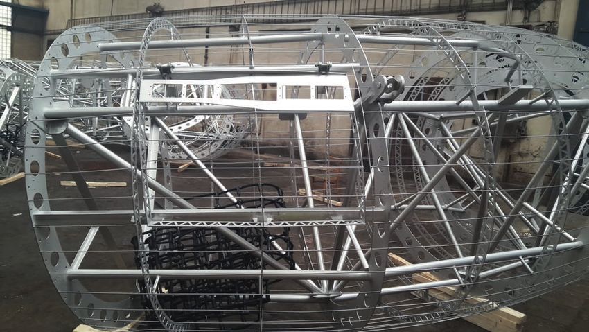


You can also read