Electric bicycle Manual - Pluto R Pluto C2 - RBSM Sports
←
→
Page content transcription
If your browser does not render page correctly, please read the page content below
RBSM
                                              Burlington, Ontario
                Toll free customer service line: 1 844 202-3572

Electric bicycle Manual

 Pluto R            Pluto C2

                                                                1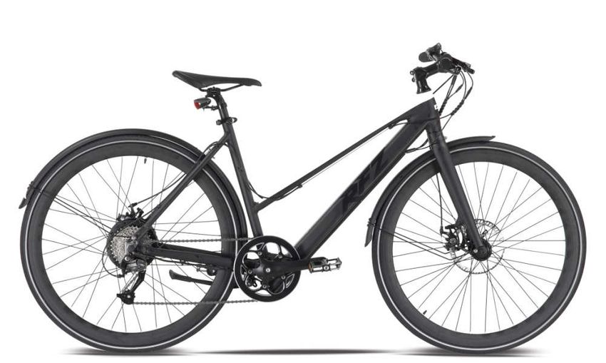
You must read this manual carefully to         The factory is constantly working on the            Used symbols

familiarize yourself with your vehicle. The    further development of all models. Please           Important notes for your safety are specially

expert treatment, in addition to the regular   understand that changes to the scope of             marked. Be sure to follow these instructions

care and maintenance of the vehicle serves     delivery in terms of shape, equipment and           to avoid personal injury and damage to the

to maintain its value.                         technology are therefore possible at any            unit:
                                               time. Therefore no claims can be derived            WARNING
                                               from the information, illustrations and             Warns of dangers to your health and
For reasons of safety, please also pay
                                               descriptions of these operating instructions.
attention   to    the    information   about                                                       indicates possible injury risks.

modifications, accessories and spare parts.
                                               All texts, illustrations and instructions of this
                                                                                                   DANGER
                                               manual are to be found on the information
Provide the owner's manual with the sale of                                                        Indicates a potential hazard to the device or
                                               stand at the time of printing. The information
your vehicle.                                                                                      other objects.
                                               contained in this manual is valid on the

                                               closing     date.   Errors    and    omissions
                                                                                                   NOTE
                                               excepted.
                                                                                                   Highlights tips and information for you.
                                               Reproduction, duplication or translation,

                                               even in part, is not permitted without

                                               permission. All rights under the copyright

                                               law are expressly reserved. Changes
                                               reserved.

                                                                                                                                               2
Content

Bicycle side view right …………………..4          Tire pressure ……………….……….…..24             Bicycle car / Care products…….....…. 31

Handlebar fittings …………………….…5              Riding ………………………….……24-25                  Disposal …………………………..…….32

Display ……..………..………………....6-15             Support lever...………………………….25              Tire Care……………………………...... 33

Seat position ………..………………….16               Range….……………………………….. 25                   Technical changes……………….…….33

Adjust saddle …………..………………17                Pushing assist………………………… 26                Maintenance and care ………..........34-36

Adjust the handlebars…………….….. 18           Brakes …………………………………..27                   Cranks, pedals …………………….….....37

Safety instructions for the charger …..19   Turn off the bicycle……………………. 27           Steering bearings, spokes……………...38

Charger functions………..……………. 20             Safety instructions……………………..29            Removing the battery……………..... 39-41

Safety information for the battery..…….21   Remove front wheel for transport….... 29   Technical data …………………..….. 42-43

Handling of the battery and charger…..22    Transport ……………………………..…29                 Vehicle Unpacking and Assembling 44-46

Charge the battery ……………………..23             Transport of loads ………………..……30

                                                                                                                             3
Right side view
                                                           2

1 saddle height quick release lever
                                                                   3
2 display                                 10
3 handlebar controls                           1
                                                                       4
4 frame number

5 Front disc brake

6 battery
                                      9
7 pedal

8 Rear derailleur
                                                       6
9 electric motor

10 Rear disc brake
                                                   7           5
                                          8

                                                                           4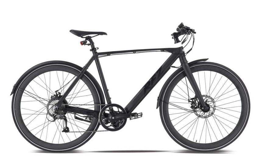
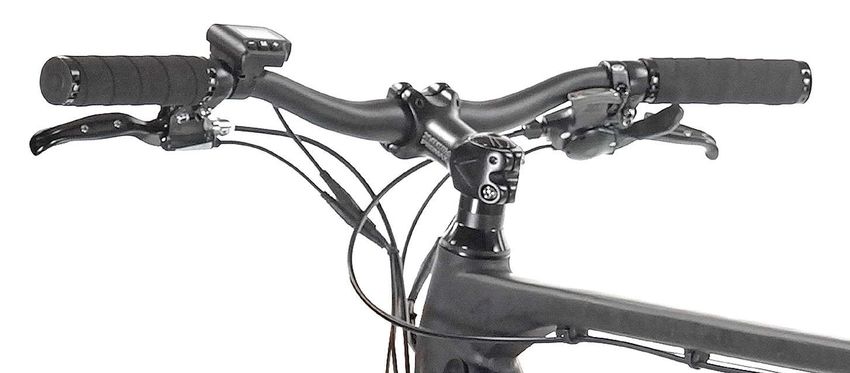
Function and operation of handlebar fittings
                   2                                                     4
                                   3

                                                               5     6
               1

                                               handlebar fitting right
handlebar fitting left
                                               4. right grip
1. front brake lever
                                               5. 9-speed shifter
2. left grip
                                               6. rear brake lever
3. display

                                                                             5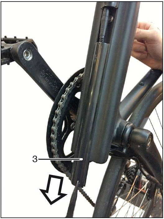
Display,Product name and model
Electric bicycle intelligent display; model: KD580.
Specifications
   ●24V/36V /48V Power Supply
   ●Rated current 10mA
   ●The maximum working current 30mA
   ●Off leakage current
Function Summary and Button Definition                                 Monitor Area Instruction
    ◆Function Summary
KD580 can provide a lot of functions to fit the users’ needs. The
indicating contents are as following:
    ●Battery charge-control indicator
    ●Assistance-level indication
    ●Speed indication (incl. running speed, max speed and average
speed)
    ●Motor-output indicator
    ●Trip time indication
    ●Trip distance and Total distance
    ●The push-assistance function
    ●The Lighting On/Off
                                                                       ◆Switching the eBike On/Off
    ●Error Code indication
                                                                       To switch on the eBike system, hold MODE button for 2 s.
    ●Various Parameters Settings (e.g., wheel size, speed
                                                      speed-limited,
                                                                       In the same way to hold MODE button for 2 s again, the eBike
battery level bar, PAS level, password enable, controller limited
                                                                       system will be switched off.
current etc .)
                                                                       When switching off the eBike system the leakage current is less
    ●Recover Default Settings
                                                                       than 1 uA.
                                                                       ■When
                                                                          When parking eBike for more than 10 minutes, the eBike system
    ◆Button Definition
                                                                       switches off automatically.
    There are three buttons (               ) on the KD580 display
that represented
                                                                       ◆Display Interface
by the following functions respectively: MODE, UP and DOWN.
                                                                       After switching on the eBike system, the display shows Running
                                                                       Speed. On the condition of riding, to change the indicated
                                                                       information, press MODE to show in turn as below: Running Speed
                                                                       (Km/h) → Trip Distance (Km) →Trip →      Time (Hour.) → Average
                                                                       Speed (Km/h) → Max Speed (Km/h). Each state will display for 6
                                                                       seconds and then automatically returns to the Running Speed
                                                                       interface. On the condition that the speed is 0 km/h, Trip Distance
                                                                       will be added to the circulation interface.
                                                                                                        interfac
                                                                                                                                          7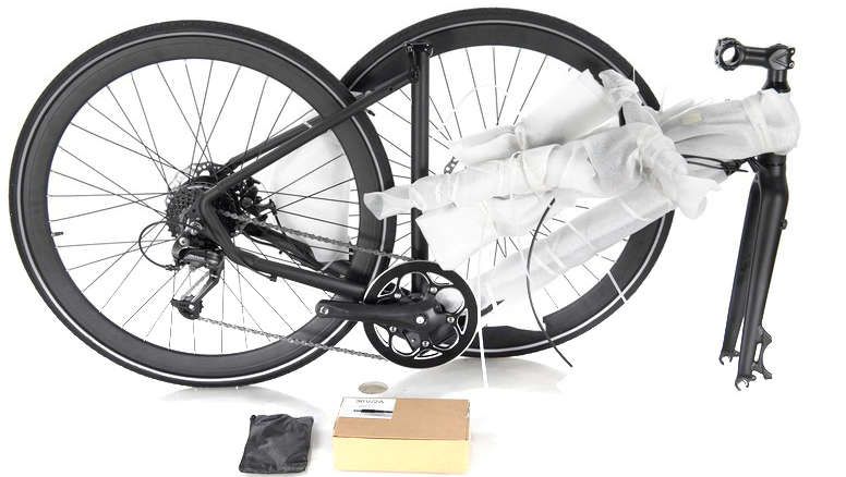
In the same way to hold UP button for 2 s again, the backlight   will
                                                                      be switched off.

                                                                      ◆ Assistance LevelSelection
                                                                      Assistance levels indicate the output power of the motor. The default
The circulation interface of the condition that the speed is 0 km/h   value is level
                                                                      “1”.
◆ Switching Push-assistance modeOn/Off                                The default power ranges from level “0” to level “9”.The output
   To access the push-assistance mode, hold DOWN always, the          power is zero on Level “0”. Level “1” is the minimum power. Level “9”
eBike will go on at a uniform speed of 6 Km/h, “P” is showed on the   is the maximum power.
screen at the same time. The push- assistance function switches off
as soon as you release DOWN.

                       Push-assistance Mode                                                   Assistance Level “4”
■ Push-assistance function may only be used when pushing the
eBike. Danger of injury when the wheels of the eBike do not have
ground contact while use the push-assistancefunction.

◆ Switching the LightingOn/Off
To switch on the display backlight , hold UP button for 2 s.

                                                                                                                                              8
◆ PowerIndicator
                                                                                           ◆ Trip DistanceClearance
The out power of the motor can be indicated   ■ Offer the display to a Service Center
                                                                                           Clear Trip means single trip distance
by the display.                               when an error codeappears.                   clearance.Press UP or DOWN button to
                                                                                           choose YES or NO to clear the trip distance.
                                              General Settings
                                                                                           The default is NO. If you choose YES and
                                                  After the eBike system is switched on,   press MODE button to confirm the option,
                                                                                           the display will show OK and return to the
                                              to access general settings menu, hold both   general selection settings
                                              UP and DOWN button for 2 s.                  interface.Otherwise the display will return to
                                                                                           the general selection

      Motor Power Indicator Interface

◆ Error codeIndication                            Press Up or DOWN button to select the    settings interface directly. Various symbol

If there are errors about the electronic      content, press MODE to confirm the           definitions refer to Attached list 3.

control system, the error code will appear    corresponding settings.

automatically. Here is the message of the

error code in Attached list 1.

                                                                                                      Trip distance clearance

            Error Code Indication

                                                                                                                                         9
◆ Unit Mi/KMConversion                       ◆ Wheel DiameterSettings                       ◆ Speed-limitSettings
   Set Unit represents unit settings.           Set WD represents wheel diameter               Set LS represents limit speed settings.
   To convert unit, press UP/DOWN to         settings. Electable values are 16, 18, 20,     When the running speed is faster than
increase or decrease until the desired                                                      limit speed, the eBike system will switch off
                                             22,24, 26, 700C and 28. Default diameter of
setting is displayed.                                                                       automatically. Limit speed range is 12Km/h
                                             Pluto R is 700C.
   To store a changed setting, press MODE                                                   to 40Km/h.Limit speed default value of Pluto
                                                To change basic settings, press
button to access trip distance clearance                                                    R is 32Km/h.
                                             UP/DOWN to increase or decrease until the
settings and the display will show OK then                                                     To change basic settings, press
                                             desired value is displayed.
returns to general selection settings                                                       UP/DOWN to increase or decrease until the
                                                To store a changed setting, press MODE
interface. The default unit is Metric.                                                      desired value is displayed.
                                             button   and the display will show OK   then
                                                                                               To store a changed setting, hold MODE
                                             returns to general selection                   for 2 s    and   the display will display OK
                                             settingsinterface.                             then returns to general selection
                                                                                            settingsinterface.

  Mile and Kilometer Conversion Settings
                   Interface

                                              Wheel Diameter Settings Interface

                                                                                                      Limit Speed Settings Interface
                                                                                                                                           10
◆ Battery Power barSettings Personalized Parameter Settings ◆ Power Assistant Level Settings
VOLrepresents voltage settings.Each Personalized Parameter Settings can Power Assistant Leveloption
barrery presents a voltage value.5 bars match various requirements in use. There In assistance level settings, there are 8
voltage values must be entered one by one. are 8 settings items, such as Power modes to select: 0-3, 1-3, 0-5, 1-5, 0-7,
For example, VOL 1 is the first bar voltage assistant level Settings, Slowly Start up 1-7,0-9 , 1-9. The default mode is0-5.
value, the default value is31.5V. Settings, Power- on Password Settings and To select the mode of assistance level,
To set battery power bar, press Exit settings. press UP/DOWN to increase or decrease
UP/DOWN to increase or decrease the Hold UP and DOWN button more than 2 until the desired setting is displayed.
number. seconds to enter general settings, then use To store the changed setting and access
To store a changed setting and access the same manner to enter personalized the PAS ratio settings page, press MODE
the second bar, press MODE button. parameter settings selection interface. button.
By analogy, after 5 bars voltage values Press UP or DOWN button to choose the
is entered, hold MODE to confirm and return personalized parameter settings items, then
to the previous menu. press MODE button to enter the
corresponding settings interface.
PAS Mode option Interface
Battery Power Bar Settings Personalized parameter settings Interface
11PAS Ratio settings ◆ Slowly Start upSettings ◆ Power-on Password Settings
To modify the value of PAS ratio can Slow Start represents slowly start up. P2:0000 represents power-on password
match the different requirements. The range is 1-4, 4 is the slowest. settings. The default power-on password is
For example, the range is “45-55 To change slowly start-up settings,press 1212.
percent” of 1 level, bottom value can be UP or DOWN button to select,press MODE To access the power-on password
modified and the default is 50 percent. button to confirm and the meter will display settings, press UP/DOWN to modify the
Press UP or DOWN button to increase OK then return to general selection settings value and then press MODE to confirm digit
or decrease the number. Press MODE interface. The default value is1. one by one until the correct 4-digit password
button to confirm and turn to the next PAS is completed, and then press MODE to
ratio settings. 9 levels is the maximum. After access power-on password enable settings
all PAS ratio inputted, press MODE button interface, otherwise stay on the password
to confirm and return to general selection inputstate.
settings interface. Various symbol
definitions please refer to Attached list 2. Interface of slowly settings up
Power-on Password Entering Interface
PAS Ratio Interface
12Power-on Password Enable/Disable Power-on Password Modify ◆ Exitsettings
Press MODE button to enter power-on When the display shows “Password Set, In the settings state, press MODE button
password modify interface. Press UP or P3”, press UP/DOWN to modify the value to confirm the input. Hold MODE button
DOWN button to select Disable or Enable and then press MODE to confirm digit one more than 2 seconds to save the settings
and press MODE button to confirm. by one until the new 4-digit password is and then exit the current settings. Hold
Power-on Password default is Enable. If completed. DOWN button more than 2 seconds to
you choose Enable, press MODE button to To store the new power-on password, cancel the operating but not saving the
enter Power-on Password Modify interface, hold MODE button for 2 s and then exit settings data, and then return to
otherwise exit the power-on password settings. previousmenu.
settings interface.Default power-on When switching the eBike system on ■ If there is not any operations in one
password value is1212. next time, the display will show P1,0000, minute, display will exit the settings state
please input the new password to power on. automatically.
Power-on Password Disable/Enable Power-on Password Modify Interface
Interface
13Recover default settings Quality assurance and warranty 6) The fault or damage is caused by the
dEF means recover default settings. scope force majure (such as fire, earthquake, etc,)
Press both UP and MODE button more than 1. Warranty or natural disasters like lighting,etc.
2 seconds to enter recover default settings. 1). The warranty will be valid only for
Press UP or DOWN button to choose Y or N. products used in normal usage Connection layout
Y means that recovers default settings. N andconditions. Connector line sequence
means that do not recover default settings. 2).The warranty is valid for 24 months
When after the shipment or delivery to the
it is Y, hold MODE button more than 2 customer.
seconds to recover default settings, the 2.Others
display showsd EF-00 at the same time,and The following items do not belong to our Display-sideConnector
then return to general display state.The warranty scope. Display-sideadapter
default state is No. 1) Shell is broken when display is out Switch wiring
of thefactory.
2) Wire isbroken.
3) It cannot bedemolished.
4) The damage is caused by wrong
Recover Default Settings Interface installation oroperation.
5) Beyond the warrantytime.
14Line sequence table Attached list 1: Error code definition
Line sequence Color Function Error Code Definition
21 Current Abnormality
1 Red(VCC) +
22 Throttle Abnormality
2 Blue(K) Lock 23 Motor Abnormality
24 Motor Hall Abnormality
3 Black(GND) -
25 Brake Abnormality
4 Green(RX) RX 30 Communication Abnormality
5 Yellow(TX) TX
Attached list 2:Power assist table
■
Somewireusethewater-proofconnector,usersarenotabletoseethe Level 1 2 3 4 5 6 7 8 9
inside color. Level
Operation Cautions Item
Be care of the safety use. Don’t attempt to release the connector 0-3/1-3 50% 74% 92% — — — — — —
when battery is on power. 0-5/ 1-5 50% 61% 73% 85% 96% — — — —
◆ Try to avoidhitting. 0-7/ 1-7 40% 50% 60% 70% 80% 90% 96% — —
◆ Do not modify system parameters to avoid 0-9/ 1-9 25% 34% 43% 52% 61% 70% 79% 88% 96%
parametersdisorder.
◆ Make the display repaired when error codeappears.
15Seat position
In order to allow comfortable, fatigue-free The handlebar height is correct when the
and safe driving, the saddle and handlebar handlebar stem (2) with the upper edge of
height must be adapted to the body size. the saddle (3) is level or slightly higher.
The saddle height is correct when sitting
with the leg not fully extended (1), the foot
rests on the pedal in the lowest position.
The tiptoes must still touch the ground.
16Adjust saddle height Adjust saddle
- Release the quick-release lever (1),
determine the seat height and tighten the
lock.
- By adjusting the nut (2) on the quick
release lever, the clamping force can be
regulated.
The quick release lever (1) must be with
close noticeable backpressure.
WARNING
The saddle can also be tilted and
A not completely closed quick-release lever
adjusted in the longitudinal direction.
can open again. This can cause the saddle
- Loosen the screw (1).
to move down while driving. This can lead to
- Place the saddle in the desired
serious falls.
horizontal position or move it forwards
the flip of the quick release lever must go so
or backwards and tighten the screw (1).
hard that it requires the palm of your hand.
NOTE
Only then the tension is strong enough.
To avoid seat discomfort, the saddle
make sure that the saddle cannot be pulled
should be adjusted as level as possible.
out more than the mark (3).
17Adjust handlebar
Adjust the handlebar position
- Loosen the clamping screws (1) with
hexagon socket wrench.
- Determine handlebar position and tighten
handlebar clamping screws.
NOTE
Ensure tension-free laying of the cables and
avoid extreme turning of the handlebars
upwards or downwards.
18Important safety instructions for the charger
Before putting the charger into operation, Disconnect the device from the mains when The appliance should only be cleaned with
please read these safety instructions. not in use. a dry cloth or a rag. Never use oil, water or
WARNING Do not pull on the cable to avoid damage to solvents.
Protect charger from child hands. To the cable and thus the risk of electric shock. An extension cord should only be used if
prevent injury risks, you may only charge Make sure the power cord is rolled up or absolutely necessary. the use of extension
lithium-ion batteries. Other types of folded after use. cords that are out of order may result in fire
batteries can explode when charged. this Do not operate the charger with a damaged or electric shock. If an extension cable
can lead to personal injury and material cable or plug. Ensure immediate needs to be used then make sure that
damage. replacement by a specialist. - The number of pins of the connector in
the use of accessories or rechargeable Do not operate the charger after it has been number, size and shape of the charger
batteries not sold or recommended by us struck, dropped or otherwise damaged. exactly matches.
may result in fire, electric shock or personal Do not disassemble the charger yourself. - the extension cable is correctly wired and
injury. Incorrect installation may result in electric in good electrical condition.
Be sure to avoid operating the unit in humid shock or fire. To prevent electric shock, - The cable cross-section is large enough
or wet conditions. disconnect the charger from the mains for the AC rating of the charger.
Be sure to avoid water entering the unit. If before cleaning it. - the extension cord has no visible damage.
liquid has entered: Disconnect the charger - When using cable drums, the drum is fully
from the mains immediately and take it to unwound.
your dealer for checking.
Make sure the surface is level and secure
on the device.
19Charger functions
charging cycle and LED indicators for lithium-ion battery
LED Model
Green Battery not yet connected
Red Charging process / electricity is flowing
Green Charging finished / no current is flowing
Disorders If proper battery charging is not possible:
This charger is suitable for Li-ion batteries.
Please check: - Check whether the socket carries voltage,
The LED (LED 1) on the charger keeps you
- Is the power cable connected correctly? if necessary connect it to other consumers.
constantly informed of the operating status.
- Are the contacts of the charger and the - Check for perfect contact with the
You will be informed about the status and
battery clean and not damaged or bent? connectors.
charging of the battery at a glance.
- Is the battery damaged or defective? - If charging is still not possible, please have
the battery and charger checked by the
dealer.
20Important safety information for the battery
Important notes that you should read - Under heavy use, the batteries heat up. First aid
carefully before commissioning and we
Please check the room temperature before Acid splash in the eye immediately rinse
strongly recommend that you follow these
starting the charging process or let it cool with clear water for a few minutes!
instructions:
- The batteries of the vehicle are 50% down for approx. 30 minutes. Immediately consult a doctor. Neutralize
charged when new. acid splashes on the skin or clothing
- Before using for the first time, the battery WARNING immediately with an acid converter or soapy
must be min. 24 hours to be charged.
- Protect the battery from the hands of water and rinse with plenty of water.
- The battery develops its max. Power after
approx. Five discharge / charge cycles. children. acid was drunk, consult the doctor
DANGER - Never open or disassemble the battery immediately.
- the vehicle's batteries and the charger are yourself. NOTE
matched to each other. Never charge the
- Do not cause a short to metal objects on An old battery is subject to disposal. It
batteries with another charger.
the battery. contains toxic heavy metals and is therefore
- Protect the battery from hard impacts and - Do not immerse in any liquids. subject to special waste treatment.
moisture. - Unusable battery must never be burned!
- Before connecting the charger to the There is a danger of explosion! The specialist dealer will take over the
mains, check whether the voltage of your
disposal for you.
mains corresponds to the mains voltage
specified on the rating plate of the charger. Burn Hazards
- The maximum life of the batteries is - Do not use the battery in the event of
achieved if you use them at an ambient leakage and leakage of electrolytes.
temperature between + 10℃ and max. + 30℃
load.
21Handling of the battery and charger
In order to achieve the longest possible - Never leave the battery connected to the With a deeply discharged battery no
service life of the battery, the following notes charger when not in use for a long time. guarantee can be taken over.
should be observed: - When decommissioning (for example in
- If the battery temperature is below + 0 ° c winter), store the battery in a dry room,
and above + 60 ° c, the charger will not preferably when charged.
become active. Therefore bring the battery NOTE
to room temperature before charging. * Self-discharge
- The charger is a microcomputer-controlled - Recharge the battery every 3 months for 2 Due to predominantly chemical processes
system with many monitoring and control hours. in gas-tight cells, the battery discharges
functions. The charger stops charging when - When restarting the battery after a long itself depending on the time, the state of
the battery is fully charged. period of non-use (for example, after winter charge and the ambient conditions
This means that the so-called self-discharge shutdown), the battery should be left on the (temperature, humidity).
* of the battery is not compensated by this. charger for about 1 day. A self-discharge is normal.
Nevertheless, we recommend leaving the However, this self-discharge can lead to the
battery on the charger only if the vehicle is DANGER deepest discharge if it is not recharged
to be used again in the foreseeable future Failure to do so may cause the battery to regularly. A deep discharge means a defect.
(several days). become dead-dry.
22Charge the battery
Open cover (1) for battery socket. First connect the mains plug (2) of the - Connect the charging plug (4) of the
charger (3) to the power supply 100-230 V, charger to the battery socket (5).
50-60 Hz.
23Tire pressure Riding
The tires can be inflated with compressor air
pressure equipment.
WARNING
Caution should be exercised when inflating
the tires with compressed air compressors
(e.g. at petrol stations). due to the small
WARNING - RISK OF RISK!
volume of the hoses the max. Filling Turn on:
A fall with serious injuries could be caused if
quantity reached quickly. - The battery is activated by pressing the
the following points are not observed:
button MODE (1) turned on. 1. Before you riding, hold the handlebar (1)
Tire pressure: front and rear min. 3.5 straight ahead.
bar. 2. To practice and get used to riding with the
motor off. only switch on the engine while
riding!
3. Only use the pedals (2) for starting when
a safe sitting and riding position has been
assumed.
24Riding support level Range with one battery charge
4. Lightly apply hand brake lever when NOTE The achievable range with a charge of the
starting in cornering or when cornering If the bicycle is in the auxiliary drive mode, battery depends on various factors. these
tightly. This breaks the motor power and the display is switched off after approx. 10 include the battery and bicycle condition
enables safe riding. minutes and the capacity indicator goes off. and, above all, the route profile.
To reactivate the auxiliary drive, switch it on
The e-bike can be rode with the assist ride again. Under normal conditions, the Li-Ion battery
switched on and off. When driving uphill for long periods, the has a range of 30 km to 55 km in pedelec
If the auxiliary drive is activated, ride as a motor may become hot that the current is operation.
normal bicycle. When you press the pedals, reduced via the temperature sensor in the But remember:
the electric motor will be activated and the motor and the motor power is reduced. - Before every major tour, charge the battery
bike will continue to accelerate. The more Therefore it should be continued with pedal and check the tire pressure.
you press the pedals, the faster the engine assistance. - The battery develops its max. Power only
will assist you. In extreme cases, the system shuts down. after about five discharge / charge cycles.
From approx. 25 km / h, the motor power After a short cooling phase, the engine can - The battery is subject to normal
cut off , it is only driven by muscle power. be switched on again. self-discharge
25Pushing assist
DANGER - The pushing assist is switched off by
If riding on the e-bike is too dangerous, for - Press the MINUS key (1) until the releasing the MINUS button (1).
example, on steep grades or difficult terrain, push-to-help symbol (PUSH 2) appears.
the pushing assist can be used if you do not
sit on the e-bike.
- Press the MINUS key (1) until the
push-to-help symbol (PUSH 2) appears.
- The pushing assist is switched off by
releasing the MINUS button (1).
NOTE
From about 6 km / h the pushing assist
switches off.
Activation is only possible with the MINUS
(1) button pressed and held down.
26Brakes
The brakes of the front and rear wheels can
be operated independently of each other.
When stopping or reducing speed, apply
both brakes simultaneously.
WARNING
The model is equipped with disc brakes that
can achieve very high braking performance.
Handbrake lever for front brake Handbrake lever for rear wheel brake
In grimy and dirty roads, wet asphalt and
NOTE
black ice should be braked carefully with the
Practice braking, in case of emergency, Turn off the bicycle
front brake, so that the front wheel does not where you do not endanger yourself and
slip away. others (e.g. on traffic training courses).
Please brake with feeling. Blocking wheels
have a lower braking effect and can also
lead to skidding and falling. Basically do not
brake in corners but always in front of it!
Braking in the bend increases the risk of
slipping.
- Switch off display with mode (1).
27Safety instructions If the e-bike is in proper condition, you can This is the only way you can respond to
start. It depends on your own riding style sudden, dangerous situations such as:
Is the e-bike fit?
and ability to avoid dangerous situations: obstacles safely respond.
Perform the following checks at regular
- Get used to your e-bike. - On sandy ground, leaves and wet roads,
intervals:
WARNING the tires do not have as much grip as on dry
- Is the tire air pressure correct? (see
Before you drive off, hold the handlebar asphalt. Take this into account when
chapter "Technical data")
straight. cornering and braking so as not to slip away.
- Are the steering bearings and cranks in
To practice and get used to riding with the Also consider the longer braking distance.
order? (see Chapter
motor off. only switch on the motor while - Turn off before gradients in time.
"Steering bearings" and "cranks")
riding! What do I wear?
- Are all spokes tight? (see Chapter
- Always follow the traffic rules. Many accidents happen because e-bike
"Spokes").
- Never ride away from paved roads. riders are not recognized in time. Therefore,
After a fall or accident, make sure that
- Do not ride in the blind spot of other road it makes sense to wear bright and
nothing bends or is damaged on the e-bike
users. eye-catching clothing. Be careful not to
(frames, handlebars, rims, etc.).
- Show in time where you want to turn. wear bulky clothing that could hang on the
If one of the above points is not correct, you
- Remember that the mobility of bicycles chain, handlebars, pedals or in the wheels.
must not use the e-bike. The errors must be
can surprise other road users and reckon It should be natural for you to always wear a
corrected immediately. If you cannot solve
with the mistakes of other road users. helmet. Make sure your helmet complies
the problem yourself, please contact the
- Ride defensively and adapted to the with safety standards SNELL and ANSI or
dealer.
conditions. the new ECE standard. wear bicycle
What do I pay attention to when riding?
- Hold the handlebar dexterous. goggles to protect your eyes.
28Remove front wheel for transport Transport by car.
WARNING
WARNING
A not completely closed quick-release lever
The bike may only be mounted on the
can open again. This can lead to serious
wheels for transport on suitable loading
falls.
areas (cars, other transport vehicles, roof or
the flipping of the quick release lever must
rear carriers, trailers).
go so hard that it requires the palm of your
hand. Only then is the tension is strong
Before transporting your bike, make sure
enough.
that all parts that may come loose during
transport are removed.
Remove:
install:
- Open the quick release lever (1) and
- Insert the front wheel (3) into the dropouts
loosen the axle nut (2) a few turns.
(4) of the front fork.
- Pretension the axle nut (2) and close the
- Remove the front wheel (3) from the fork
quick-release lever (1).
downwards.
- the lever must point upwards and close
with a noticeable back pressure.
29Transport of loads closes tightly around the bike and the solid
furnishings.
WARNING Shut off the battery or remove it better.
- Do not transport bulky loads.
- Do not cover the lighting. Vehicle care / care products
- Do not bring people.
- Do not attach a trailer. NOTE
Regular and expert care serves to maintain
By taking loads in any shape changes the
riding behavior. The larger the load, the the value of the bicycle and is one of the
more critical this condition becomes. prerequisites for the recognition of warranty WARNING
Basically, loads (shopping bags, etc.) Always carry out a brake test after cleaning
claims. Corrosion due to lack of care or
should not be transported on the
winter operation is not subject to the or before starting the journey!
handlebars but on the luggage rack
provided for this purpose. warranty.
DANGER
Permitted total load of the bicycle note.
Max. 120 kg DANGER Do not use steam or high pressure jet
Rubber and plastic parts must not be devices!
Antitheft
damaged by aggressive or penetrating The high water pressure can cause damage
Secure your bike against theft with an
additional cable lock, and only connect it to cleaning agents or solvents. to the bearings, the battery and the entire
fixed equipment such as a bicycle or fences
electrical system.
on.
The rope lock should secure the frame and
the rear wheel. Make sure that the lock
30Bicycle care / care products
NOTE
In the interest of environmental protection,
we ask you to use care products sparingly
and to use only those that are labeled as
environmentally friendly.
If the bicycle is used during the winter
months, it can cause considerable damage
due to road salt.
DANGER
Do not use warm water - increased salt
Clean Care products action.
- Use only a soft sponge and clear water for If necessary, the bicycle should be - At the end of the ride, clean the bike with
washing. maintained with commercially available cold water immediately.
- Only polish with soft cloth or leather! preservatives and care products. - Dry the bike well.
- Do not wipe off dust and dirt with a dry - as a precaution, treat corrosion-prone - Treat parts susceptible to corrosion with
cloth (scratches in the paint and on the parts regularly with preservatives and care wax-based anticorrosion agents before use
coverings). products, especially in winter. and repeat this several times if necessary.
DANGER
Do not use silicone-containing care mending paint damage
products and paint polishes for plastic parts. Immediately repair minor paint damage with
- Thoroughly clean the frame and aluminum a paint pen.
parts after long journeys and preserve them
with a commercial corrosion inhibitor.
Winter operation and corrosion protection
31Disposal By recycling, recycling or other forms of your country. Electrical waste must not be
From the date of transposition of the using waste, you make an important disposed of together with household waste.
European directive 2012/19 / EU and contribution to the protection of our Information can be obtained from your local
2013/56 / EU, the following applies: environment. authority or dealer. When the end of use
Electrical and electronic devices must not In Germany, the aforementioned disposal has been reached, you can make the
be disposed of with household waste. rules, according to the Battery Ordinance, disused device unusable by unplugging the
The consumer is required by law to return apply accordingly to batteries and mains plug and cutting the power cable.
electrical and electronic equipment at the rechargeable batteries.
end of its service life to the designated
Other components
public collection points or to the specialist Batteries are subject to the disposal
Dispose of the components according to the
dealer. Details about this are regulated by obligation, they contain toxic heavy metals
environmental regulations in force in your
the respective state law. and are therefore subject to special waste
country.
The symbol on the product indicates this treatment. The specialist dealer takes care
Electrical waste must not be disposed of
requirement: of the disposal.
together with household waste. For advice
on recycling, contact your local authority or
charger
dealer.
Dispose of the device in accordance with
the applicable environmental regulations in
32Tire care Technical changes, accessories parts safety, suitability and reliability were
if the bike is not going to be used for a long and spare parts specially tested for the vehicle.
period of time, it is advisable to park the
bike so that the tires are unloaded. If technical changes are to be made, our For other accessories and parts we can -
guidelines must be observed. This ensures even if in individual cases an acceptance by
Do not leave your bike or tire in a warm that no damage is caused to the vehicle, an officially recognized technical inspection
place for a long time that the traffic and operating safety is and inspection association or an official
- like boiler room . maintained and the changes are approval should be available - not judge nor
permissible. The dealer conscientiously be liable despite ongoing market
DANGER carries out this work. observation.
The tire tread thickness must not be less
than 1 mm. Before buying accessories and before any Approved accessories and original spare
technical changes, advice should always be parts are available from your dealer.
Riding on curbs, sharp-edged obstacles, given by the dealer.
ground bumps, potholes, etc. can cause There, the assembly is carried out
DANGER
damage to the rim (spoke break) or to the professionally.
In your own interest, we recommend that
tire (slab tears), which may be caused by
you only use expressly approved
too low a tire pressure.
accessories and genuine replacement parts
A warranty claim does not exist for this.
for bicycles. For this accessory and these
33Maintenance and Care
Please note the following: The maintenance plan describes the
WARNING - Maintenance work must be carried out various tasks.
Safety reasons prohibit repairs and during the guarantee period and thereafter
adjustments independently from a very without exception by a specialist dealer H = from dealer
limited scope. Improper work on recognized by us. F = from the driver
safety-related parts endangers you and
other road users. - Only use original spare parts.
This applies in particular to work on
steering, braking system and lighting.
DANGER
Do not intervene on the electronics. Failure
to comply will void the warranty.
Any work on the motor unit, the wiring
harness, the battery and the charger or their
disassembly will void the warranty.
34Maintenance and Care
h = maintenance by the dealer
f = test by the driver
Before If
Work to be done Monthly Yearly
departure necessary
Check all bolts and nuts, which are important for driving safety and function, for tightness if
f
necessary retighten. f f h
h
Axle nuts - Steering bearing - Handlebar - Saddle – Seat post - Brake pedal
f
Clean chain and oil with chain spray. Check rear wheel track, adjust if necessary. f h
h
Check steering bearing. f f
Check steering bearing, adjust if necessary. If necessary, re-grease and adjust. h h
Check cables. f
Check and adjust cables. h h
f
Check the setting of the circuit, adjust if necessary. f
h
f f
Lubricate the side stand.
h h
Check brake system for function. f f
35Maintenance care
h = maintenance by the dealer
f = test by the driver
Before If
Work to be done Monthly Yearly
departure necessary
brakes
f h h
In case of poor braking effect or low brake pressure, contact the dealer.
Check rims and spokes for lateral and vertical impacts. f f
Check rims and spokes for lateral and vertical impacts. Check spoke tension, adjust if
h h
necessary.
h
Check tire air pressure regularly. f f
f
h
Check tire tread thickness f
f
h
Check lighting and signal system including headlights, adjust if necessary. f
f
charge battery with charger. f f
Test ride before and after work for the general control of operational and traffic safety. h
36Cranks Pedals
Please check the crank(1) regularly if it was Check regularly if the pedals(4) are screwed
tight . if you spin the crank , there must not firmly on the cranks.
Note that the pedals come with different
have the interval .And the cranks must be
threaded are equipped.
easily rotatable. If have a interval , please
Left pedal with left-hand thread; it will be
contact your dealer to solve it .
contrary screwed clockwise.
The cranks are available with max. 35 Nm Right pedal with right-hand thread; it will
tightened. screwed clockwise.
On the pedals is nearby the key area with a
corresponding Mark: "L" for the left side, "R"
for the right side.
Tighten the pedals with a fork wrench #15
37Steering bearings Spokes
NOTE
The front fork (4) may be at the steering
angle
Do not pinch and must be light in both
Panning directions.
DANGER
Adjustment by the dealer
WARNING
A tight fit of the spokes (1) is for the
Observe inspection intervals. Impact-free running of the wheels important.
For longer riding with a loose steering loose
Let spokes tighten in time.
bearing
broken spokes must be immediately
(1) is a breakage of the steering tube replaced and the wheel completely
centered,
(2) cannot be ruled out. A fall with serious
injuries could be the result. DANGER
Check: The exchange, clamping or easing
of spokes is a matter of Dealer.
- With the handbrake lever pulled on (3)
move the bike backward and forward.
Is there a interval in the steering bearing
(1),must be readjusted.
38Remove the battery
DANGER
The removal is necessary only with repair
and by the dealer to have it done.
- Remove screws (1) on both sides - Pull out the cover (3) downwards. - Disconnect the cable plugs (4 )and (5).
and remove the cover (2).
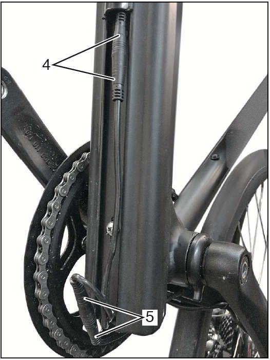
39Remove the battery
- The cable plugs (4) and( 5) are - All four screws (6) from the frame
- The battery (7) with controller (8) from the
disconnected. remove.
Pull out frame housing downwards.
40Remove the battery
Disconnect the battery (7) and controller (8)
DANGER NOTE
- Carefully remove both clips (9) from the The installation of the complete battery is
battery by a matching screwdriver press done as the converse way for the
down and the controller (8) decrease. disassemble .
- Carefully place the controller (8) on the
battery (7), Put on the clip (9)
41Technical Data
Model Pluto R / Pluto C2
General
Type Pedelec
Curb weight approx. 16.5 kg depending on equipment
Perm. Total weight max. 120 kg
Dimensions (L x W x H) mm 1870 x 630 x 1210
Top speed about 32 km / h
Frame aluminum trekking frame 28 "
Tires front and rear 700C x 28C
Rims front and rear 700C x 36H
Tire pressure front and rear min. 3.5 bar
Brake, front TEKTRO disc brake
Brake, rear TEKTRO disc brake
Driving
Front sprocket set 48 teeth
Chain sprocket rear 11 - 32 teeth
Chain 1/2 x 3/32 108 links
Pedal drive pedals
Bottom bracket cassette bottom bracket with external speed sensor (12-point magnetic
sensor)
Shift SHIMANO ALTUS , 9-speed derailleur, operated by
Shift lever on the handlebar
Display Display with display for program selection and remaining capacity
display,odometer, trip odometer
Mode 9 modes with speed limit
From approx. 25 km / h there is no more motor support Start-up and
pushing assist 6 km / h
42Technical Data
Model Pluto R / Pluto C2
Motor Drive unit Brushless three - phase motor - rear wheel motor
Rated voltage 36 volts
Rated power 350 W
Pedelec mode pedal assist
Rechargeable lithium-ion batteries
Voltage 36 volts
Peak current 15 A
Nominal capacity / rated power 7.8Ah / 280.8 Wh
Weight approx. 3 kg
Range with engine operation at a total weight from 25 km to 55 km in pedelec operation
of about 100 kg, correct air pressure, level
Roadway without strong
Head wind etc.
Lifespan depending on battery charge / battery treatment about 500 to 1,000 charging cycles
Charger mains voltage 100-230 V / 50-60 Hz, CE-compliant
Charging voltage / charging current 41.9V / approx. 2A
Display by LED red / green
Weight approx. 550 g
Charging time with empty battery approx. 5 hours / up to 80% battery capacity approx. 2.5 hours
43Vehicle Unpacking and Assembling
1. Unpacking the packaging box and making an inventory of accessories.
2. Taking out the vehicle from the packaging box, clipping the ribbons which used on front wheel and handlebar, dismantling the pearl wool
cover on vehicle.
443. And then fixing the guard support stick with cross head screws at the lower leg of front fork.
4. Fix the front disc brakes with the inner six screws on the front fork disc brake mount. There are two installation methods: radial mounting
and axial mounting..
OR
Radial Mounting Axial Mounting
455. Tightly locking the front wheel with quick release pole on the front fork, and keeping the front wheel is on the center line of front fork.
Remove the front wheel quick release lever, fix the front wheel to the front fork, and finally tighten the quick release lever.
RBSM
Burlington, Ontario
Toll free customer service line: 1 844 202-3572
46RBSM
Burlington, Ontario
Numéro sans frais du service à la clientèle : 1 844 202-3572
Vélo électrique Manuel
Pluto R Pluto C2
47Lisez attentivement ce manuel de l'utilisa- teur Le travail ne cesse de travailler sur le déve- Symboles utilisés
loppement de tous les modèles. Nous vous
de vous familiariser rapidement avec votre prions de bien vouloir comprendre que des Les remarques importantes pour votre sécurité
modifications de la forme, de l'équipement et de sont spécialement relevées. res- pectez
véhicule. Le maniement correct, outre l'entretien et
la technique de la machine peuvent donc
la maintenance régulière du véhicule, permet de survenir à tout moment. Pour cette raison, il impérativement ces consignes pour éviter les
n'est pas possible de faire valoir des droits sur
maintenir sa valeur. blessures et les détériorations du véhicule :
la base des indications, figures et descriptions
contenues dans le présent manuel. AVERTISSEMENT
Pour des raisons de sécurité, veuillez observer
Tous les textes, figures et instructions de ce signale les dangers pour la santé et in- dique les
impérativement les informations concernant les
manuel se trouvent en état d'information au
modifications, les acces- soires et les pièces de risques possibles de blessure.
moment de l'impression. Les indications figurant
rechange.
dans ce manuel sont valables en fin de ATTENTION
. distribution. Sous réserve d'erreurs ou signale des dangers potentiels pour
le véhicule ou autres objets.
transmettez ce manuel de l'utilisateur au nouveau d'omissions.
propriétaire en cas de vente du véhicule.
La reproduction ou la traduction, même
CONSEIl
partielle, n'est pas admissible sans auto-
relève les astuces et les
risation expresse. Se réserve expressé- ment
informations.
tous les droits visés par la loi sur la propriété
intellectuelle et le droit d'auteur. Sous réserve
de modifications.
48Contenu
Vue de droite……………. …………………..50 Pression de gonflage …..….……….…..70 Entretien du véhicule / Produits
Garnitures de guidon...……………….…51 Équitation……………………….….…70-71 d'entretien……………………………... 77-78
Affichage ……………………………..52-61 Degré d'assistance...………………...….71 Elimination…………………………...…….79
Position de conduit……..………….. ….62 Autonomie avec un accu chargé……... 71 Entretien des pneus……………….…...... 80
Ajuster la selle…………..………………63 Dispositif d'assistance à la poussée…. 72 Maintenance et entretien……….……..….81
Ajustage du guidon…….………….….. 64 Freins……………………….…………….73 Maintenance et entretien…………......82-83
instructions de chargeur…………. …..65 Ranger le véhicule……………………... 73 Manivelles de pédale…………………......84
Fonctions de chargeur…..………….…. 66 Consignes de sécurité……………...74-75 Roulement de direction…………………...85
batterie de sécurité………………..…….67 Démonter la roue avant pour le Démonter l'accu…………………........ 86-88
Maniement de l'accu et du chargeur…..68 transport………………………………... 76 Données techniques……………..….. 89-90
Recharger l'accu….……………………..69 Transport dans la voiture…………....…76 Déballage et assemblage du véhicule 91-93
Emporter des charges avec soi ……..…77
49Vue de droite
2
1 Serrure de cadre
2 display
3 commandes du guidon 3
4 Numéro du cadre 10 1
5 Frein à disque hydraulique avant
4
6 Accu
7 Pédalier
8 Dérailleur
9
9 Moteur électrique
10 Frein à disque hydraulique arrière
8 7 6 5
50Fonctionnement et utilisation des commandes du guidon
2 3
4
1 5 6
Organes de commande de la poignée gauche
Organes de commande de la poignée droite
1. Levier de frein de la roue avant
4. Poignée fixe
2. Poignée fixe
5. 9 levier de vitesses
3. écran
6. Levier de frein de la roue arrière
51Nom et modèle de produit
Affichage intelligent pour vélo électrique; modèle KD580.
Spécifications
●Bloc d’alimentation 24 V/36 V/48 V
●Courant nominal 10 mA
●Courant
Courant maximal de fonctionnement 30 mA
●Courant de fuite lorsqu’éteintRésumé des fonctions et définition des boutons Fonctionnement général
◆Résumé des fonctions
Le KD580 offre de nombreuses fonctions pour répondre aux
besoins des utilisateurs. Les contenus des indications sont les
suivants :
●Indicateur
Indicateur de contrôle de charge de la batterie
●Indication du niveau d’assistance
●Indication
Indication de la vitesse (incluant la vitesse du parcours, la
vitesse maximaleet de la vitesse moyenne)
●Indicateur de puissance débitée e par le moteur
●Indication de la durée du voyage ◆Mise en marche/arrêt du vélo lo électrique
●Distance parcourueet distance totale Pour mettre le système du vélo électrique en marche, maintenir le
●Fonction d’assistance à la poussée bouton MODE pendant 2 secondes.
●Mise en marche/arrêt du rétroéclairage De la même manière, en maintenant à nouveau le bouton MODE
●Indication des codes d’erreur pendant 2 secondes, le système du vélo électriques’éteindra.
●Réglages des divers paramètres tres (par exemple,taille des roues, Lors de l’extinction du système du vélo électrique, le courant de
limite de vitesse,
sse, barre de charge de la batterie, niveau PAS, activer fuiteest inférieur à1 uA.
le mot de passe, courant limité par le contrôleur, etc.) ■Lors du stationnement du vélo lo électriquependant plus de 10
●Récupération des réglages par défaut minutes, le système du vélo électriques
lectriques’éteindra automatiquement.
◆Interface de l’affichage
◆Définition des boutons Après avoir mis le système du vélo électrique en marche,
Il y a trois boutons ( )sur l’affichage du KD580 qui l’affichageindiquela vitesse du parcours. En condition de parcours,
représentent les fonctions suivantes respectivement :MODE, UP pour changer l’information indiquée, appuyer sur le bouton MODE
etDOWN. pour afficher alternativement comme suit :Vitesse du parcours
(Km/h) →Distance
Distance parcourue (Km) →Temps de déplacement
(Heure) →Vitesse
Vitesse moyenne (Km/h) →Vitesse maximale (Km/h).
Chaque état s’afficherapendant
afficherapendant 6 secondespuis retournera
retourner
automatiquementà l’interface
interface de vitesse du parcours. À condition
que la vitessesoit0 km/h, la a distance parcouruesera ajoutée
àl’interface de circulation.
53Pour allumer le rétroéclairage de l’affichage, maintenir le bouton UP
pendant 2 secondes.
De la même manière, en maintenant à nouveau le bouton UP
pendant 2 secondes, le rétroéclairage s’éteindra.
◆Sélection du niveau d’assistance
L’interface de circulation de la condition que la vitesse est de 0 km/h Les niveaux d’assistanceindiquent la puissance débitée par le
◆Basculement marche/arrêt du mode d’assistance à la poussée moteur. La valeur par défautest le niveau«1. »
Pour accéder au mode d’assistance à la poussée, maintenir Les gammes de puissance par défaut vont du niveau
toujours le bouton DOWN, le vélo électrique ira à une vitesse «0»auniveau«9. » La puissance débitéeestde zéroauniveau«0. »La
uniforme de 6 Km/h et« P » s’affichera simultanément sur l’écran. La puissance est minimale au niveau«1.»La puissance est maximale
fonction d’assistance à la poussée s’éteindra aussitôt que vous au niveau«9.»
relâcherez le bouton DOWN.
Mode d’assistance à la poussée Niveau d’assistance “4”
■La fonction d’assistance à la poussée peut seulement être utilis
ée lors de la poussée du vélo électrique. Il y a un risque de blessure
si les roues du vélo électrique ne sont pas en contact avec le sol
alors qu’on tenterait d’utiliser la fonction d’assistance à la
poussée.
◆Basculer entre lamise en marche/arrêt du rétroéclairage
54◆Indicateur de puissance du moteur ■Rapporter l’affichageà un centre de ◆Effacement de la distance parcourue
La puissance débitéepar lemoteurpeut être servicesi un code d’erreur apparaît. Effacer la distance parcourue (Clear
indiquéesurl’affichage. Réglages généraux Trip)représente un seul effacement de la
Après avoir mis le système du vélo distance parcourue. Appuyer sur le bouton
électriqueen marche, pour accéder au UP ouDOWN pour choisirYES (oui)ouNo
(non)pour effacer ladistance parcourue. La
menu des réglages généraux, maintenir
valeur par défaut estNo (non). Si on
enfoncé les deux boutons UPetDOWN
sélectionneYES (oui)et qu’on appuie sur le
pendant 2 secondes..
Interface indicateur de puissance du moteur bouton MODE pour confirmer cette option,
Appuyer sur le bouton Up ouDOWN
◆Indication des codes d’erreur l’affichage indiquera OK, puis retournera à
pour sélectionnerle contenu, appuyer sur le
Si des erreurs sont présentes dans le l’interface de sélection des réglages.
système de contrôle électronique, le code bouton MODE pour confirmer les réglages
Autrementl’affichageretournera directement
d’erreur apparaîtra automatiquement. Voici correspondants.
à l’interface de sélection des
le message du code d’erreur dans la Liste réglagesgénéraux. Pour les définitions
des divers symboles, se référer àliste 3.
Indication des codes d’erreur Effacement de la distance parcourue
Interface de sélection des réglages
généraux
55You can also read