Ultra Low Temperature Freezers - TSX series Installation and Operation - Visit us online to register your warranty ...
←
→
Page content transcription
If your browser does not render page correctly, please read the page content below
Ultra Low
Temperature Freezers
TSX series

Installation and Operation

328442H01     Rev. J   April 2019

    Visit us online to register your warranty
    www.thermofisher.com/labwarranty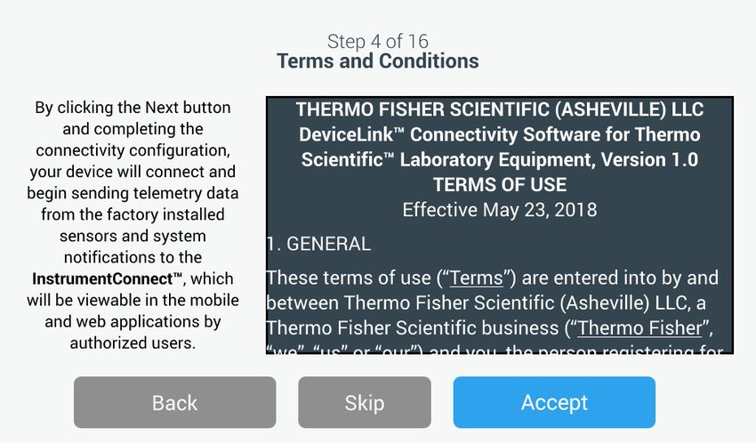
IMPORTANT Read this instruction manual. Failure to follow the instructions in this manual can result
in damage to the unit, injury to operating personnel, and poor equipment performance.

CAUTION All internal adjustments and maintenance must be performed by qualified service personnel.

Material in this manual is for informational purposes only. The contents and the product it describes are
subject to change without notice. Thermo Fisher Scientific makes no representations or warranties with
respect to this manual. In no event shall Thermo be held liable for any damages, direct or incidental,
arising from or related to the use of this manual.

© 2019 Thermo Fisher Scientific Inc. All rights reserved.
Contents

Contents
Models .......................................................................................1
Safety Precautions....................................................................2
Unpacking.................................................................................4
Packing List ..............................................................................5
General Recommendations .....................................................6
   Temperature Monitoring ...................................................... 6
   General Usage ...................................................................... 6
   Initial Loading...................................................................... 6
   Battery Door Opening / Closing .......................................... 7
Operating Standards ...............................................................8
   Electrical Specifications....................................................... 8
Installation................................................................................9
   Location ............................................................................... 9
   Wiring .................................................................................. 9
   Leveling ............................................................................. 10
   Backup System (Optional) ................................................. 10
   Super Insulated Cabinet Construction................................ 10
   Door Operation .................................................................. 10
   Pressure Equalization Port ................................................. 12
   Installing the Remote Alarm Connector ............................ 12
   Intended Use ...................................................................... 13
Start Up...................................................................................14
   Connectivity Requirements................................................ 14
   Initial Start Up.................................................................... 16
   Standby Mode .................................................................... 29
Operation................................................................................30
   Operation Overview........................................................... 30
   Home Screen ...................................................................... 30
   Settings............................................................................... 31
   Event Log........................................................................... 43
   Alarms................................................................................ 45
   Users................................................................................... 45
   Reports ............................................................................... 48
   Chart................................................................................... 49
Health Status and Alarm Management ...............................53
   Health Status Overview ..................................................... 53
   Notifications / Cautions ..................................................... 55
   Alarms / Warning............................................................... 57
Contents

           Backup System (Optional) ....................................................58
             CO2 and LN2 Precautions ................................................. 58
             Installation.......................................................................... 59
             Start Up .............................................................................. 60
             Operation............................................................................ 60
           Chart Recorders (Optional) ..................................................61
             Set Up and Operation......................................................... 61
             Changing Chart Paper ........................................................ 62
             Calibration Adjustment ...................................................... 62
           Maintenance and Troubleshooting.......................................63
             Cleaning the Condenser ..................................................... 63
             Cleaning the Condenser Filter............................................ 63
             Gasket Maintenance........................................................... 63
             Defrosting the Freezer........................................................ 64
             Battery Maintenance .......................................................... 64
             Maintenance Schedule ....................................................... 65
           Troubleshooting Guide..........................................................66
           ConnectivityTroubleshooting ...............................................70
           Warranty ................................................................................72
           Warranty (International) ......................................................73
           Appendix A: Alarm Summary .................................................74
           Appendix B: Event Log Detail .................................................81
           Appendix C: City Time Zone ...................................................83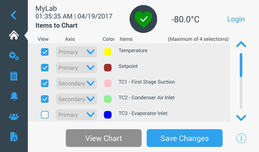
Models

                      1 Models
                                                  Brand - Model                         Size (xxx)                 Voltage (*)
                                                  Thermo Scientific – TSXxxx86*         400 / 500 / 600 / 700      A/ D /V/ G

                                                 * Note: Energy Star is not applicable to the G and V models.

Thermo Fisher Scientific Ultra Low Temperature                                                        Installation and Operation   1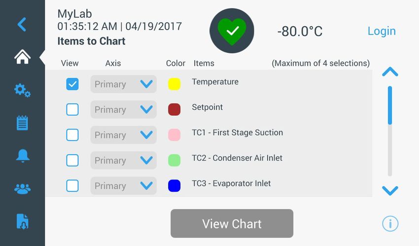
Safety Precautions

2 Safety Precautions                In this manual, the following symbols and conventions are used:

                                    This symbol used alone indicates important operating instructions which
                                    reduce the risk of injury or poor performance of the unit.

                                    CAUTION: This symbol, in the context of a CAUTION, indicates a
                                    potentially hazardous situation which if not avoided could result in minor to
                                    moderate injury or damage to the equipment.

                                    WARNING: This symbol indicates potentially hazardous situations which,
                                    if not avoided, could result in serious injury or death.

                                    WARNING: This symbol indicates situations where dangerous voltages
                                    exist and potential for electrical shock is present.

                                    The snowflake symbol indicates extreme low temperatures and high risk of
                                    frostbite. Do not touch bare metal or samples with unprotected body parts.

                                    This symbol indicates a need to use gloves during the indicated procedures.
                                    If performing decontamination procedures, use chemically resistant gloves.
                                    Use insulated gloves for handling samples and when using liquid nitrogen.

                                    Before installing, using or maintaining this product, please be sure to read
                                    this manual and product warning labels carefully. Failure to follow these
                                    instructions may cause this product to malfunction, which could result in
                                    injury or damage.

2      Installation and Operation                                        Thermo Fisher Scientific Ultra Low Temperature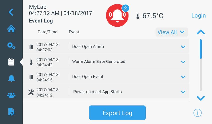
Safety Precautions

                                                 Below are important safety precautions that apply to this product:

                                                 Use this product only in the way described in the product literature and in
                                                 this manual. Before using it, verify that this product is suitable for its
                                                 intended use. If this equipment is used in a manner not specified by the
                                                 manufacturer, the protection provided by the equipment may be impaired.

                                                 Do not modify system components, especially the controller. Use OEM
                                                 exact replacement equipment or parts. Before use, confirm that the product
                                                 has not been altered in any way.

                                                 WARNING: Your unit must be properly grounded in conformity with
                                                 national and local electrical codes. Never connect the unit to overloaded
                                                 power sources.

                                                 WARNING: Disconnect the unit from all power sources before cleaning,
                                                 troubleshooting, or performing other maintenance on the product or its
                                                 controls.

                                                 WARNING: “Caution, risk of fire”. This unit is charged with hydrocarbon
                                                 refrigerants.

Thermo Fisher Scientific Ultra Low Temperature                                                     Installation and Operation    3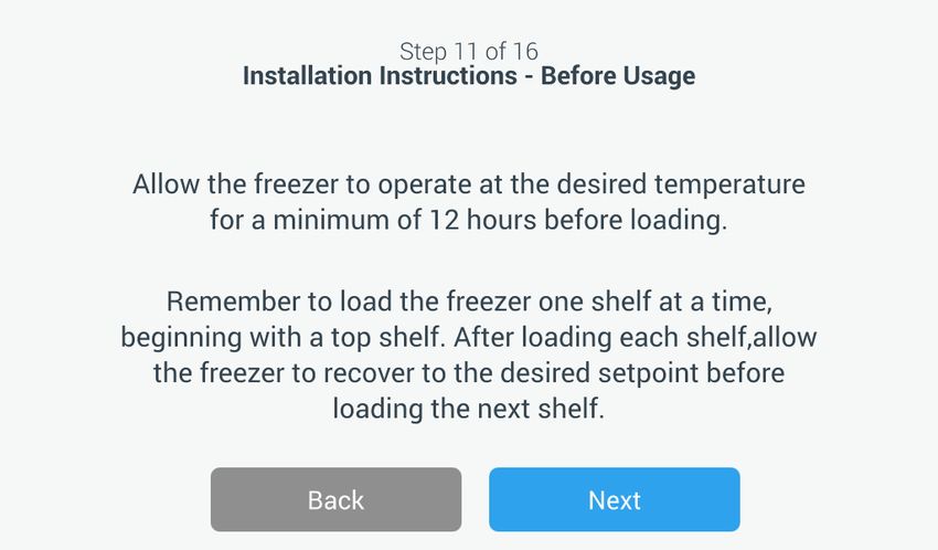
Unpacking

              3 Unpacking          At delivery, examine the exterior for physical damage while the carrier’s
                                   representative is present. If exterior damage is present, carefully unpack and
                                   inspect the unit and all accessories for damage.

                                   If there is no exterior damage, unpack and inspect the equipment within five
                                   days of delivery. If you find any damage, keep the packing materials and
                                   immediately report the damage to the carrier. Do not return goods to the
                                   manufacturer without written authorization. When submitting a claim for
                                   shipping damage, request that the carrier inspect the shipping container and
                                   equipment.

4     Installation and Operation                                         Thermo Fisher Scientific Ultra Low Temperature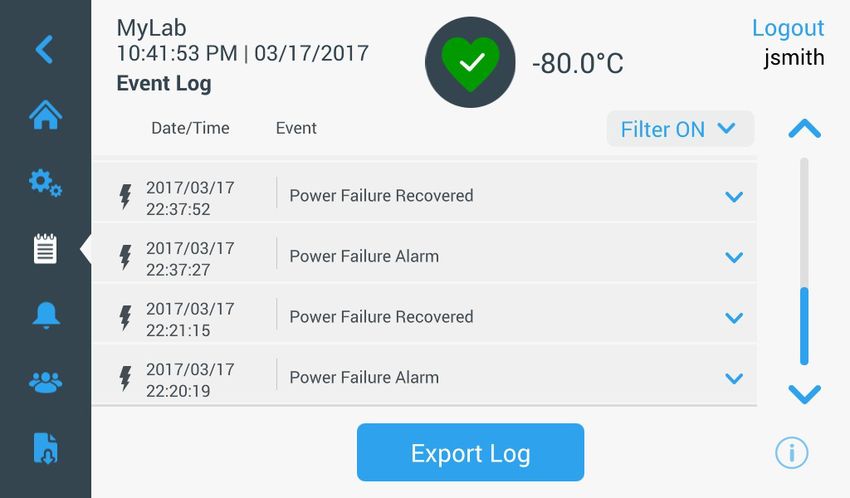
Packing List

            4 Packing List                       Inside the freezer cabinet is a bag containing:

                                                 •   This manual

                                                 •   A handle lock key

                                                 •   USB drive with user’s manuals, including translated versions

                                                 •   Certificates of conformance and calibration

                                                 •   A remote alarm contact connector

                                                 •   Posts for rear spacing

                                                 If you have ordered a field-installed chart recorder, the bag will also contain:

                                                 •   Recorder installation instructions

                                                 •   Extra inkless paper

                                                 If you have ordered a backup system, the cabinet will also contain:

                                                 •   A hose assembly

                                                 •   English and metric connectors

                                                 If specified on the order, the bag may also include:

                                                 •   A QC temperature graph and test log

                                                 •   Calibration information

                                                 If you have ordered the Proximity Access Card Option, the cards will be in a
                                                 bag attached to the front of the freezer.

Thermo Fisher Scientific Ultra Low Temperature                                                       Installation and Operation    5
General Recommendations

          5 General
    Recommendations

            5.1 Temperature
                 Monitoring
                                   IMPORTANT NOTE:We recommend the use of a redundant and
                                   independent temperature monitoring system so that the freezer can be
                                   monitored continuously for performance commensurate with the value of
                                   product stored.

         5.2 General Usage         This refrigeration system is designed to maintain ultra-low temperatures
                                   with safety in an ambient environment within 15°C to 32°C (59°F to 90°F),
                                   only when the freezer is used for storage. For TSX 700 models, the
                                   maximum operating environment is 28°C (83°F).

                                   WARNING: This unit is not a “rapid-freeze” device. Freezing large
                                   quantities of liquid, or high-water content items, will temporarily increase
                                   the chamber temperature and will cause the compressors to operate for a
                                   prolonged time period.

                                   Avoid opening the door for extended time periods since chamber
                                   temperature air will escape rapidly. Also, keep the inner doors closed as
                                   much as possible. When room air, which is higher in humidity, replaces
                                   chamber air, frost may develop in the chamber more rapidly.

         5.3 Initial Loading       Allow the freezer to operate at the desired temperature for a minimum
                                   of 12 hours before loading.

                                   Load the freezer one shelf at a time, beginning with the top shelf. After
                                   loading each shelf, allow the freezer to recover to the desired set point before
                                   loading the next shelf. Repeat this process until the freezer is fully loaded.

                                   CAUTION: Failure to follow these procedures or overloading the unit may
                                   cause undue stress on the compressors or jeopardize user product safety.

6     Installation and Operation                                          Thermo Fisher Scientific Ultra Low Temperature
General Recommendations
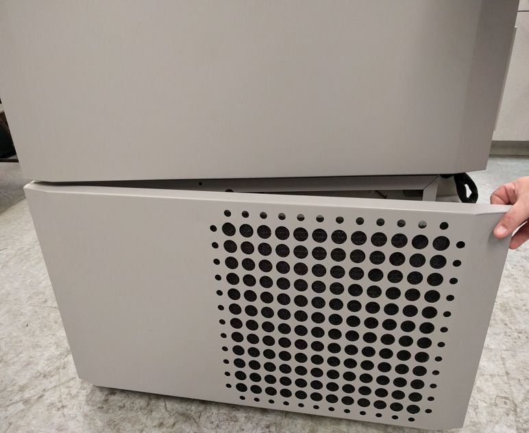
5.4 Battery Door To open the grille door, pull the door from the top right corner as shown in
Opening / Closing the figure below.
To close the grille door, push the door against frame to hold latch in
position.
Figure 1. Door Opening
Thermo Fisher Scientific Ultra Low Temperature Installation and Operation 7Operating Standards
6 Operating The freezers described in this manual are classified for use as stationary
Standards equipment in a Pollution Degree 2 and Over voltage Category II
environment.
These units are designed to operate under the following environmental
conditions:
• Indoor use
• Altitude up to 2000 m
• Maximum relative humidity 60% for temperatures within 15°C to 32°C
(59°F to 90°F). For TSX 700 models, the maximum operating
environment is 28°C (83°F).
• Main supply voltage fluctuations not to exceed ±10% of the nominal
voltage.
• For the TSX series, the ULT should not be connected to a GFCI
(Ground Fault Circuit Interrupter) protected outlet as it may be subject
to nuisance tripping.
6.1 Electrical The last character in the model number listed on the dataplate identifies the
Specifications electrical specifications for your unit. Specific unit current rating is listed on
the dataplate.
The voltage types are A, D, V and G as specified in the following table:
Table 1. TSX Series Electrical Specifications
Model Voltage Frequency Current
400D/V 208-230 V 50/60 Hz 4.0 A
400A 115 V 60 Hz 9.0 A
400G 100 V 50/60 Hz 10.5 A
500D 208-230 V 60 Hz 5.1 A
500V 208-230 V 50 Hz 5.2 A
500A 115 V 60 Hz 9.5 A
500G 100 V 50/60 Hz 9.5 A
600D/V 208-230 V 50/60 Hz 4.0 A
600A 115 V 60 Hz 8.5 A
600G 100 V 50/60 Hz 9.5 A
700D 208-230 V 60 Hz 5.8 A
700V 208-230 V 50 Hz 6.1 A
700A 115 V 60 Hz 10.6 A
8 Installation and Operation Thermo Fisher Scientific Ultra Low TemperatureInstallation
7 Installation
WARNING: Do not exceed the electrical rating printed on the data plate
located on the lower left side of the unit.
7.1 Location Install the unit in a level area free from vibration with a minimum of 8 inch
(20 cm) of space on the top and sides, 6 inch (15 cm) in back. Refer to
Section 7.3 for further instructions on leveling cabinets. Allow enough
clearance so that door can swing open at least 85°.
The rear spacing posts provided with the freezer can be used to ensure
proper clearance. To install the spacing posts, screw them into the back in
the rear deck area.
Do not position the equipment in direct sunlight or near heating diffusers,
radiators, or other sources of heat. The ambient temperature range at the
location must be 15°C to 32°C (59°F to 90°F). For TSX 700 models, the
maximum operating environment is 28°C (83°F).
7.2 Wiring
CAUTION: Connect the equipment to the correct power source. Incorrect
voltage can result in severe damage to the equipment.
CAUTION: For personal safety and trouble-free operation, this unit must
be properly grounded before it is used. Failure to ground the equipment
may cause personal injury or damage to the equipment. Always conform to
the National Electrical Code and local codes. Do not connect the unit to
overloaded power lines.
CAUTION: Do not position the unit in a way that impedes access to the
disconnecting device or circuit breaker in the back of the unit.
CAUTION: Always connect the freezer to a dedicated (separate) circuit.
Each freezer is equipped with a service cord and plug designed to connect it
to a power outlet which delivers the correct voltage. Supply voltage must be
within ±10% of the freezer rated voltage.
CAUTION: Never remove or disable the grounding prong from the service
cord plug. If the prong is removed, the warranty is invalidated.
Thermo Fisher Scientific Ultra Low Temperature Installation and Operation 9Installation
7.3 Leveling Make sure that the floor is level. The unit must be level both front to back
and side to side.
400 box capacity models are equipped with one leveling leg on the right
hand side. These may be used to help prevent the unit from shifting during
a door opening.
Be certain to lock the brakes for units equipped with casters.
7.4 Backup System If you are using a CO2 or LN2 backup system, refer to Section 11 for
(Optional) installation and operation instructions.
7.5 Super Insulated In all models, the cabinet walls have a vacuum insulation core encapsulated
Cabinet Construction by a sealed film laminate.
CAUTION: Never drill holes in or near the cabinet walls. Drilling could
damage the insulation and make the unit inoperable.
7.6 Door Operation Upright freezer models are equipped with an advanced assembly specifically
designed for ultra-low temperature freezers.
Features include:
• One-hand operation
• A front-accessible lock
• Hasps for a standard padlock to provide additional security. Length of
the shackle must be between 3/4 inch (1.9 cm) and 11/2 inch (3.8 cm).
• Durable construction for reliable operation and safe product storage.
• Door ramp alignment feature
• Optional controlled access to the freezer with Proximity Access cards.
CAUTION: When moving the freezer, always grasp cabinet surfaces; never
pull the freezer by the latch handle.
7.6.1 Opening the Door For freezers with the Proximity Access Card option:
1. Remove the padlock if installed.
10 Installation and Operation Thermo Fisher Scientific Ultra Low TemperatureInstallation
2. To unlock the door, pass the card in front of the freezer below the LCD
display.
3. Grasp the latch handle and pull it toward yourself until the latch
disengages from the cabinet strike.
4. Keep pulling by the latch handle to open the main door.
For freezers without the Access Card option:
1. Remove the padlock if installed.
2. Grasp the latch handle and pull it toward yourself until the latch
disengages from the cabinet strike.
3. Keep pulling by the latch handle to open the main door.
7.6.2 Opening the Door During In case of power outage and a unit that has the Proximity Access Card
a Power Outage option, you may use a 9 volt battery to activate the system. To access the
9 volt terminal, remove the USB cover and locate the battery terminals.
Once the terminals are exposed, open the door by holding the 9 volt battery
against the terminals and pass a valid proximity card below the display area.
Once the door is open, remove the 9 volt battery.
Note: The terminals are polarized therefore orient the 9 volt battery properly.
7.6.3 Closing the Door Note: The latch does not self-engage automatically when you close the door. You
must rotate the latch into the open position first.
1. Grasp the latch handle (preferably with your left hand) and pull it
toward yourself, rotating the latch into the open position.
2. Move the freezer door into the closed position and gently push the
handle away from you, making sure that the latch engages fully with the
cabinet strike.
3. Keep applying gentle pressure to the latch handle until the latch is
securely in closed position.
4. Insert the key and rotate counterclockwise to lock.
5. Replace the padlock as required.
Thermo Fisher Scientific Ultra Low Temperature Installation and Operation 11Installation
7.7 Pressure When an upright ultra-low temperature freezer door is opened, room
Equalization Port temperature air rushes into the storage compartment. When the door is
closed, the fixed volume of air is cooled rapidly. Pressure drops below
atmospheric pressure, resulting in a substantial vacuum. Re-entry into the
cabinet is impossible until internal pressures are returned to atmospheric
pressure. Without a pressure equalization mechanism, it can take, in
extreme cases, several hours before the door can easily be reopened.
All upright models feature a port that provides vacuum relief after door
openings. The pressure equalization port is located in the door behind the
eye-level panel on the front of the freezer. Although the port is designed to
self-defrost, excessive frost accumulation on the inner door could eventually
restrict air flow. Therefore you should periodically inspect the inner door
and brush away any loose frost using a stiff nylon brush.
7.8 Installing the The remote alarm contacts are located on the back of the freezer above and
Remote Alarm to the left of the power switch. After installing the wiring from the remote
alarm to the connector, install the connector to the freezer micro-board.
Connector
The pin configuration is shown in Figure 2 below.
Figure 2. Remote Alarm Pin Configuration
The contacts will trip in the event of a power outage, high temperature
alarm, low temperature alarm or door ajar alarm.
12 Installation and Operation Thermo Fisher Scientific Ultra Low TemperatureInstallation
7.9 Intended Use The –86°C freezer (refer to Section 1 for the specific model series) described
in this manual are high performance units for professional use. These
products are intended for use as cold storage in research use and as a general
purpose laboratory freezer, storing samples or inventory at operating
temperatures between –50°C and –80°C.
It is not considered a medical device and has therefore not been registered
with a medical device regulatory body (e.g. FDA): that is, it has not been
evaluated for the storage of samples for diagnostic use or for samples to be
re-introduced to the body.
This unit is not intended for use in classified hazardous locations, nor to be
used for the storage of flammable inventory.
Thermo Fisher Scientific Ultra Low Temperature Installation and Operation 13Start Up
8 Start Up
8.1 Connectivity There are two requirements to take full advantage of your freezers
Requirements connectivity options:
1. The freezer will need to be connected to a wireless network with internet
connection, the freezer is only able to use a wireless connection.
a. Refer to WiFi Specification table in Section 8.1.1 for acceptable
network security parameters.
b. Please speak with your local Information Technology (IT) group
about the correct wireless network and password to use.
2. The individual monitoring the unit will need a Thermo Fisher Connect
account and will need to link the unit to his/her account via
InstrumentConnect™. To create a Thermo Fisher Connect account:
a. Use a web browser to open the following URL:
https://apps.thermofisher.com
b. Choose "Create an Account" and follow the instructions to establish
a new account. (Remember your login information for later use.)
c. (Optional) Download the InstrumentConnect mobile/tablet
application from the AppStore or PlayStore.
Note: InstrumentConnect™ is the section of Thermo Fisher Connect where all
connected instruments can be monitored. To access this section, click on the
InstrumentConnect icon indicated below.
Note: If you are a user in China, the web client allows you to switch to that
region after logging in or you can log in directly to the China environment by
using https://china.apps.thermofisher.com.
14 Installation and Operation Thermo Fisher Scientific Ultra Low TemperatureStart Up
8.1.1 Specifications
Table 2. Specifications
Parameter Specification
Every 5 minutes for sensor
Default Wi-Fi transmission frequency to the cloud data transmission.
Real-time for alarm events
2.4 GHZ only: IEEE
WiFi protocol 802.11B, IEEE 802.11G,
IEEE 802.11N
WPA / WPA2PSK
WPA / WPA2EAP
Wi-Fi Security PEAP
Proxy servers are not
supported.
Wi-Fi Data Rate Minimum of 1 Mbps
Wi-Fi Range Up to 30 meters
Minimum Required Wireless Signal -70 dbM
Firewall Ports that must open 80, 123, 443
Note: Thermo Fisher Scientific connected devices do not support the use of proxy
servers or enterprise networks which require identity/username for internet
access.
8.1.2 In case of Failure If your freezer is unable to connect to either a wireless network or a cloud
account, please verify your name and password, and attempt to re-connect.
If issues persist, please contact Your Local Support.
Note: If your network password expires or changes, your freezer will no longer
connect automatically. Be sure to manually update your password in the freezer
user interface settings to reconnect. Failure to reconnect within 3 days will result
in data loss.
Thermo Fisher Scientific Ultra Low Temperature Installation and Operation 15Start Up
8.2 Initial Start Up To start up the freezer, complete the following steps:
1. Plug the freezer into the power outlet.
2. Turn the power switch in back of the freezer, on the bottom right, to the
ON position.
3. Once the freezer is powered up, the Thermo Scientific logo is displayed
on the front screen. If this is the first time the unit is being turned on, an
initial setup must be completed. Press the Start Setup button to initiate
the setup.
Figure 3. Main Screen
The first step of the setup is to select the language. This screen allows you to
specify the preferred display language. Once the language is selected, press
the Next button.
Figure 4. Language Selection Screen
The next screen allows you to select your location. Enter the name of the
city and select from the list of suggestions displayed.
16 Installation and Operation Thermo Fisher Scientific Ultra Low TemperatureStart Up
After selecting the region, press the Next button.
Figure 5. Region Setup Screen
When entering your “City” into Region Setup screen, refer to “Appendix C: City
Time Zone” . Follow the table to select the city closest to your time zone.
The next screen allows you to identify an individual freezer by specifying a
Unit Name. After entering a name, press the Next button.
Figure 6. Unit Name Setup Screen
The next few screens allow you to setup a wireless connection to store
information on InstrumentConnect.
To fully connect your new unit, you will need to:
1. Connect the unit to a wireless network allowing data to be sent to
Thermo Fisher Connect.
2. Log in to Thermo Fisher Connect (web or app) and link the unit to
your account via InstrumentConnect.
Thermo Fisher Scientific Ultra Low Temperature Installation and Operation 17Start Up
Note: Before you begin, establish a Thermo Fisher Connect account and have
your network login information available. Refer to section Section 8.1 for
details.
The first screen requires acceptance of the terms and conditions of using
connectivity on this device.
If you chose to Skip this acceptance, Wi-Fi connectivity will be disabled.
You will be able to accept the terms and enable connectivity at a later time
via the Connectivity settings menu.
Figure 7. Terms and conditions screen
Select a wireless network and press the Next button.
Figure 8. Wireless Setup Screen
Once the intended network is selected (highlighted), you must press the
Next button.
Note: If you do not want to setup a wireless connection, press the Skip button.
The Date and Time Setup screens will appear. To setup a wireless connection
later, press the Settings menu icon and select Connectivity.
18 Installation and Operation Thermo Fisher Scientific Ultra Low TemperatureStart Up
Enter the network password and press the Next button.
Figure 9. Wireless Setup (Password) Screen
Note: Press the eye icon on the screen for password visibility
Note: The on-screen keyboard does not support all special characters. Please
inquire with your local IT group for assistance with password reset to
accommodate allowable character entry.
Figure 10. On Screen Key board
Thermo Fisher Scientific Ultra Low Temperature Installation and Operation 19Start Up
Figure 11. On Screen Key-board
A success message is displayed once the connection is established. If the
connection fails, either due to an incorrect Wi-Fi password or network
unavailability, a general error message is displayed. After 5 seconds, the
interface will return to the previous screen.
If this occurs, check the network status and re-enter the correct password to
establish the connection. (Tip: use the eye icon to verify the password entry
before attempting connection.)
Refer to Section 15 for more connectivity troubleshooting.
Figure 12. Wireless Setup Error Message Screen
20 Installation and Operation Thermo Fisher Scientific Ultra Low TemperatureStart Up
Figure 13. Wireless Setup Success Message Screen
The Network Configuration screen appears after a successful connection is
established, which displays the time and date based on the wireless network.
Verify the information displayed and press the Next button.
Figure 14. Network Configuration Screen
The next screen displays three options to connect your unit to
InstrumentConnect. You can store historical data and receive alarm
notifications to your InstrumentConnect account.
Figure 15. Connect to the InstrumentConnect Screen
Thermo Fisher Scientific Ultra Low Temperature Installation and Operation 21Start Up
Connect via Mobile Device
Selecting the Connect via Mobile Device option displays the following
screen. Follow the instructions to connect to InstrumentConnect.
Figure 16. Connect to the InstrumentConnect (via Mobile Device)
Screen and Mobile Device Screens
Connect via Passcode
This option displays a code that has to be entered to connect to
InstrumentConnect.
Figure 17. Connect to the InstrumentConnect (via Passcode) Screen
22 Installation and Operation Thermo Fisher Scientific Ultra Low TemperatureStart Up
Connect via user name
Sign in using your InstrumentConnect user name and password and press
the Link Account button.
Figure 18. Connect to the InstrumentConnect (via user name) Screen
If the connection is successful via any of the three methods, a success
message is displayed.
Note: If a connection is established, and you choose to connect the unit with
additional user InstrumentConnect accounts, you can press the Back button and
repeat the same process. If you go back and then decide not to continue an
additional connection setup you will need to press the Skip button on the
connection screen (See Figure 15). This will not remove any established
connections previously created. You can also add additional connections via
the Connection Settings menu after initial start-up is complete.
If the connection is unsuccessful, an error message is displayed. After 5
seconds, the interface will return to the previous screen. Check the network
status and any entered passwords, etc. and repeat the previous steps to
establish a successful unit connection.
Refer to Section 15 for more connectivity troubleshooting.
Thermo Fisher Scientific Ultra Low Temperature Installation and Operation 23Start Up
The next screen allows you to specify the temperature unit. After selecting
the unit, press the Next button.
Figure 19. Units Setup Screen
The next three screens provide installation instructions.
The first screen provides information regarding power source and ambient
temperature conditions. Press the Next button to continue through the
installation instructions.
Figure 20. Installation Instructions (Power and Temperature) Screen
24 Installation and Operation Thermo Fisher Scientific Ultra Low TemperatureStart Up
The second screen provides information regarding unit positioning, spacing
and leveling. Press the Next button after reviewing.
Figure 21. Installation Instructions (Positioning) Screen
The third screen provides information regarding initial freezer loading. Press
the Next button after reviewing.
Figure 22. Installation Instructions (Before Usage) Screen
The next screen allows you to specify the temperature, warm and cold alarm
setpoints. After setting the temperatures, press the Next button.
Figure 23. Setpoints and Alarms Screen
Thermo Fisher Scientific Ultra Low Temperature Installation and Operation 25Start Up
This screen allows you to select the Operating Mode. Once the mode has
been selected, press the Next button.
Figure 24. Operating Mode Setup Screen
This screen allows you to specify the Access Mode.
Figure 25. Access Mode Setup Screen
If Secured Access is selected, at least one administrative account will need to be
created.
26 Installation and Operation Thermo Fisher Scientific Ultra Low TemperatureStart Up
This screen allows you to enter the details of your first name, last name, email
and user name in the access mode set-up screen.
Figure 26. Access Mode Setup Screen
This screen indicates your initial setup is complete. Press the Finish button
to complete initial setup or the Back button to make changes.
Figure 27. Complete Setup Screen
Thermo Fisher Scientific Ultra Low Temperature Installation and Operation 27Start Up
8.3 Standby Mode There is a standby button on the front of the unit. When pressed and held
for ~3 seconds the user will be prompted to confirm that the unit should be
placed in standby mode. Upon confirmation, the unit will enter standby
mode. The refrigeration system will be shut down and the unit will not
cool while in standby mode. To exit standby mode and restore normal
operation, the standby power button must be pressed and held for ~1
second.
Standby Button
Figure 28. Standby Button
28 Installation and Operation Thermo Fisher Scientific Ultra Low TemperatureOperation
9 Operation
9.1 Operation Overview Once you have successfully completed the initial start up procedures, the
freezer starts operating normally and the only actions required are:
• Setting the operating and alarm set points, refer to Section 9.3.1.
• Activating the CO2 or LN2 backup system if installed. For instructions
on backup settings and activating the system, refer to Section 11.
9.2 Home Screen The Home Screen below is the default screen.
Figure 29. Home Screen
The various options available on the home screen are:
• The vertical panel on the left is the navigation bar that provides access to
all functions of the unit.
• The colored icon in the middle indicates the health of the unit. There
are four icons to denote this:
• Green heart with a check mark indicates operation is normal.
• Yellow triangle with an exclamation mark indicates a notification.
• Red bell indicates an alarm condition.
• Red bell with a diagonal indicates the alarm has been snoozed.
• A login button to login into the system. Refer to Section 9.2.1 for more
information.
Thermo Fisher Scientific Ultra Low Temperature Installation and Operation 29Operation
• The icons displayed below the time indicate if the unit is connected to
InstrumentConnect and Wi-Fi, signal strength, and the operating
mode.
• The setpoint temperature is displayed. This can be changed by pressing
the setpoint button at the bottom of the screen.
• The temperature chart can be viewed by pressing the Chart button at
the bottom of the screen. Refer to Section 9.8 for more information.
• The “i” icon at the bottom right corner of the screen is the onboard help
button. Press this icon to display an onboard help box with text
explaining all of the features available on that particular screen.
• The back button to navigate to the previous screen.
9.2.1 User Login When the system is in Secured Access Mode, the user has to login by
entering their user name and password.
When the system is running in Full Access mode, the login feature is
restricted to service technicians to access the Service screens.
9.3 Settings The second tab on the navigation panel is the Settings icon. The following
screen will be displayed once the Settings icon is selected:
Figure 30. Settings Screen
30 Installation and Operation Thermo Fisher Scientific Ultra Low TemperatureOperation
9.3.1 Alarms The Alarm Settings screen provides the option to set the warm and cold
alarm setpoints. Press the Warm Alarm or Cold Alarm button and the
setpoints screen will be displayed permitting parameter adjustments. For
more information, refer to Section 9.3.5.
Figure 31. Alarm Settings Screen
• Warm Alarm: The range of the warm alarm temperature is –40°C to
within 5°C of setpoint.
Note: The warm alarm will be disabled for 12 hours from a warm start
condition.
• Cold Alarm: The range is –99°C to within 5°C of setpoint.
• Extreme Ambient: This allows the user to set the extreme ambient
alarm setpoint. The range is 32°C to 40°C. Default is 37°C.
• Compressor Temperature: It is an alarm setpoint for the second stage
compressor sump temperature. The range is 70°C to 98°C. Default is
94°C.
• Snooze Timeout: This sets the time to snooze the audible alarm for an
active alarm.
Thermo Fisher Scientific Ultra Low Temperature Installation and Operation 31Operation
9.3.2 Display From the Settings screen, pressing the Display button will show the Display
screen. Various display settings can be adjusted.
Figure 32. Display Screen
• Brightness: Use the slide control or the +/– buttons to adjust the
brightness level of the display.
32 Installation and Operation Thermo Fisher Scientific Ultra Low TemperatureOperation
• Language: To change the display language, press the Language button
and select the desired language.
• Auto Date/Time: To manually set the date and time, turn this setting
off and select the format.
• Units of Measure: To change the displayed unit of measure, press the
Units of Measure button.
• Date: To set the date and the date format, press the Date button.
Figure 33. Date Screen
• Unit Name: To enter or change the unit name, press the Unit Name
button.
• Time: To set the time and time format, press the Time button.
• Icon Bar Customization: This is used to customize the bottom three
icons in the navigation bar.
• Region: This is used to set the region the unit is operating from.
• Home: To select the default home screen, press the Home button.
• Auto Time Off: Select the time range for when the LCD will
automatically darken. The default option None, will leave the LCD
constantly illuminated.
• Screen Calibration: Press to run a screen auto calibration routine.
• Screen Sensitivity: Select to modify the touch sensitivity of the screen.
Select the Save button after making the necessary changes.
Thermo Fisher Scientific Ultra Low Temperature Installation and Operation 33Operation
9.3.3 Users Access Mode is used to change the access mode for the system (full or
secured), add a user to the system, and to import and/or export a user
database.
The Users screen can also be accessed by using the User Icon on the left
navigation bar. For more information, refer to Section 9.6.
Figure 34. Users Screen
9.3.4 Files and Info The following screen is displayed when the Files and Info button is selected:
Figure 35. Files and Info Screen
• Factory Reset: Select to reset the settings, including temperature
setpoint to factory defaults.
• Configuration Files: This is used to export or import configuration
files. Configuration files may be uploaded to other freezers.
• Reports: This is used to export temperature and event data. A date range
can be provided too. Refer to Section 9.7 for more information.
34 Installation and Operation Thermo Fisher Scientific Ultra Low TemperatureOperation
• Contact Us: Press this button to view or modify the service contact
information.
9.3.5 Controls Temperature setpoints can be set in the Controls screen. To select a
temperature setpoint,
Select the Controls button to navigate to the Controls screen.
Figure 36. Controls Screen
• Operating Mode: The default setting is the Standard mode, which
provides a balance between power consumption and peak variation
performance. High Performance mode provides minimum temperature
peak variation.
Note: Customers performing on-site temperature calibration may observe as
much as a 2°C variation when an external probe is placed next to the freezer
control probe. This variation is due to optimization of the control system to
ensure temperature uniformity throughout the chamber.
• Power Recovery Delay: Press this button to set the time delay upon
startup after power failure. Default is 0.
• Temperature Offset: This is used for calibration. Range is –10°C to
+10°C. Default is 0.
• Backup System Settings: This screen allows the user to select the
backup type and backup setpoint for units with a backup system
installed. For more information, refer to Section 11.
Thermo Fisher Scientific Ultra Low Temperature Installation and Operation 35Operation
• Press the Temperature Setpoint button to display the Setpoints screen:
Figure 37. Setpoints Screen
• The setpoint and temperature alarm parameters may be adjusted by
swiping the spin control up / down or pressing the up / down
arrows.
Note: A setpoint change may automatically change the warm and / or cold
alarm setpoints as well to prevent unnecessary alarms.
• After selecting the temperatures, press the Save button to confirm
changes.
Note: If the save button is not pressed, the unit will not respond to the setpoint
change request.
Warm Alarm Test: Pressing this button puts the system into a warm alarm
test which simulates a warm alarm experience. Once this is selected, the
home screen is displayed with the current temperature readout. The
temperature display will increase to the warm alarm temperature setpoint.
Once the warm alarm temperature has been reached, the user is prompted
to end the test.
36 Installation and Operation Thermo Fisher Scientific Ultra Low TemperatureOperation
9.3.6 Connectivity The Connectivity tab is used to setup a wireless network and connect to
InstrumentConnect. Be sure to follow both steps to store information on
InstrumentConnect.
The following screen is displayed when the Connectivity button is selected.
Figure 38. Connectivity Screen
9.3.6.1 Wi-Fi Press the Wi-Fi button to connect to a network. Select the network from the
list and press the Next button.
Figure 39. Wi-Fi Devices Screen
Thermo Fisher Scientific Ultra Low Temperature Installation and Operation 37Operation
Enter the network password and press the Join button.
Figure 40. Join Wi-Fi Network Screen
Note: The on-screen keyboard does not support all special characters. Please
inquire with your local IT group for assistance with password reset to
accommodate allowable character entry.
Figure 41. On Screen Key board
38 Installation and Operation Thermo Fisher Scientific Ultra Low TemperatureOperation
Figure 42. On Screen Key-board
A success message is displayed once the connection is established. If the
connection fails, either due to an incorrect Wi-Fi password or network
unavailability, a general error message is displayed. After 5 seconds, the
interface will return to the previous screen.
If this occurs, check the network status and re-enter the correct password to
establish the connection. (Tip: use the eye icon to verify the password entry
before attempting connection.)
Refer to Section 15 for connectivity troubleshooting.
Figure 43. Wireless Setup Error Message Screen
Thermo Fisher Scientific Ultra Low Temperature Installation and Operation 39Operation
9.3.6.2 Removing Wi-Fi To remove an established connection first select the network you wish to
Connection disconnect from within the selection screen shown in Figure 39 and press
the Next button. On the following network information screen, press the
Forget Network button. You will be prompted to confirm your selection.
Once the connection has been disabled, the screen will return to the Wi-Fi
Device selection screen pictured in Figure 39.
Figure 44. Wireless Setup Connection Message Screen
9.3.6.3 InstrumentConnect The following screen is displayed when you select the InstrumentConnect
button in Figure 38.
Figure 45. InstrumentConnect Screen
40 Installation and Operation Thermo Fisher Scientific Ultra Low TemperatureOperation
Connect via Mobile Device
Selecting the Connect via Mobile Device option displays a screen with
instructions. Follow the instructions to connect to InstrumentConnect.
Figure 46. Connect via Mobile Device Screen and InstrumentConnect
Mobile Interface Screens
Connect via Passcode
This option displays a code that has to be entered to connect to
InstrumentConnect.
Figure 47. Connect via 1-Time Passcode Screen
Note: When using the InstrumentConnect web and mobile app, ensure you are
in the correct regional environment. If you are in China, you should select the
China region. Refer to Section 8.1 for more details.
Thermo Fisher Scientific Ultra Low Temperature Installation and Operation 41Operation
Connect via user name
Sign in using your InstrumentConnect user name and password and press
the Link Account button.
Figure 48. Connect via user name/Password Screen
If the connection is successful via any of the three methods, a success
message is displayed.
If the connection is unsuccessful, an error message is displayed. After 5
seconds, the interface will return to the previous screen. Check the network
status and any entered passwords, etc. and repeat the previous steps to
establish a successful unit connection.
Refer to Section 15 for more connectivity troubleshooting.
9.4 Event Log The third tab on the navigation panel is the event log that contains a record
of user and system events. The Event Log screen will be displayed once the
Event Log icon is pressed.
Figure 49. Event Log Screen
42 Installation and Operation Thermo Fisher Scientific Ultra Low TemperatureOperation
This screen displays up to two weeks of recent events, with date time stamps
for each event.
The Date/Time and Event columns can be sorted in an ascending or
descending order by selecting the column header.
Additional information of an individual event can be viewed by selecting the
event.
There is a drop down list based on the event types. The event types can be
filtered and categorized into: Alarm, Door, User, Battery and Backup. When
a filter is selected, the View All button on the right changes to Filter ON.
Figure 50. Event Log Screen with Filter
To export event and temperature logs,
1. Choose the item to be exported from Export drop down list. The options
available are: Event and Temperature Log, Event Log, Temperature Log and
Reports.
2. Select the export format of the log or report.
3. A predefined or custom date range may be selected.
Thermo Fisher Scientific Ultra Low Temperature Installation and Operation 43Operation
4. A USB drive must be inserted to store the log or report. Press the Export
Log button to download the log or report.
Figure 51. Export Log Screen
9.5 Alarms By selecting the Alarm tab, the Alarm Settings screen is displayed. For more
information on setpoints, refer to Section 9.3.1.
Figure 52. Alarm Settings Screen
44 Installation and Operation Thermo Fisher Scientific Ultra Low TemperatureOperation
9.6 Users The User tab is used to display the Users screen. Access Mode is used to
change the access mode for the system (full or secured), add a user to the
system, and to import and/or export a user database. The following screen is
displayed when the User icon is selected:
Figure 53. Users Screen
The Import button allows a user database to be imported.
Note: The database to be imported must be taken from another unit running
the same software otherwise the system will not recognize the database.
The user database can be exported using the Export button. A USB drive
must be inserted for the data to be transferred.
Thermo Fisher Scientific Ultra Low Temperature Installation and Operation 45Operation
9.6.1 Adding New Users Select the Add User button to navigate to the Add a User screen:
Figure 54. Add a User Screen
Fill in the information in the fields and press Add User. An asterisk denotes
a required field.
• First Name: Enter the user’s first name.
• Last Name: Enter the user’s last name.
• Email: Enter the user’s email address.
• User Name: Enter the user name as required. A default will appear based
upon the email address entered.
• Password: Enter and confirm a user password. The password entered
should be 3-16 characters long, have at least 1 uppercase, 1 number and
1 special character.
• Phone: Enter a user telephone number. Additional phone numbers can
be added by pressing the ‘+’ symbol.
46 Installation and Operation Thermo Fisher Scientific Ultra Low TemperatureOperation
• User Role: Select the access level for the user.
• Admin: This user has access to change settings and manage profiles.
• User Level 1: This user has access to change basic functionality such
as temperature and alarm setpoints.
• User Level 2: This user can view the temperature and alarm
information but cannot change the settings (Primarily used when
unit is equipped with HID Access ID, as anyone needing access to
the freezer must have a user role).
• Access ID: Refer to Section 9.6.3 for more information on access cards.
9.6.2 Editing and Deleting To edit an existing user, press the user entry in the Users screen and User
Users Details screens will be displayed. Make the required edits by selecting the
appropriate field and changing the information. After making the changes,
press the “Edit User” button and confirm.
To delete a user, select the Delete User button and confirm.
Note: This action cannot be undone.
Thermo Fisher Scientific Ultra Low Temperature Installation and Operation 47Operation
Figure 55. User Details Screen
9.6.3 Managing Access Cards When the Access Card system is installed, the User Details screen allows
assigning cards to each user. Users may then swipe their access card to gain
access to the freezer or login.
To associate an access card to a selected user, press the Access ID field of the
User Details screen (refer to Figure 55) and hold the card at the bottom
center of the LCD screen. The Access ID field will automatically be
populated and you will hear a beep. Only one card may be added per user.
The Access ID must be unique for each user.
9.7 Reports The Report tab is used to export a log or report. The Export Logs and
Reports screen will be displayed when the Report icon is pressed. If Reports
is selected as the Export type, the date range is limited to two options - one
week (default) and one day. Refer to Section 9.4 for more information.
Figure 56. Export Logs and Reports Screen
48 Installation and Operation Thermo Fisher Scientific Ultra Low TemperatureOperation
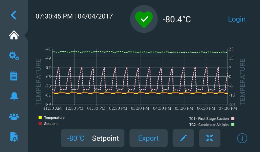
9.8 Chart The chart displays temperature data.
There can be a maximum of two Y-axis. The left Y-axis is Primary and the
right Y-axis is Secondary. Items displayed on the Primary axis are listed on
the left and the ones displayed on the Secondary axis are listed on the right.
Time is denoted on the X-axis.
Figure 57. Chart with items on Primary axis
Figure 58. Chart with items on Primary and Secondary axes
The four buttons on the bottom of the screen are used to:
• Change the setpoint
• Export the chart
• Edit the chart, refer to Section 9.8.1 for more information
• Expand the chart to full screen or return to the default view.
Thermo Fisher Scientific Ultra Low Temperature Installation and Operation 49Operation
9.8.1 Editing the Chart When the Pencil icon is selected, the Chart Edit screen is displayed:
Figure 59. Chart Edit Screen
• The X-Axis button allows the user to select a time span of 2, 4, 6 or
8 hours.
• The Items to Chart button allows the user to select the items to be
displayed on the chart. A maximum of four items may be selected.
• Show Event Overlay: Enable quick reference event icons to be displayed
on the top of the chart.
50 Installation and Operation Thermo Fisher Scientific Ultra Low TemperatureOperation
Figure 60. Items to Chart Screen
• The Primary Y-Axis button allows the user to set the temperature range.
If Auto is selected, the temperatures are automatically set. If Manual is
selected, the user has to specify the high and low temperatures.
Figure 61. Primary Y-Axis Set screen
Thermo Fisher Scientific Ultra Low Temperature Installation and Operation 51Operation
• The Secondary Y-Axis button allows the user to set the temperature
range. If Auto is selected, the temperatures are automatically set. If
Manual is selected, the user has to specify the high and low
temperatures. Item associated with the Secondary Y-Axis will be
displayed as a dotted line. The Axis On toggle button is used to enable
the Secondary Y-axis.
Figure 62. Secondary Y-Axis Set Screen
9.8.2 Event Icons Icons related to events will appear on the top of the chart.
Icon Description
Door Open
Power Failure
Temperature Alarm
Service
Multiple Events
Connected to InstrumentConnect™
Connected to Wi-Fi
52 Installation and Operation Thermo Fisher Scientific Ultra Low TemperatureHealth Status and Alarm Management
10 Health Status
and Alarm
Management
10.1 Health Status Selecting the Health Status (green heart) icon in the home screen displays
Overview the following screen:
Figure 63. Health Status Screen
• Door Openings: Total displays the number of times the door has been
opened since the last reset. Last Open displays the duration the door was
last opened. Press the Reset icon to change the Door Openings values to
0.
• Temperature Excursions: Actual displays the current cabinet
temperature. Warm and Cold displays are the highest and lowest
temperatures recorded since the last reset. Press the Reset icon to set the
Warm and Cold values to the current cabinet temperature.
• Conditions: Voltage displays the input voltage. Ambient displays the
unit ambient temperature. By pressing the Conditions Detail button the
following screen will be displayed:
Figure 64. Conditions Detail Screen
Thermo Fisher Scientific Ultra Low Temperature Installation and Operation 53Health Status and Alarm Management
• Power Modes: Displays the state of the on-board voltage conditioning
system.
• Main Battery: Displays the voltage of the main battery. There is also a
12 month countdown timer that should be reset every time the battery
is replaced.
• Backup System (BUS): The BUS information will be displayed if a BUS
is present.
Selecting the System Dashboard button in Figure 63 displays the on board
sensor readings.
Figure 65. System Dashboard Screen
When a BUS is present, the BUS RTD and BUS battery values are also
displayed.
54 Installation and Operation Thermo Fisher Scientific Ultra Low TemperatureHealth Status and Alarm Management
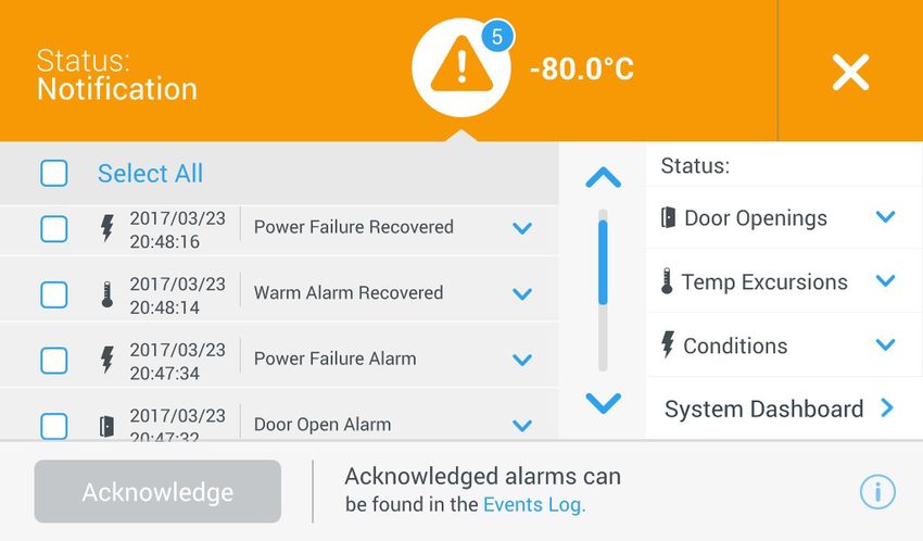
10.2 Notifications / In the event of a notification, the green heart is replaced by a yellow triangle
Cautions icon. The number in the blue circle indicates the total number of
notifications.
A yellow triangle on the home screen indicates less serious caution
conditions, such as extended door openings and alarms that occurred in the
past.
Figure 66. Home Screen with Notification / Caution
Press the yellow triangle to display additional notification details.
Figure 67. Notification / Caution Details
The Acknowledge button becomes highlighted in blue once a notification is
selected by pressing the adjacent checkbox. The notification will be
displayed until it is acknowledged. There is a link to the Event Log beside
the Acknowledge button.
On the right panel, the Health Status details can also be viewed.
Thermo Fisher Scientific Ultra Low Temperature Installation and Operation 55Health Status and Alarm Management
10.3 Alarms / Warning In the event of an alarm condition, the green heart or yellow triangle is
replaced by a red bell icon. A red bell alarm on the home screen indicates a
serious alarm condition which must be corrected, such as a warm alarm or a
power failure. The alarm can be silenced by pressing the Snooze button or
the Red Bell icon which will mute the alarm for a duration set in the Snooze
Timeout setting.
The number in the blue circle indicates the total number of alarms. The
icon to the right of the bell helps identify the alarm type. The ticker message
provides alarm details.
Figure 68. Home Screen with Alarm / Warning
Press the red bell for additional information about the alarms.
Figure 69. Alarm / Warning Detail Screen
If an alarm and a notification occur at the same time, the alarm red bell icon
is displayed and the list includes both alarms and notifications.
56 Installation and Operation Thermo Fisher Scientific Ultra Low TemperatureYou can also read