Carbon Capture Systems for Building-Level Heating Systems-A Socio-Economic and Environmental Evaluation - MDPI
←
→
Page content transcription
If your browser does not render page correctly, please read the page content below
sustainability

Review
Carbon Capture Systems for Building-Level Heating
Systems—A Socio-Economic and Environmental Evaluation
Don Rukmal Liyanage 1 , Kasun Hewage 1, *, Hirushie Karunathilake 2 , Gyan Chhipi-Shrestha 1
and Rehan Sadiq 1

                                           1   School of Engineering, Okanagan Campus, University of British Columbia, 1137 Alumni Avenue,
                                               Kelowna, BC V1V 1V7, Canada; liyanagedrd@alumni.ubc.ca (D.R.L.); gyan.shrestha@ubc.ca (G.C.-S.);
                                               rehan.sadiq@ubc.ca (R.S.)
                                           2   Department of Mechanical Engineering, University of Moratuwa, Katubedda, Moratuwa 10400, Sri Lanka;
                                               hirushiek@uom.lk
                                           *   Correspondence: kasun.hewage@ubc.ca; Tel.: +1-250-807-8176

                                           Abstract: The energy consumption of buildings contributes significantly to global greenhouse gas
                                           (GHG) emissions. Energy use for space and water heating in buildings causes a major portion of
                                           these emissions. Natural gas (NG) is one of the dominant fuels used for building heating, emitting
                                           GHG emissions directly to the atmosphere. Many studies have been conducted on improving energy
                                           efficiency and using cleaner energy sources in buildings. However, implementing carbon capture,
                                           utilization, and storage (CCUS) on NG building heating systems is overlooked in the literature.
                                           CCUS technologies have proved their potential to reduce GHG emissions in fossil fuel power plants.

                                    However, their applicability for building-level applications has not been adequately established.
                                           A critical literature review was conducted to understand the feasibility and viability of adapting
Citation: Liyanage, D.R.;
Hewage, K.; Karunathilake, H.;
                                           CCUS technologies to co-function in building heating systems. This study investigated the technical
Chhipi-Shrestha, G.; Sadiq, R. Carbon      requirements, environmental and socio-economic impacts, and the drivers and barriers towards
Capture Systems for Building-Level         implementing building-level CCUS technologies. The findings indicated that implementing building-
Heating Systems—A Socio-Economic           level CCUS technologies has significant overall benefits despite the marginal increase in energy
and Environmental Evaluation.              consumption, operational costs, and capital costs. The information presented in this paper is valuable
Sustainability 2021, 13, 10681. https://   to academics, building owners and managers, innovators, investors, and policy makers involved in
doi.org/10.3390/su131910681                the clean energy sector.

Academic Editors: Alessandro Franco        Keywords: carbon capture; building heating; GHG emissions mitigation; techno-economic; triple
and Tomonobu Senjyu
                                           bottom line sustainability

Received: 28 August 2021
Accepted: 23 September 2021
Published: 26 September 2021
                                           1. Introduction
Publisher’s Note: MDPI stays neutral             The current phenomena of extreme weather, rising sea levels, and increases in droughts
with regard to jurisdictional claims in    and floods indicate that the world is becoming more vulnerable to the ill effects of climate
published maps and institutional affil-    change [1]. Anthropogenic activities, such as fossil fuel combustion for energy generation
iations.                                   that generates greenhouse gases (GHGs), have been identified as the dominant causes of
                                           increasing average global temperature levels and climate change [2]. Therefore, it is crucial
                                           to identify the most prominent GHG emitting economic sectors and investigate possible
                                           solutions to reduce GHG emissions.
Copyright: © 2021 by the authors.
                                                 The building sector is considered to be one of the most major energy consumers in
Licensee MDPI, Basel, Switzerland.         the world [3]. Most of the building energy use is for heating purposes in colder climatic
This article is an open access article     regions [3]. Fossil fuels such as natural gas, oil, and coal are the primary energy sup-
distributed under the terms and            ply sources for building heating in cold climatic regions such as Canada [4]. However,
conditions of the Creative Commons         coal-operated building heating systems are now very rare. This is mainly due to the avail-
Attribution (CC BY) license (https://      ability of less expensive alternatives such as natural gas. In addition, coal combustion
creativecommons.org/licenses/by/           has adverse environmental and health impacts such as causing respiratory issues and
4.0/).

Sustainability 2021, 13, 10681. https://doi.org/10.3390/su131910681                                  https://www.mdpi.com/journal/sustainability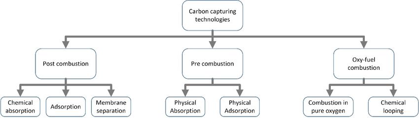
Sustainability 2021, 13, 10681                                                                                           2 of 30

                                 higher GHG emissions. Therefore, natural gas has become the most popular fossil fuel for
                                 building heating.
                                       Building energy retrofits reduce energy consumption and associated operational GHG
                                 emissions from the building heating process in existing buildings. Building energy retrofits
                                 can be categorized as minor retrofits, such as upgrading the building envelopes; major
                                 retrofits, such as upgrading heating system efficiency; and deep retrofits, such as upgrading
                                 the heating system with renewable energy technologies [5]. Among the different types
                                 of retrofits, “deep” retrofits can limit operational GHG emissions by reducing energy
                                 demands and using cleaner energy sources.
                                       Solar-thermal heating systems, ground-source heat pumps, and biomass energy sys-
                                 tems are the main renewable energy technologies that are used for building heating [6].
                                 However, these technologies are not commonly used in buildings due to various technical
                                 and economic limitations. Passive solar thermal systems are limited in their capacity to
                                 contribute towards building heating in the winter. Therefore, passive solar-thermal systems
                                 are not commonly used for building space heating in colder climates where the highest
                                 energy demands are in the winter [7]. Ground-source heat pumps can reduce energy
                                 demands considerably [8]. However, heat pumps require electricity for their operation. If
                                 electricity is generated using renewable energy, using ground-source heat pumps will sig-
                                 nificantly reduce operational GHG emissions [9]. Yet, around 66% of the world’s electricity
                                 is generated using fossil fuels [10]. Therefore, using heat pumps will not be a solution
                                 for regions where electricity is primarily generated using fossil fuel. Biomass systems
                                 are meant to be a cleaner alternative to the fossil fuel supply. However, biomass heating
                                 systems are not commonly used for building heating due to the considerable biomass
                                 storage requirements and the challenges of developing an efficient logistic system to supply
                                 the required biomass [11]. In addition to all of the above technical factors, significantly
                                 high investment costs are also a barrier to integrating renewable energy technologies [12].
                                       In addition to the above-mentioned energy efficiency and renewable energy interven-
                                 tions, carbon capture, utilization, and storage technology (CCUS) is becoming an emerging
                                 alternative for mitigating the emissions associated with fossil fuels. CCUS technology
                                 separates CO2 from combustion sources such as chemical industries and fossil fuel power
                                 plants. The captured CO2 is stored in geological formations or is utilized in usable prod-
                                 ucts [13]. This approach is commercially used in inherent CO2 separation applications
                                 such as in NG processing and chemical production, which produce high-density CO2 [14].
                                 Recently, the prospects of downsizing the existing carbon capture strategies to reduce
                                 GHG emissions from buildings have been considered. The potential of emission reduction
                                 without compromising building energy economics is the main motivation behind this
                                 strategy. Some pilot-scale carbon capture devices have been developed for use in NG
                                 building heating systems [15]. However, the lack of economic, environmental, and social
                                 assessments (triple bottom line of sustainability assessment) as well as a lack of feasibility
                                 assessment and research and development activities are critical challenges for the successful
                                 commercialization and market penetration of building-level carbon capture systems.
                                       Several studies reviewing the CCUS technology literature can be found. Rosa M. and
                                 Azapagic A. conducted a critical review on the life cycle environmental impacts of CCUS
                                 technologies [16]. González-Salazar reviewed recent developments in the carbon capture
                                 technologies used in gas power generation [17]. Asif M. et al. and Vega F. et al. reviewed
                                 the current status of the chemical absorption technologies used for carbon capture [18,19].
                                 These literature reviews identified challenges and prospects of implementing CCUS tech-
                                 nologies in the fossil fuel power generation sector and of scaling up the deployment of
                                 CCUS technologies. In addition, Hetti R. et al. conducted a literature review on integrating
                                 CCUS technologies into community-scale energy systems [20]. The authors considered
                                 the prospects of downsizing the CCUS technologies used in large-scale fossil fuel power
                                 generation plants into centralized community energy systems [20]. The study scope was
                                 limited to community-scale electricity generation plants and district energy systems [20].
                                 However, there is a lack of information on the prospects and challenges of implementing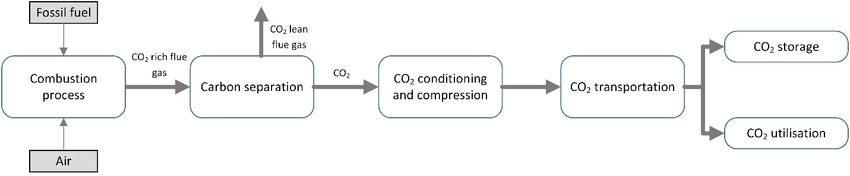
Sustainability 2021, 13, 10681                                                                                             3 of 30

                                   CCUS technologies in building-scale heating systems in those studies. Specifically, techni-
                                   cal requirements, environmental and socio-economic impacts, and the drivers and barriers
                                   of building-level CCUS technologies have yet to be explored.
                                         This paper aims to investigate the potential of reducing the GHG emissions of NG
                                   building heating systems by implementing carbon capturing, storage, and utilization
                                   (CCUS) technologies. This study critically reviews published articles on CCUS technologies
                                   used in fossil fuel power generation and discusses the possibility of adopting all of the
                                   possible carbon capturing process stages in the building context. This study consists of
                                   three main sections. The first section provides a brief overview of the CCUS technologies
                                   used in fossil fuel power generation. The second section discusses the technical adaptation
                                   of carbon capture in building-level applications. Finally, the sustainable implementation of
                                   carbon capture at the building level is discussed by considering environmental, economic,
                                   and social aspects. The compilation of the information found here is useful for researchers
                                   and innovators to study the technical feasibility and triple bottom line sustainability of
                                   implementing carbon capture at the building level.

                                   2. Materials and Methods
                                        Keyword searching in subject-specific databases such as “Compendex Engineering
                                   Village” and “ScienceDirect” was used to collect the relevant literature. The study used the
                                   keyword combinations of “carbon capture”, “storage”, utilization”, “building heating”,
                                   and “post-combustion” to search for studies from databases mentioned above. The study
                                   prioritized 51 journal articles published after 2005 from 13 high impact factor journals (with
                                   impact factors above 2.5). The selected journals and their impact factors are listed in the
                                   Table 1 shown below.

                                            Table 1. Primary sources of published literature.

                        Journal Paper                             Impact Factor (2018)               Number of Papers
        Renewable and Sustainable Energy Reviews                         10.556                              5
             Aerosol and Air Quality Research                             2.735                               1
                       Applied Energy                                     8.426                               8
               Applied Thermal Engineering                                4.026                               1
               Chemical Engineering Science                               3.372                               1
                           Energy                                         5.537                               1
           Energy Conversion and Management                               7.181                               3
                       Energy Policy                                       4.88                               2
                            Fuel                                          5.128                               2
      International Journal of Greenhouse Gas Control                     3.231                              15
               Journal of Cleaner Production                              6.395                               4
                 Journal of CO2 Utilization                               5.844                               2
                Journal of Membrane Science                               7.015                               2

                                        Apart from that, publications published prior to 2005 were used in cases where
                                   more recent information was unavailable. Furthermore, Canadian Government reports,
                                   conference proceedings, relevant websites, and other reports related to carbon capture and
                                   building heating were also considered.

                                   3. An Overview: Carbon Capture, Utilization, and Storage (CCUS) Technologies
                                         According to the International Energy Agency, 30 million tons of CO2 are captured
                                   annually by carbo capture facilities. Out of those 30 million tons, 90% is captured from
                                   oil and gas production industries, which produce high-density CO2 streams [21]. Tech-
                                   nologies for capturing high-density CO2 have been widely deployed and have reached
                                   technological maturity. However, most stationary combustion sources produce low concen-
                                   tration CO2, and the technologies used to capture CO2 from these sources are in the initial
                                   deployment stage.
Sustainability 2021, 13, x FOR PEER REVIEW 4 of 32
Technologies for capturing high-density CO2 have been widely deployed and have
Sustainability 2021, 13, 10681 reached technological maturity. However, most stationary combustion sources produce 4 of 30
low concentration CO2, and the technologies used to capture CO2 from these sources are
in the initial deployment stage.
The carbon capture
The carbon capturetechnologies
technologiesused usedfor forstationary
stationary combustion
combustion energy
energy sources
sources cancan
be
be classified as post-combustion, pre-combustion, and oxy-fuel
classified as post-combustion, pre-combustion, and oxy-fuel combustion technologies [22]. combustion technologies
[22]. This
This classification
classification is based
is based on the
on the combustion
combustion process
process and andgas gasextraction
extractionpoint.
point. Post-
Post-
combustion carbon capture technology is used to capture CO
combustion carbon capture technology is used to capture CO2 from flue gas after combus- 2 from flue gas after combus-
tion
tion isis completed
completed[23]. [23].ItItcancan
bebeusedused to capture
to capture CO2CO 2 from fossil fuel power plants [24]
from fossil fuel power plants [14,24,25],
process heaters, and combined heat and power plants used inused
[14,25], process heaters, and combined heat and power plants in chemical
chemical production
production facili-
facilities. This technology has been identified as the most practical
ties. This technology has been identified as the most practical carbon capture technology, carbon capture tech-
nology, as it can be implemented as a retrofit to existing
as it can be implemented as a retrofit to existing stationary combustion sources withoutstationary combustion sources
without
changingchanging the infrastructure
the infrastructure and theand the combustion
combustion methodmethod considerably
considerably [22,26,27].
[22,26,27]. Post-
Post-combustion
combustion carbon carbon
capturecapture is considered
is considered the most
the most mature
mature carboncarbon capture
capture technology
technology in
in
thethe power
power generation
generation sector
sector and and is the
is in in the early
early stages
stages of deployment
of deployment [28].
[28].
Pre-combustion technology is used to capture CO22 from from the the fuel
fuel before the combus-
tion process begins [22]. The pre-combustion capture
process begins [22]. The pre-combustion capture process is generally process is generally usedusedin fuel
in gas-
fuel
ification processes, where coal [22], biomass [29], or natural
gasification processes, where coal [22], biomass [29], or natural gas [25] is used as thegas [25] is used as the primary
fuel. It is fuel.
primary in theItearly
is instages
the earlyof deployment and commercializing
stages of deployment projects [28].
and commercializing In oxy-fuel
projects [28].
combustion, fuel is reacted
In oxy-fuel combustion, with
fuel pure O2with
is reacted dilutedpurewith O2 recirculated
diluted withflue gas. The oxygen
recirculated flue gas. is
separated
The oxygen from the air by from
is separated means theof air
theby cryogenic
means of separation
the cryogenicmethod [30]. However,
separation methodlarge-[30].
However,
scale large-scale
oxy-fuel carbon oxy-fuel carbon capture
capture facilities have not facilities have not been
been established due established due to
to the high energy
the high energy
requirements requirements
needed for the Oneeded for the
2 separation O2 separation [22,31].
[22,31].
Post-combustion and
Post-combustion andpre-combustion
pre-combustiontechnologies
technologiesrequire require carbon
carbon separation
separation methods
meth-
to separate
ods to separateCO2CO from gas. gas.
2 from Approaches
Approaches to separate
to separate CO2CO , such as absorption,
2, such as absorption, adsorption,
adsorp-
and membrane
tion, and membrane separation, are well
separation, areknown in the industry.
well known In contrast,
in the industry. the oxy-fuel
In contrast, method
the oxy-fuel
does notdoes
method require any specific
not require CO2 separation
any specific CO2 separation method, as theascombustion
method, the combustion products
productsare
only CO and water vapor. The water vapor can be removed
are only CO2 and water vapor. The water vapor can be removed through the condensation
2 through the condensation
of the
of the combustion
combustionproducts products[32]. [32].TheThe captured
captured COCO 2 has
2 has to beto stored
be stored or utilized
or utilized to stop
to stop CO2
CO
from from being released into the atmosphere. Moreover,
2 being released into the atmosphere. Moreover, it has to be compressed and liquefiedit has to be compressed and
liquefied after the capturing process depending
after the capturing process depending on the CO2 transportation, on the CO 2 transportation, storage,
storage, and utilization and
utilization
method method
[33]. Figure[33]. Figurethe
1 shows 1 shows
carbonthe carbonstorage,
capture, capture,and storage, and utilization
utilization process of process
post-
of post-combustion and pre-combustion
combustion and pre-combustion technologies. technologies.
Figure 1. Post-combustion carbon capture process.
process.
3.1. Carbon Separation Methods
The main modes of separation that are currently in practice are absorption, adsorp-
tion, chemical looping, membrane separation, hydrate-based separation, and cryogenic cryogenic
distillation. In
In the
the absorption
absorptionprocess,
process,the
theCO 2 2from
CO fromthe
theflue gas
flue is absorbed
gas is absorbedby by
a liquid so-
a liquid
lution called
solution an an
called absorbent
absorbent [34].[34].
Chemical
Chemicalabsorption and physical
absorption absorption
and physical are the
absorption main
are the
processes [31,34].
main processes In chemical
[31,34]. absorption,
In chemical CO2 reacts
absorption, with the
CO2 reacts chemical
with solventsolvent
the chemical and formsand
an intermediate
forms compound
an intermediate [35]. In[35].
compound physical absorption,
In physical the CO2the
absorption, bonds
CO2with thewith
bonds solvent
the
using Van der Waals forces in a liquid solution without any reaction [36].
solvent using Van der Waals forces in a liquid solution without any reaction [36]. Gener- Generally, the
bonds
ally, formed
the bondsbetween CO2 andCO
formed between the2 solvent
and thein chemical
solvent absorption
in chemical are stronger
absorption are than the
stronger
bondsthe
than formed
bondsinformed
physicalin absorption. Therefore,Therefore,
physical absorption. the CO2 absorption efficiencyefficiency
the CO2 absorption in chemical in
absorption is higher than that of physical absorption. Chemical absorption is more suitable
for capturing CO2 from flue gas with low pressure and a low CO2 concentration [35].
Chemical absorption is used in post-combustion technology, while the physical absorption
method is used in pre-combustion technology [37,38].Sustainability 2021, 13, x FOR PEER REVIEW 5 of 32
chemical absorption is higher than that of physical absorption. Chemical absorption is
Sustainability 2021, 13, 10681 5 of 30
more suitable for capturing CO2 from flue gas with low pressure and a low CO2 concen-
tration [35]. Chemical absorption is used in post-combustion technology, while the phys-
ical absorption method is used in pre-combustion technology [37,38].
In the adsorption
adsorption method,
method, the the substances
substances (adsorbate)
(adsorbate) adhere
adhere to to aa solid
solid surface
surface (ad-
(ad-
sorbent).
sorbent). TheThe adhered
adhered substances
substances can can bebe removed
removed later by changing the temperature or
pressure. The Theadsorption
adsorptionprocess processcancanbebe categorized
categorized as physisorption
as physisorption andandchemisorption.
chemisorp-
The
tion.adsorption
The adsorptionand desorption
and desorptionprocesses are performed
processes using using
are performed three main
three methods:
main methods:pres-
sure swing
pressure adsorption,
swing adsorption, vacuum swing
vacuum adsorption,
swing adsorption, and and
temperature
temperature swing absorption.
swing absorp-
Apart from from
tion. Apart that, electric swingswing
that, electric adsorption and pressure
adsorption and pressureand temperature
and temperature hybrid pro-
hybrid
processes
cesses are also
are also usedused foradsorption
for the the adsorption process,
process, which which are considered
are considered to be to be advanced
advanced tech-
technologies
nologies [39].[39]. Furthermore,
Furthermore, the adsorption
the adsorption method method
can becan be used
used for post-combustion
for post-combustion cap-
capture
ture [16].[16].
Membrane separation
separationisisaanovelnoveltechnology
technologycompared
compared toto
the other
the otherseparation
separation methods
meth-
discussed above. This carbon separation method is considered to
ods discussed above. This carbon separation method is considered to be a flexible method, be a flexible method, as
it can be used in post- and pre-combustion technologies [40]. In
as it can be used in post- and pre-combustion technologies [40]. In membrane technolo- membrane technologies,
most most
gies, of theofenergy is consumed
the energy in order
is consumed to develop
in order the required
to develop pressure
the required difference
pressure across
difference
the membranes
across the membranes[41]. This
[41].technology
This technologyis veryis economical
very economical whenwhenhigh-purity
high-purityCO2 COis not
2 is
required.
not Post-combustion
required. Post-combustion technology requires
technology membranes
requires with high
membranes selectivity,
with as the COas2
high selectivity,
concentration
the of the flue
CO2 concentration ofgas
theisflue
very low
gas is [40].
very Membrane systems that
low [40]. Membrane have high
systems selectivity
that have high
consume more energy and have significantly higher costs compared
selectivity consume more energy and have significantly higher costs compared to low- to low-selectivity
membranes.
selectivity Therefore, Therefore,
membranes. it is challenging to implement
it is challenging membrane membrane
to implement systems commercially
systems com- in
post-combustion carbon capture systems [42], leading to membrane
mercially in post-combustion carbon capture systems [42], leading to membrane separa- separation methods
still methods
tion only being implemented
still at lab scale. at
only being implemented Figure 2 shows
lab scale. Figure the2 shows
classification of carbon
the classification
capture
of carbon technologies.
capture technologies.
Figure 2. Classification
Figure 2. Classification of
of carbon capture technologies.
carbon capture technologies.
3.2. CO
CO22 Transportation
Transportation
The captured CO22 should
should be be transported
transported from the carbon sources to specific storage
locations. InIn the USA, several million tons of CO22 are transported annually for enhanced
oil recovery.
recovery. The transportation methods methods should
should be capable of transporting CO22 efficiently efficiently
with little leakage. More
More importantly,
importantly, the transportation methods should be economically
viable [43].
[43].The
TheCO CO2 can
2 canbebetransported
transported using pipelines,
using tanker
pipelines, trucks,
tanker ships,
trucks, and railroads
ships, and rail-
[44].
roadsPipeline systems
[44]. Pipeline are the
systems aremost efficient
the most and and
efficient viable method
viable methodused to transport
used to transport COCO2 on
2
aonlarge scale.
a large Tanker
scale. Tanker trucks
trucksareare
used
usedtototransport
transportCO CO2 2ininthe
theshort
shortterm
term and
and over short
Moreover, transporting CO22 using tanker trucks and railroads is overlooked in
distances. Moreover,
the literature.
Pipeline transportation
Pipeline transportationcan canbebeused
usedforfor both
both onshore
onshore and and offshore
offshore COCO 2 transporta-
2 transportation
tion [45].
[45]. However,
However, pipelines
pipelines are not
are not tested
tested for for offshore
offshore COCO 2 transportation
2 transportation [46].
[46]. Fixed
Fixed or
or towed
towed pipes
pipes areare
thethe mostcommercially
most commerciallyviable viablemethod
methodtototransport
transportCO CO2 2toto the
the ocean.
ocean.
Recompression stations
Recompression stations areare used to reduce the pressure head (i.e., compensate for the
pressure head).
head).Pipeline
Pipelinetransportation
transportation facilities
facilities consists
consists of aofCO
a CO 2 conditioning
2 conditioning facility
facility that
that conducts CO2 compression and further separation from water vapor and other gases.
Generally, CO2 is compressed to 100–150 bar in order to transport the CO2 through pipe
lines [45]. In some cases, CO2 is compressed to the liquid state so that it can be pumped.
This method reduces the energy requirement for transporting CO2 through pipelines [45].Sustainability 2021, 13, 10681 6 of 30
Waterborne transport is another method that can be used to transport CO2 over very
large distances [47]. Ships and other types of watercrafts can be used to transport CO2
under conditions where pipelines are not viable. The CO2 should be in liquid form in
order to reduce the transport volume when using ships [48]. In contrast to CO2 transport
using pipelines, ship transportation is a discrete transportation mode [48]. Therefore,
ship transportation requires buffer storage or temporary storage [49,50]. The CO2 is
transferred from the temporary storage site to the ship loading facilities. Ship transport can
be used to transport CO2 from the loading facilities to offshore or onshore storage facilities.
Furthermore, studies are being conducted where CO2 is injected directly into the ocean
using ships [50].
3.3. Carbon Storage
The captured CO2 can be stored in geological storage and in offshore storage and
can be converted into mineral carbonates [16]. Depleted oil or natural gas reservoirs [51]
and saline aquifers are geological CO2 storages. Furthermore, un-mineable coal beds are
also considered to be geological CO2 storage. Generally, CO2 is injected into geological
formations at depths higher than 800 m [16]. Geological storage should consist of a porous
rock and cap rock to store CO2 . The porous rock acts as the storage medium where CO2 is
stored. The caprock is used to avoid CO2 leakage from the storage. The CO2 is trapped in
the storage site by means of physical trapping, dissolution in saltwater, and absorption into
coal or organic-rich shale replacing methane (CH4 ) and other gases. The dissolved CO2
can be reacted with rocks and minerals and can be stored permanently. The CO2 can be
stored as compressed gas, liquid CO2 , or in the supercritical phase. This choice depends on
the storage conditions [16]. Furthermore, storing CO2 in geological formations has become
a promising option due to the oil and gas industry’s expertise in geological formations [16].
The ocean is a natural carbon sink that currently absorbs 7 GtCO2 per year [47]. Apart
from that, CO2 can be intentionally injected into the sea using the ocean storage method [52].
Here, CO2 is injected into the water column of the ocean or the seafloor. It is possible to
inject CO2 into the sea in the form of gases, liquids, solids, and hydrates, depending on the
injection technology. The CO2 is dissolved in the ocean regardless of the form it is injected
in. It has to be injected at a depth less of than 500 m to release CO2 as gas. When CO2
is released below 500 m and above 2500 m, it is released as a liquid and moves upward
(towards the surface of the water) while dissolving. If the release depth is higher than
2500 m, the CO2 is released as a liquid and moves down (towards the ocean floor). It is
possible for the CO2 to be dissolved completely before it arrives at the ocean surface or
to remain as a CO2 lake at the ocean floor until it is completely dissolved. Deep ocean
storage is still in the research phase, and there are no pilot-scale projects that are currently
ongoing [47].
3.4. CO2 Utilization
There are various methods of using CO2 in industry. The carbon capture can be used
as a chemical feedstock in industries and can used in applications such as synthesizing
methanol and other types of polymers [53]. Furthermore, it can be used directly as a carbon-
ating agent, preservative, and solvent in the food and beverage industry [16,54]. Moreover,
CO2 is used as a working fluid in refrigeration cycles [55]. In addition, CO2 is used in many
industries, such as steel manufacturing, power generation, metalworking and welding,
and pneumatics [54].
Enhanced oil recovery (EOR) is also a fuel production method with an increasing
demand for CO2 [16]. In the EOR process, CO2 is injected with other chemicals into
an underground oil reservoir in order to remove the oil trapped in the rocks [56]. This
method can extract more than 30–60% of the trapped oil [16]. Most CO2 is removed along
with the oil, and the oil needs to be treated before use. However, some of the CO2 may be
released into the atmosphere during this treatment process [16].Enhanced oil recovery (EOR) is also a fuel production method with an increasing
demand for CO2 [16]. In the EOR process, CO2 is injected with other chemicals into an
underground oil reservoir in order to remove the oil trapped in the rocks [56]. This
Sustainability 2021, 13, 10681
method can extract more than 30–60% of the trapped oil [16]. Most CO2 is removed 7along of 30
with the oil, and the oil needs to be treated before use. However, some of the CO2 may be
released into the atmosphere during this treatment process [16].
In addition,
In addition, other
other industrial
industrial uses useshave
havebeen beenintroduced
introduced inin recent
recenttimes.
times.Mineral
Mineralcar-
bonation is considered to be a storage method in few studies [16,57,58],
carbonation is considered to be a storage method in few studies [16,57,58], while others while others con-
sider it to
consider it be a utilization
to be a utilization method
method [16,54]. In this
[16,54]. process,
In this process,COCO 2 is reacted with minerals
2 is reacted with min-
such such
erals as Wollastonite
as Wollastoniteand Serpentine
and Serpentine and formandmineral carbonates
form mineral [57]. Therefore,
carbonates CO2 can
[57]. Therefore,
be 2permanently
CO stored within
can be permanently storedawithin
chemical. On the other
a chemical. On the hand,
other this method
hand, has a higher
this method has
capacity than all other fossil reserves, as magnesium and calcium-rich
a higher capacity than all other fossil reserves, as magnesium and calcium-rich minerals minerals can be
efficiently mined [58]. However, this method requires input energy,
can be efficiently mined [58]. However, this method requires input energy, thus in directly thus in directly con-
tributing to additional
contributing to additional GHG GHG emissions.
emissions.
Bonaventura et
Bonaventura etal.
al.(2017)
(2017)described
describedaanovel novelmethod
methodofofcapturing
capturingCO CO2 .2.This
Thisprocess
process
producesNaHCO
produces NaHCO33 as as aaby-product
by-productduring duringthethecarbon
carboncapture
captureprocess
process[26].
[26].This
Thisprocess
process
usesTrona
uses Tronaas asthe
thechemical
chemicalsolvent,
solvent,whichwhichisisaalow-cost
low-costmineral
mineralused usedtotoproduce
produceNa Na2 CO
2CO 33..
Theprocess
The processcan canbebecontrolled
controlled sosothatthat only
only a fraction
a fraction of the
of the COCO2 is is utilized.
utilized.
2 The The other
other frac-
fraction
can
tionbe stored
can or utilized
be stored in another
or utilized in anothermethod. It is also
method. possible
It is also to use
possible ammonia
to use ammonia (NH(NH
3 ) to3)
capture
to captureCOCO2 while
2 whileproducing
producing ammonium
ammonium salts
salts[59]. InInthis
[59]. thisprocess,
process,the theammonium
ammoniumsalts salts
have
have totobebeseparated
separatedfrom fromthe thesolvent
solventusing
usingfiltration
filtrationororsedimentation.
sedimentation.The Theseparated
separated
ammonium
ammoniumcan canbebeused
usedin inthe
theagriculture
agricultureindustry
industryas asaafertilizer
fertilizeringredient
ingredient[60].[60].Utilizing
Utilizing
CO
CO22 in
inanother
anotherproduct
productmay may help
help to to
avoid energy
avoid energy consumption
consumption andand GHGGHG emissions related
emissions re-
to the production of that product.
lated to the production of that product.
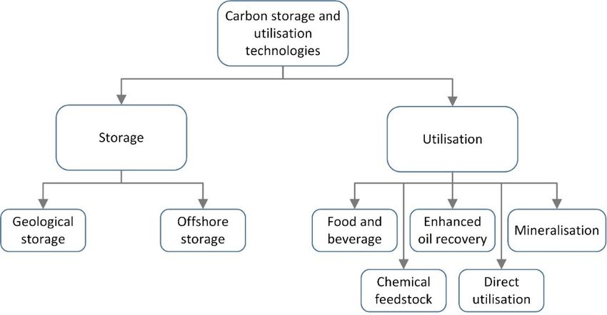
AA summary
summary of of the
thecarbon
carbonstorage
storageandandutilization
utilizationapplications
applicationsdiscussed
discussed above
aboveisis
shown below in Figure
shown below in Figure 3. 3.
Figure3.3.Classification
Figure Classificationof
ofcarbon
carbonstorage
storageand
andutilization
utilizationmethods.
methods.
4.4.Adoption
Adoptionof ofthe
theCCUS
CCUSValueValueChain
Chainfor forBuilding
BuildingScale
Scale
Liyanage
Liyanage [61,62] and Pokhrel [63] mentioned a carbon technology
[61,62] and Pokhrel [63] mentioned a carbon technology that
that can
can be
be inte-
inte-
grated
gratedinto
intobuilding
buildingheating
heatingsystems.
systems.BasedBasedon onthe
theliterature
literaturereview,
review,this
thistechnology
technologywaswas
the
theonly
onlyone
onethat was
that found
was found to be
to used in building-scale
be used applications.
in building-scale The system
applications. uses solid
The system uses
potassium hydroxide
solid potassium (KOH) (KOH)
hydroxide to capture the CO2the
to capture from
COthe exhaust
2 from gas emitted
the exhaust gas from natural
emitted from
gas building heating systems. The reaction between KOH and CO produces
natural gas building heating systems. The reaction between KOH and CO2 produces po-
2 potassium
carbonate (K2 CO3 )(K
tassium carbonate as2CO
a by-product. The chemical reaction is given in Equation (1) below.
3) as a by-product. The chemical reaction is given in Equation (1) be-
The by-product is widely used for pharmaceutical
low. The by-product is widely used for pharmaceutical purposes, soapsoap
purposes, production, andand
production, as
aaschemical feedstock in many industries
a chemical feedstock in many industries [63]. [63].
2KOH (s) + CO2 ( g) → K2 CO3 (s) + H2 O(l ), (1)
In addition, the chemical reaction given in Equation (1) is exothermic and therefore
generates heat during the carbon capture process. The carbon capture system recovers heat
from the chemical reaction and the waste heat from the flue gas. The recovered heat is
transferred into the domestic hot water system. This carbon capture system is currently
available commercially and is only used in commercial buildings. Liyanage [61,62] con-Sustainability 2021, 13, 10681 8 of 30
ducted experimentation on the above-mentioned carbon capture system and found that its
average carbon recovery rate is 13%. In addition, the average heat transfer rate from the
heat recovery system to the domestic hot water system is 26 kJ/l. Currently, the system can
contain 200 kg of KOH per month [61,62]. Hereafter, this technology will be referred to as
KOH-based building-level carbon capturing technology.
It is also important to consider the adoptability of the other CCUS technologies used in
the power generation sector at the building level. The CCUS value chain consists of carbon
capture, CO2 transportation, and CO2 storage or utilization. All of the processes involved
in CCUS technology must be successfully adapted in order for carbon capture technology to
be used at a building scale. Among the three carbon capture technologies discussed about,
pre-combustion capture technology cannot be used with natural gas building heating
furnaces, as there is no intermediate CO2 generation during the combustion process. The
oxy-fuel combustion method needs an additional oxygen supply and a different combustion
system and therefore is not considered in this review. Only post-combustion technology
shows promise in investigating the potential of adopting the CCUS value chain at the
building scale.
4.1. Operational Conditions and CO2 Output of Carbon Separation Technologies
Chemical absorption, adsorption, and membrane separation are the separation tech-
nologies that are used in post-combustion carbon capture technology, as explained in
Section 3.1. Flue gas properties, including temperature, pressure, and CO2 concentra-
tion, are considered important parameters when selecting suitable carbon separation
technologies [64]. Table 2 shows the operational conditions of the above-mentioned carbon
separating technologies. In addition, Table 2 shows the optimum CO2 composition and
the CO2 purity after the separation process in the chemical absorption, adsorption, and
membrane separation methods [65].
Table 2. Operating conditions and outputs of carbon separation technologies [34,65–68].
Carbon Separation Method Operating Temperature CO2 Composition CO2 Purity CO2 Capture %
Chemical absorption using
45–50 ◦ C >5% >95% 80–95%
Methyl Ethanolamine (MEA)
Chemical absorption using Econamine 80–120 ◦C >5% >95% 80–95%
Chemical absorption using 2n ◦C
35–40 >5% >95% 80–95%
Methyl Diethanolamine (MDEA)
Chemical adsorption PSR 50 ◦C >10% 75–90% 80–95%
Physical adsorption PSA 50–100 ◦ C >10% 75–90% 80–95%
Membrane separation - >15% 80–95% 60–80%
The CO2 composition of flue gas from a natural gas combustion systems varies from 7%
to 10% [50]. Therefore, chemical absorption technology must be used with building heating
systems without making any modifications to the boiler system. Membrane separation and
adsorption processes cannot be used directly with natural gas building heating systems.
The optimum CO2 composition in membrane separation is higher than that found in the
flue gas in natural gas heating systems [40]. However, recent studies indicate that the
CO2 composition of the flue gas can be increased by recirculating the flue gas through the
combustion system [50]. This procedure is used in NGCC combustion systems, as the CO2
composition of flue gas is 3–4% [50]. The same procedure can be used in building heating
systems after some modifications to the combustion process.
The temperature of the flue gas reduces with the increasing efficiency of the heating
system. Annual fuel utilization efficiency (AFUE) categorizes building heating systems
based on their efficiency. A standard efficient building has the lowest possible AFUE, which
is 78–80%, and the flue gas temperature in these buildings is approximately 232 ◦ C [69].
Mid-efficiency furnaces are widely used in buildings, and the efficiency can reach 83% with
a flue gas temperature of 149 ◦ C [69]. Therefore, flue gas must be cooled in both standardSustainability 2021, 13, 10681 9 of 30
and mid-efficiency furnaces. High-efficiency condensing heating systems emit flue gas at
a much lower temperature, approximately 50 ◦ C [69]. This indicates that highly efficient
furnaces can be used without cooling systems in most of the carbon separation technologies
shown in Table 2.
4.2. Energy Consumption of the Carbon Separation Process
The carbon capture process requires energy for its operation. Chemical absorption
technology requires thermal energy for solvent regeneration. In addition, electricity is
required for the operation of auxiliary equipment such as pumps and compressors. Table 3
shows the energy consumption of the chemical absorption method with different types
of solvents.
Table 3. Energy consumption of chemical absorption technology [70–74].
Separation Process Desorption Energy Auxiliary Energy
Commercial Level Solvents
Chemical absorption with MEA 3.53 GJth /tCO2 0.0432 GJe /tCO2
Chemical absorption Econmaine FG+ 3.18 GJth /tCO2 -
Chemical absorption KS-1 3.08 GJth /tCO2 -
Chemical absorption KS-2 3.0 GJth /tCO2 -
Chemical absorption CANSOLV 2.33 GJth /tCO2 -
Chemical absorption H3 2.8 GJth /tCO2 -
Chemical absorption with UNO MK3 2.24 GJth /tCO2 0.0612 GJe /tCO2
In the chemical absorption method, the required energy has to be supplied as heat
through steam. The temperature of the steam should be in a range from 100 ◦ C to
140 ◦ C [75]. Generally, the steam is extracted from steam turbines in power plants that are
integrated with carbon capture systems. Therefore, there is a possibility of using thermal
energy from standard-efficiency furnaces, as the temperature of the flue gas from these
furnaces is 232 ◦ C. In addition, using the thermal energy from low efficiency furnaces
may require separate cooling systems to reduce the flue gas temperature. Medium- and
high-efficiency furnaces must be modified to extract thermal energy, as the flue gas temper-
ature is low. However, these furnaces might reduce the heat generation of the furnace. As
a solution, the required thermal energy can be supplied using electric heaters. Some studies
have been conducted on integrating solar energy systems for carbon capture systems
to reduce the regeneration energy requirement from the power plant [75,76]. The same
procedure can be applied to building-level heating systems that have been integrated with
carbon capture systems to minimize fuel consumption. Furthermore, chemical absorption
technology requires energy to operate compressors, pumps, condensers, and re-boilers,
which are the auxiliary components of carbon capture systems.
Adsorption and membrane separation methods do not need thermal energy for their
operation. Instead, these technologies require electricity for the compression, vacuum
generation, and running of the auxiliary components. The post-combustion technology
requires membranes with high selectivity, as the CO2 concentration of the flue gas is
very low [40]. Membrane systems with high selectivity consume more energy and are
significantly more costly than low-selectivity membranes. Therefore, it is challenging
to implement the membrane systems in post-combustion carbon capture systems com-
mercially [38], and these systems are not commonly used commercially in natural gas
power plants. Table 4 shows the energy consumption of adsorption and membrane separa-
tion technologies.Sustainability 2021, 13, 10681 10 of 30
Table 4. Energy consumption of adsorption and membrane separation technologies [71,72].
Separation Process Energy Requirement
VPSA 2.140 GJE /tCO2
PSA 2.3–2.8 GJE /tCO2
TSA 6.12–6.46 GJE /tCO2
Membrane separation POL-POL 0.5–6 GJE /tCO2
4.3. Operational Parameters of Carbon Separation Technologies
A. Brunetti et al. investigated the major operational parameters that affect the effi-
ciency of carbon capturing systems [74]. The authors mentioned that operational flexibility,
turndown, and reliability are important parameters when designing carbon capture sys-
tems. The definitions of the above operational parameters are shown below.
• Operational flexibility: The ability of the system to operate in variable gas composi-
tions [65];
• Turndown: The ability of the system to operate under gas flow rates that are less than
the design flow rates [65];
• Reliability: The ability to operate continuously without unscheduled shutdown [65];
• Adaptability: The time required to adapt the carbon capture system for the changes in
the inflow properties [65].
Brunetti et al. showed that membrane systems are highly flexible when the CO2
concentration is higher than 20% [74]. The flexibility of membrane systems is reduced
dramatically when the CO2 concentration is less than 20%. As a result of the composition
changes, the CO2 recovery rate and the purity of CO2 are reduced. The adsorption method
is also considered to be a highly flexible carbon capture technology. The absorption systems
are moderately flexible compared to the membrane systems. In addition, the absorption
systems require changes in the liquid flow rate when the gas composition changes [77].
The liquid flow rate is limited by the size of the systems and thus restricts the flexibility of
the absorption system. This indicates that the absorption systems must be oversized when
the systems are subjected to higher gas composition variations. Brunetti et al. showed that
membrane systems are highly flexible when the CO2 concentration is higher than 20% [74].
The flexibility of membrane systems is reduced dramatically when the CO2 concentration
is less than 20%. As a result of these composition changes, the CO2 recovery rate and the
purity of CO2 are reduced. The adsorption method is also considered to be a highly flexible
carbon capture technology. The absorption systems are moderately flexible compared to
membrane systems. In addition, absorption systems require changes in the liquid flow rate
when the gas composition is changed [77]. The liquid flow rate is limited by the size of
the systems and thus restricts the flexibility of the absorption system. This indicates that
the absorption systems must be oversized when the systems are subjected to higher gas
composition variations.
Most power generation plants are operated with a steady combustion rate. In contrast,
the thermal energy load of the building changes considerably over time. As a result, the
fossil fuel combustion rate and the CO2 flow rate change. Therefore, carbon capture systems
must be able to maintain their performance regardless of the variations in the gas flow rates.
Therefore, the turndown capability of carbon capture systems is important when used in
the building context. A. Brunetti et al. showed that membrane systems can maintain the
purity of the CO2 stream even at 10% of the design flow [74]. Therefore, membrane systems
can be defined as systems with a higher turndown capability. Absorption technology
can maintain its CO2 recovery and CO2 purity downstream at 30 to 100% of its design
flow. Although chemical absorption technology can maintain purity even when the flow is
less than 30% of its design flow, CO2 recovery can be reduced considerably. Adsorption
technology can also deliver the expected CO2 recovery and CO2 purity, even at 30% of its
design flow [65,78].Sustainability 2021, 13, 10681 11 of 30
Although operational flexibility and turndown measure the resilience of carbon cap-
ture systems for variations in the flow and composition, it is essential to investigate how
much time is needed for system adaptation. Building heating systems especially are sub-
jected to frequent load changes. Membrane separation systems can adapt to such variations
instantaneously, while absorption and adsorption technologies can adapt within 5–15 min.
A building environment has less technical experts than the industrial environment
does, which is where carbon capture systems are currently installed. Therefore, carbon
capture systems must be more reliable. Membrane separation is known to be extremely
reliable, as it has less control components [74]. The absorption method is considered to
be moderately reliable [65,74]. More specifically, the equipment used to reduce chemical
degradation can cause unscheduled shutdowns and may require frequency maintenance.
The adsorption method is also moderately reliable [65] compared to the membrane separa-
tion method. A summary of the carbon separation technologies that are currently being
adopted is given in Table 5.
Table 5. Summary of carbon separation technologies adopted at building level.
Suitability of the Carbon
Technical Criteria Chemical Absorption Adsorption Membrane Separation
Capture System
Operational Conditions
Gas cooling is required for
Gas cooling is required for Gas cooling is required for standard- and
standard- and standard- and medium-efficiency Absorption, adsorption,
Operating temperature medium-efficiency furnaces medium-efficiency furnaces furnaces and membrane separation
Gas cooling is not required Gas cooling is not required Gas cooling is not required have the same suitability
for high-efficiency furnaces for high-efficiency furnaces for high-efficiency
furnaces
Exhaust gas recirculation is Exhaust gas recirculation
Exhaust gas recirculation Absorption method is
CO2 composition not needed is needed
is needed more suitable
Best option Moderate option
Carbon capture performance
Captured CO2 can be used Captured CO2 can be used Captured CO2 can be used
Absorption method is
CO2 purity with any utilization and with few utilization and few utilization and
more suitable
storage method storage methods storage methods
Absorption method is
CO2 capture rate Has higher CO2 recovery Has moderate CO2 recovery Has low CO2 recovery
more suitable
Thermal energy is
Only electricity is needed.
required—The furnace can
Only electricity is needed. High energy requirement Absorption method is
Energy requirement be modified or can use
High energy requirement as the CO2 concentration more suitable
electrical heating
is low
Medium energy requirement
Operational parameters
Low flexibility Adsorption method is
Operational flexibility Medium flexibility High flexibility
(For CO2 < 20%) more suitable
Can maintain CO2 recovery
Can maintain CO2
and purity down to 30% Can maintain CO2 recovery Membrane separation
Turndown recovery and purity down
Can maintain CO2 purity and purity down to 30% method is more suitable
to 10%
below 30%
Membrane separation is
Reliability Medium reliability Medium reliability High reliability
more suitable
Membrane separation is
Adaptability Within 5–15 min Within 5–15 min Instantaneous
more suitable
Membrane separation technology shows higher performance with regard to opera-
tional flexibility, turndown, adaptability, and reliability compared to other technologies.
However, membrane separation requires a higher percentage of CO2 in the inflow (over
20%), which is considerably higher than that of the flue gas composition (less than 10%)
of natural gas building heating systems. Although flue gas recirculation is a possible
solution [79,80], it may need considerable modifications in the existing heating systems
that require further research. Adsorption technology has a lower performance compared
to all of the above factors. It performs well in terms of operational flexibility compared to
absorption technology, although absorption technology requires less energy. However, ad-
sorption technology may also require flue gas recirculation since it operates at a higher CO2Sustainability 2021, 13, 10681 12 of 30
percentage (>10%). The absorption technology has moderate performance and considers
all of the factors while working at a very low CO2 concentration (>5%). Thus, absorption
technology may be more applicable for natural gas furnaces, as it does not require any
modifications to the building heating system.
4.4. Transportation of CO2 and By-Products in Building Scale
The CO2 utilization and storage step can be a critical phase in building-level carbon-
capturing that defines the economic viability of the whole process. It is necessary to
transport CO2 over very long distances so that it can be stored within geological storage
sites, especially in Canada, where geological carbon storage is widely dispersed. Pipeline
transportation is the only commercially available method to transport CO2 over long
distances [81]. However, carbon transportation using pipelines from individual build-
ings would not be economically viable. Considerable capital investment is required in
developing such infrastructure. Middleton and Bielicki (2009) showed that pipeline trans-
portation costs would be extremely high for low CO2 flow rates [82]. Moreover, CO2 needs
to be highly compressed and conditioned for transportation, which increases the costs
for small-scale applications considerably. Therefore, CO2 transport using pipelines and
storage within geological storage sites would not be economically viable for small-scale
applications such as building heating systems.
Road transportation is a less attractive option in large-scale CO2 transportation appli-
cations. Road transportation costs twice as much as pipeline transportation in large-scale
carbon capture and storage projects [83]. However, tanker trucks are used to transport
CO2 from CO2 distribution terminals to customers for carbon utilization purposes [83].
Generally, CO2 should be in liquid form when being transported by tanker trucks to maxi-
mize transportation capacity. Therefore, compression and refrigeration systems must be
integrated into carbon capture systems. In addition, intermediate storage systems must be
implemented in buildings where CO2 is stored. When CO2 is converted into a by-product
during the carbon capture process [26,59], the by-products must be transported instead
of the CO2 gas. This reduces the space requirement as well as the energy requirement for
CO2 compression and liquefaction. However, this process requires the frequent loading
and unloading of chemicals. Therefore, the public acceptance of utilizing carbon during
the separation process would be questionable.
Buildings in colder climatic regions produce significant amounts of CO2 emissions due
to the higher thermal energy requirements. For example, an average residential building in
Canada that uses a NG heating system emits approximately 6 tons of CO2 per year [84].
Furthermore, most of these emissions are generated during the winter season and may
exceed 1 ton of CO2 per month for an average residence. Therefore, the carbon capture
percentage is mostly limited by material handling and transporting capacity despite the
higher CO2 capture efficiency of modern carbon capture technologies. Therefore, the
viability of building-level carbon capture systems mainly depends on efficient CO2 and
by-product transporting methods.
4.5. Technical Drivers and Barriers
The above review revealed that chemical absorption technology is suitable for opera-
tion in building-level heating systems based on flue gas properties without necessitating
substantial changes to the combustion system. However, the chemical absorption method
requires 5–15 min to adapt to the changes in flue gas rates. In addition, it only has moderate
reliability. Therefore, chemical absorption technology may require substantial R&D efforts
to improve the control mechanisms and reliability in order to integrated with building-level
heating systems. Membrane separation, which is more favorable for building operations
under most criteria, requires flue gas circulation due to the lower CO2 concentrations.
Therefore, heating systems may require considerable modifications in order to be used with
membrane separation technologies. In addition, buildings have limited space compared
to power generation plants. Therefore, one of the main barriers to implementation inrequires 5–15 min to adapt to the changes in flue gas rates. In addition, it only has moder-
ate reliability. Therefore, chemical absorption technology may require substantial R&D
efforts to improve the control mechanisms and reliability in order to integrated with
building-level heating systems. Membrane separation, which is more favorable for build-
ing operations under most criteria, requires flue gas circulation due to the lower CO2 con-
Sustainability 2021, 13, 10681 13 of 30
centrations. Therefore, heating systems may require considerable modifications in order
to be used with membrane separation technologies. In addition, buildings have limited
space compared to power generation plants. Therefore, one of the main barriers to imple-
mentation in buildings
buildings is spacelimitations.
is space limitationsSpecifically,
.Specifically, chemical
chemical absorption
absorption requires
requires taller columns that
taller columns that may not be feasible for installation in buildings [85], while membrane
may not be feasible for installation in buildings [85], while membrane separation may need
separation mayaneed largeaarea
large area [86].
[86].
The transportation of the capturedofCO
The transportation 2 or
the by-products
captured CO2 or is by-products
also one of the mainone
is also chal-
of the main chal-
lenges. Although pipeline
lenges. transportation
Although is commonly used
pipeline transportation in large-scale
is commonly used infacilities, using
large-scale facilities, using it
it at the building scale may not be practical due to large infrastructure requirements.
at the building scale may not be practical due to large infrastructure requirements. Road Road
transportation transportation
would be the would most practical
be the mostmethod formethod
practical building-level applications
for building-level alt-
applications although
hough it is a discrete mode ofmode
it is a discrete transportation [47]. Road
of transportation [47].transportation requires
Road transportation intermit-
requires intermittent CO2
tent CO2 storage in buildings,
storage whichwhich
in buildings, may require considerable
may require considerablespace.space.
In addition, the cap-
In addition, the captured CO2
tured CO2 mustmust be liquefied to betostored
be liquefied andand
be stored transported,
transported, which requires
which a considerable
requires a considerable amount of
amount of energy. Therefore,
energy. the potential
Therefore, for CO
the potential for2 reduction
CO2 reduction is restricted by theby
is restricted available
the available space in
the building
space in the building whenroad
when using usingtransportation.
road transportation.
FiguresFigures
4 and 5 4show
and 5possible
show possible
path- pathways to
ways to implementimplement building-level
building-level carbon carbon
capturecapture technologies
technologies that werethat were identified
identified based based on the
on the literatureliterature
review. review.
Solvent Electricity
Fuel
make-up grid
Thermal energy
Natural gas heating CO2 gas Compression and CO2 tank
Carbon capture Transportation
system Rich Flue gas temporary storage
Lean Flue gas
nability 2021, 13, x FOR PEER REVIEW 14 of 32
CO2 utilization
To the atmosphere
Figure 4. The proposed
Figure building-level
4. The carbon capture
proposed building-level process
carbon that process
capture separates COseparates
that 2 from flue
COgas (Ex:flue
2 from MEA-based
gas (Ex: chemical
absorption). MEA-based chemical absorption).
Chemical Electricity
Fuel
addition grid
Natural gas heating Rich Flue gas Carbon capture and By-products
Transportation
system utilization
Lean Flue gas
By-products
To the atmosphere Chemical industry
Figure 5. TheFigure
carbon5.capture processcapture
The carbon that converts COthat
process 2 intoconverts
a by-product
CO2(KOH-based building-level
into a by-product carbon building-
(KOH-based capture technology).
level carbon capture technology).
5. Implementation of Carbon Capture, Storage, and Utilization at Building Level
5. ImplementationThis of Carbon
study hasCapture,
revealedStorage, and Utilization
that integrating at Building
carbon capture Level when considering
has potential
thehas
This study technical
revealedaspects. However,
that integrating an increase
carbon captureinhas
energy demand,
potential whenemissions
consid- during the
operation,
ering the technical and
aspects. the production
However, of theinraw
an increase material
energy demand,required for theduring
emissions carbonthecapture process
may cause significant environmental impacts in the life cycle of
operation, and the production of the raw material required for the carbon capture process the carbon capture process.
may cause significant environmental impacts in the life cycle of the carbon capture pro- burdens by
Furthermore, the carbon capture process also carries substantial economic
increasing
cess. Furthermore, energy,
the carbon material,
capture transportation
process also carriescosts. In addition,
substantial the carbon
economic capture process
burdens
by increasing may
energy,increase the transportation
material, maintenance work costs. required in building
In addition, the carbonheating
capture systems,
pro- which can
reduce
cess may increase thethe acceptability
maintenance of implementing
work carbon capture
required in building heating to the building
systems, whichowners.
can Therefore,
it is necessary to consider the environmental impacts, economic
reduce the acceptability of implementing carbon capture to the building owners. There- costs and benefits, and
fore, it is necessary to consider the environmental impacts, economic costs and benefits,
and social acceptance of adapting the carbon capture value chain to building-level heating
systems successfully.You can also read