ELECTRICITY STORAGE SYSTEMS: APPLICATIONS AND BUSINESS CASES - CANADIAN ENERGY RESEARCH INSTITUTE
←
→
Page content transcription
If your browser does not render page correctly, please read the page content below
Study No. 180
                                                                       June 2019

CANADIAN
ENERGY         ELECTRICITY STORAGE SYSTEMS:
RESEARCH
INSTITUTE
               APPLICATIONS AND BUSINESS CASES

      Canadian Energy Research Institute | Relevant • Independent • Objective
Electricity Storage Systems: Applications and Business Cases                 i

                                    ELECTRICITY STORAGE SYSTEMS:
                                   APPLICATIONS AND BUSINESS CASES

                                                                     June 2019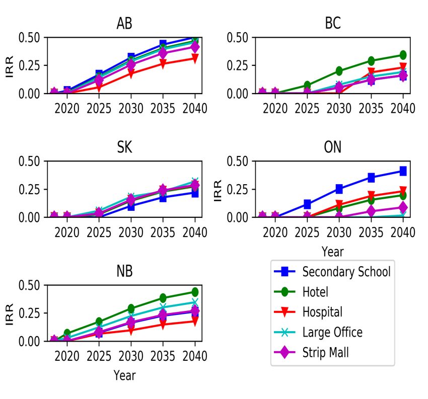
ii                                                                             Canadian Energy Research Institute

Electricity Storage Systems: Applications and Business Cases

Authors:         Ganesh Doluweera
                 Hamid Rahmanifard
                 Mohammad Ahmadi

ISBN 1-927037-65-2

Copyright © Canadian Energy Research Institute, 2019
Sections of this study may be reproduced in magazines and newspapers with acknowledgement to the Canadian
Energy Research Institute

June 2019
Printed in Canada

Front cover photo courtesy of Google images

Acknowledgements:
The authors of this report would like to extend their thanks and sincere gratitude to all CERI staff that provided
insightful comments and essential data inputs required for the completion of this report, as well as those involved
in the production, reviewing and editing of the material, including but not limited to Allan Fogwill and Megan
Murphy.

ABOUT THE CANADIAN ENERGY RESEARCH INSTITUTE
Founded in 1975, the Canadian Energy Research Institute (CERI) is an independent, registered charitable
organization specializing in the analysis of energy economics and related environmental policy issues in the energy
production, transportation and consumption sectors. Our mission is to provide relevant, independent, and objective
economic research of energy and environmental issues to benefit business, government, academia and the public.

For more information about CERI, visit www.ceri.ca

CANADIAN ENERGY RESEARCH INSTITUTE
150, 3512 – 33 Street NW
Calgary, Alberta T2L 2A6
Email: info@ceri.ca
Phone: 403-282-1231

June 2019
Electricity Storage Systems: Applications and Business Cases                                                                                 iii

Table of Contents
LIST OF FIGURES .............................................................................................................                 v
LIST OF TABLES ...............................................................................................................              vii
EXECUTIVE SUMMARY ....................................................................................................                       xi
CHAPTER 1 INTRODUCTION ........................................................................................                              1
    Status of ESS in Canada ......................................................................................................           4
    Scope and Objectives .........................................................................................................           8
CHAPTER 2 REVIEW OF ENERGY STORAGE TECHNOLOGIES .........................................                                                   11
    ESS Technologies Review ...................................................................................................             12
        Compressed Air Energy Storage ..................................................................................                    12
        Pumped Hydro Energy Storage ....................................................................................                    14
        Flywheels......................................................................................................................     14
        Batteries .......................................................................................................................   14
            Electrochemical Batteries ......................................................................................                14
            Flow Batteries ........................................................................................................         16
        Supercapacitors ...........................................................................................................         16
        Hydrogen......................................................................................................................      17
        Thermal Energy Storage ...............................................................................................              17
    Levelized Cost of Storage ...................................................................................................           20
        Future Costs .................................................................................................................      23
CHAPTER 3 ELECTRICITY STORAGE SYSTEMS FOR BEHIND-THE-METER
 APPLICATIONS ..............................................................................................................                27
    Materials and Methods......................................................................................................             28
        Design and Cost Parameters of Lithium-ion Batteries.................................................                                29
        Rate Structures ............................................................................................................        30
    Results and Discussion .......................................................................................................          33
CHAPTER 4 ELECTRICITY STORAGE SYSTEMS FOR BULK ENERGY ARBITRAGE ...............                                                             39
    Materials and Methods......................................................................................................             40
    Results and Discussion .......................................................................................................          43
CHAPTER 5 ELECTRICITY STORAGE SYSTEMS FOR RENEWABLE ENERGY FIRMING ........                                                                 47
    Materials and Methods......................................................................................................             48
        Solar and Wind Resource Data ....................................................................................                   50
        Desired Power Production Profile ...............................................................................                    50
        Generation and Energy Storage Technologies ............................................................                             50
    Results and Discussion .......................................................................................................          52
CHAPTER 6 CONCLUSIONS ..........................................................................................                            57
    Electricity Storage Systems for Behind-the-Meter Applications .......................................                                   58
    Electricity Storage Systems for Bulk Energy Arbitrage ......................................................                            58
    Electricity Storage Systems for Renewable Energy Firming ..............................................                                 59
REFERENCES ...................................................................................................................              61
APPENDIX A LCOS CALCULATION PROCEDURE ..............................................................                                        65
    Peak-Shaving Algorithm .....................................................................................................            69

                                                                                                                                     June 2019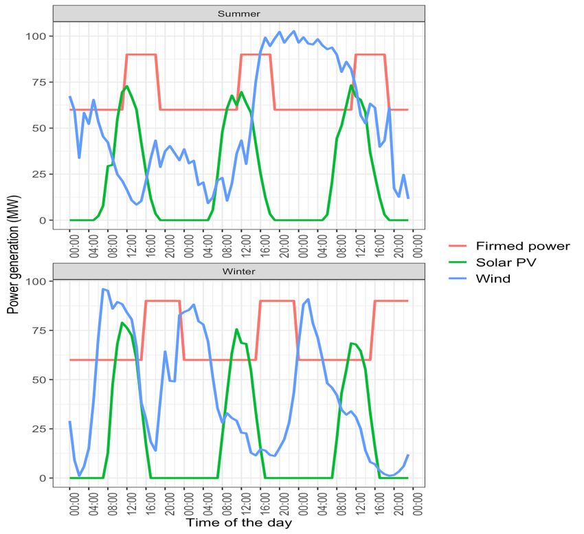
iv          Canadian Energy Research Institute

June 2019
Electricity Storage Systems: Applications and Business Cases v
List of Figures
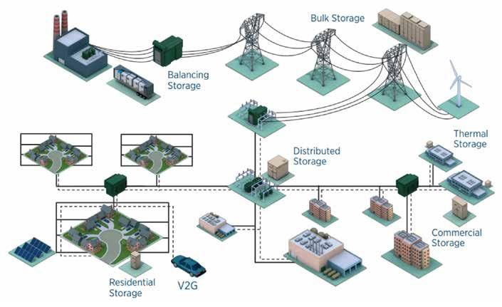
1.1 Locations and Applications of ESS ............................................................................... 1
1.2 ESS Technology Positioning by Technical Attributes and Applications ....................... 3
1.3 Operational ESS Capacity Installed in Canada by Technology ..................................... 8
2.1 Energy Storage Technology Classification ................................................................... 11
2.2 A Typical CAES Plant..................................................................................................... 12
2.3 Hydrostor A-CAES Plant ............................................................................................... 13
2.4 Comparison of Power Density and Energy Density for Selected
Energy Storage Technologies ....................................................................................... 18
2.5 Electrochemical and Thermal Energy Storage Power Capacity by
Technology in Canada .................................................................................................. 20
2.6 LCOS Estimation Flowchart .......................................................................................... 21
2.7 LCOS Variations for Different Technologies and Different Years ................................ 22
2.8 Overnight Cost Variations for Different Technologies and Different Years ................ 23
2.9 Overnight Cost Projections of Different ESS Technologies .......................................... 24
3.1 Behind-the-Meter ESS Applications for Electricity Bill Management.......................... 28
3.2 Analysis Framework for Behind-the-Meter ESS Application Assessment ................... 28
3.3 IRRs of Different Battery Configurations ..................................................................... 34
3.4 IRRs for Five Different Commercial/Institutional Sectors............................................ 35
4.1 An Electricity Storage System in Standalone Arbitrage Mode of Operation ............... 39
4.2 Analysis Framework ..................................................................................................... 39
4.3 Hourly Average Electricity Price Variation, 2015-2018................................................ 42
4.4 IRR Values for CAES, Flow and Li-ion Batteries ............................................................ 45
5.1 Integrated Solar PV, Wind, and ESS Electricity Supply System .................................... 47
5.2 Analysis Framework ..................................................................................................... 49
5.3 Unfirmed and Firmed Electricity Supply Profiles ......................................................... 49
5.4 Distributions of LCOE Values by Province and Investment Year ................................. 52
5.5 Lowest LCOE Reported in Each Province in 2030 and Cost Contribution of the
Main System Components ........................................................................................... 54
5.6 Installed Capacities of System Components ................................................................ 55
5.7 A Sample Storage System Operations Profile Over Two Weeks in Summer in a
Location in Ontario ...................................................................................................... 55
A.1 Schematic Diagram of the Algorithm Used to Calculate PUTh PUTh PUTh PUTh PUTh ..... 72
A.2 The Original and Shaved Load Profiles of a Secondary School in Alberta ................... 74
A.3 Battery Response to Shave the Load Profile of a Secondary School ........................... 75
A.4 IRRs of Different Battery Configurations ..................................................................... 76
June 2019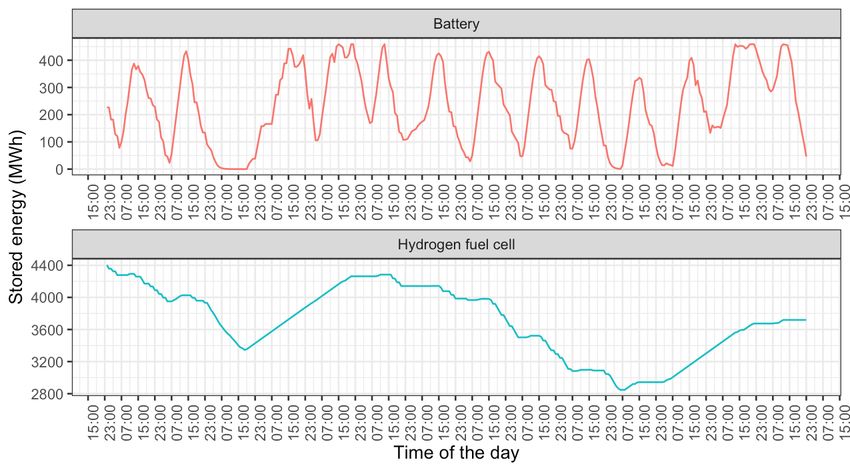
vi          Canadian Energy Research Institute

June 2019

Electricity Storage Systems: Applications and Business Cases                                                                        vii

List of Tables
1.1     Electricity Storage Capacity across Canada .................................................................                 5
2.1     Comparison of Major Energy Storage Technologies by Technical Characteristic .......                                         19
2.2     Relative Capital Costs of ESS Technologies ..................................................................               24
3.1     Design Parameters Used for Lithium-ion Batteries .....................................................                      29
3.2     Projected Costs of Lithium-ion Batteries for 2018-2040 .............................................                        30
3.3     The Utility Rate Structure of Alberta Customers with a Billing Demand of
        150 kW to 5 MW ..........................................................................................................   30
3.4     The Main Components of EPCOR’s Utility Rate Structure for Alberta Commercial/
        Industrial Customers with a Billing Demand of 150 kW to 5 MW ...............................                                31
3.5     The Utility Rate Structure of Large General Service Businesses in British
        Columbia with Annual Electricity Demand of ≥550 MWh ...........................................                             31
3.6     The Utility Rate Structure in Saskatchewan for Commercial Facilities with
        Customer-owned Transformers...................................................................................              32
3.7     The Utility Rate Structure of Class A Customers in Ontario ........................................                         32
3.8     The Utility Rate Structure for Industrial/General Service Customers in
        New Brunswick with Minimum Demand of 750 kW ...................................................                             33
4.1     Descriptive Statistics of Hourly Electricity Prices Observed in Alberta, 2015-2018 ....                                     40
4.2     Storage Technology Specifications ..............................................................................            41
4.3     Charging Time Interval for Each Technology ...............................................................                  42
4.4     IRR Values for CAES, Flow and Li-ion Batteries Based on the Learning Rates for
        2020, 2030 and 2040 ...................................................................................................     44
5.1     Capital and Operating Costs of Generation Technologies Over the Analysis Period ..                                          51
5.2     Capital and Operating Costs of ESS Technologies Over the Analysis Period ...............                                    51
5.3     LCOE of Integrated Solar PV, Wind and Electricity Storage Systems by
        Province and Investment Year .....................................................................................          53

                                                                                                                             June 2019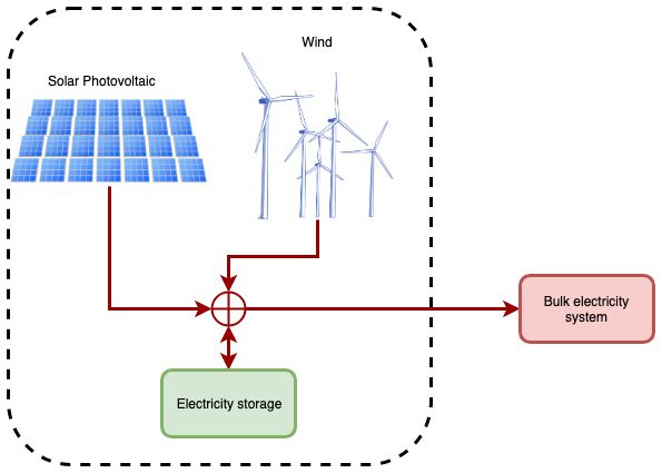
viii        Canadian Energy Research Institute

June 2019
Electricity Storage Systems: Applications and Business Cases                                       ix

Executive Summary
Electricity storage systems (ESS) are gaining the attention of electric utility policy makers and
system operators. Primary factors that have led to this renewed interest include increasing the
share of variable renewable sources in the electricity generation mix, large capital costs of
electricity grid infrastructure required to ensure system reliability, and high costs associated with
managing peak electricity demands. The perceived benefits of ESS have led to new storage
technology developments, demonstration projects, and research projects that quantify the
benefits of ESS systems. This Canadian Energy Research Institute (CERI) study provides an
assessment of three distinct value propositions for following electricity storage applications.

1) Electricity storage systems for behind-the-meter (BTM) applications: We assess the financial
   value of cases where commercial and institutional electricity consumers utilize on-site ESS to
   reduce overall electricity cost. Five types of facilities are assessed.

2) Electricity storage systems for bulk energy arbitrage: We assess the financial value of an
   electricity storage system that operates in energy arbitrage mode where electricity is
   purchased from an energy market in lower price periods and sold back when prices are high.

3) Electricity storage systems for renewable energy firming: We assess the economic cost of
   electricity supplied by a co-located wind, solar photovoltaic (PV), and an electricity storage
   system. An electricity storage system is used to firm up the variable output of wind and solar
   PV to supply dispatchable electricity.

These applications are assessed by considering current and future ESS capital costs. ESS
technologies are currently going through a rapid development and adaptation phase. These
trends could lead to reductions in future capital costs due to technology learning (i.e., the decline
in technology costs due to technology maturity). We conducted a literature review of ESS
technologies to obtain the required data and technology learning rates to estimate the future
ESS capital costs. Lithium-ion (Li-ion) batteries, flow batteries, and hydrogen fuel cells are found
to have the highest future cost reduction potential. All three application assessments are
conducted for three future investment years (2020, 2030 and 2040) to gain insights into the
impacts of changing ESS economics due to technology learning.

Two main energy storage application categories that are excluded in this analysis are ancillary
services and transmission and distribution infrastructure services. Estimation of the value of
energy storage under these application categories requires systems-level detailed modelling
including simulations of generation, transmission, and distribution system operations. Such
analysis is excluded from this analysis but reserved for future work.

Using ESS in commercial and industrial BTM applications has significantly increased over the past
years, primarily because these customers usually pay facility demand charges (sometimes

                                                                                            June 2019
x Canadian Energy Research Institute amounting to 50% of the total utility bill) according to the peak demands recorded during their billing periods. These customers can reduce their demand charges by shifting a fraction of the demand from on-peak to off-peak periods using ESS. The financial value of ESS in BTM applications depends primarily on the load profile of the facility and then on the utility rate structure applicable to that jurisdiction. Noticeable storage cost reductions during the past few years have also promoted this trend and are expected to continue decreasing in most of the ESS technologies. In this study, we employed the peak-shaving technique to reduce the monthly peak demands of commercial and industrial BTM customers to examine how economic it is to use ESS for these applications. Under current rate structures, the utilization of ESS for BTM applications for electricity bill management in the studied provinces (Alberta, Saskatchewan, British Columbia, Ontario, and New Brunswick) starts to be profitable (with an internal rate of return ranging from 7% to 20%) from 2025 onwards. The profitability depends on the amount of peak demand shaving achievable by integrating ESS and the utility rate structure. For a given facility, the shape of the electricity demand profile and the utility rate structure are the primary factors controlling the amount of peak demand reduction achievable by ESS. Generally, the wider the difference between energy and peak demand charges the more profitable the ESS project would be. Also, a flat load profile, with a small window between the minimum and maximum monthly loads, will likely result in a less profitable scenario for the implementation of ESS in BTM applications. In the near term, Li-ion batteries are the most competitive technology option primarily because of their fast response times, widespread commercial availability, and relatively longer life compared to other competing technologies such as the Lead-acid family of batteries. Due to the limitations of the jurisdictional scope and unavailability of future electricity price data at this point, we are unable to make definitive conclusions about the financial value of ESS for bulk energy arbitrage applications. We can, however, point out the following observations that could be considered for future studies to gain more complete insights. Use of ESS for bulk energy arbitrage is found to be not financially attractive under the assumed conditions. The analysis considered three ESS technologies along with their current and future capital costs. The financial value of the electricity arbitrage operation is estimated using electricity prices observed in the Alberta electric energy market over the last four years. None of the conditions we assessed yield favourable financial value for the storage technologies assessed. This is due to two factors. One is the higher capital cost of storage. The other is the lower spread between peak electricity prices and off-peak prices. Standalone bulk energy arbitrage is profitable if the difference between the purchase price and selling price of electricity is sufficient to cover the investment cost and operating expenses. Prices observed in Alberta are not volatile enough to consistently produce wider price spreads to produce favourable conditions for bulk energy arbitrage using ESS. The financial value of ESS in bulk energy arbitrage mode of operation can improve if ESS can tap into multiple revenue streams. These multiple revenue streams could June 2019
Electricity Storage Systems: Applications and Business Cases                                     xi

be revenues earnable through the provision of other power system services such as capacity
services and ancillary services.

Economics of renewable energy firming by ESS was assessed by considering wind and solar
resource availability in 250 locations in 10 Canadian provinces. At each location, we simulate the
operation of a solar photovoltaic (PV), wind, and ESS-based integrated electricity supply system
that has similar availability as a conventional generating unit. A linear optimization model is
developed to determine the optimal system design and to estimate the levelized cost of
electricity (LCOE).

Electricity supplied by the simulated renewable energy system is emissions free and therefore
has the ability to supply zero greenhouse gas (GHG) emissive electricity at a similar level of
reliability as a conventional generating unit. The estimated LCOE values of 250 integrated
electricity supply systems were simulated. Depending on the province, the minimum reported
LCOE is in the range of 16-21 cents/kWh in the investment year 2020, which corresponds to near
term conditions. However, as storage and renewable generation technologies mature, and
capital costs decline due to technology learning, the LCOE declines by about 15-22% by 2030 and
by 22-32% by 2040. The lowest LCOE values are observed in Atlantic Canada, Ontario, and
Manitoba.

In all provinces, the estimated LCOE values are currently higher than conventional generation
technologies such as natural gas combined cycle (NGCC) units. By 2030-2040, variable
renewables and storage combined systems are competitive against other zero GHG emissive
dispatchable technologies such as nuclear power, large hydro, and coal/natural gas-fired units
with carbon capture and storage.

Integrated electricity supply systems, in general, require two types of storage systems to provide
energy arbitrage in two-time scales. Intra-day energy time-shifting can be provided at the lowest
cost by battery systems such as Li-ion and flow batteries. Inter-day and inter-week energy time-
shifting can be economically provided by hydrogen fuel cells. Expected cost declines of hydrogen
fuel cells make them competitive for long-duration storage applications.

Utilities in many jurisdictions – including Canada – have already developed or are currently in the
process of developing grid-scale demonstration projects of co-located ESS and variable
renewable power generating units. As renewables become a larger part of the grid, system
stability considerations may require they include inherent firming and coupling with ESS to
provide a plausible technical solution. Our analysis shows that, regardless of the jurisdiction,
storage systems account for 50% of the cost of electricity supplied by ESS and renewables
combined generation system. Both decline in cost through commercial-scale project
implementation and improvement in storage system efficiency through research and
development.

                                                                                          June 2019
xii Canadian Energy Research Institute June 2019
Electricity Storage Systems: Applications and Business Cases                                     1

Chapter 1: Introduction
Electricity storage systems (ESS) are gaining the attention of electric utility policy makers and
system operators. Primary factors that have led to this renewed interest include increasing share
of variable renewable sources in the electricity generation mix, large capital costs of electricity
grid infrastructure required to ensure system reliability, decreasing storage costs, and high costs
associated with managing peak electricity demands. Furthermore, ESS is considered as
facilitating technologies of smart electric grids that have the inherent capability to respond to
dynamic changes in electricity demand, supply, and various exogenous factors that impact
electric power systems.

The perceived benefits of ESS have led to new storage technology developments, demonstration
projects, and research projects that quantify the benefits of ESS. The past five years saw rapid
growth in the global adaptation of ESS. Global installed capacity of ESS has grown by 8 times,
from 400 MW/year in 2014 to 3,100 MW in 2018. According to a forecast by Bloomberg New
Energy Finance, the global energy storage market will grow to a cumulative installed capacity of
2,857 GWh by 2040. According to the same forecast, the rapid growth in the ESS market will
attract US$620 billion in investments over the next 22 years.

                             Figure 1.1: Locations and Applications of ESS

                                                                                          June 2019
2 Canadian Energy Research Institute In general, a storage system can absorb energy, and store it for a period of time before releasing it to the electricity system. Through this process, ESS can temporally decouple electricity supply and demand. As shown in Figure 1.1, ESS systems have multiple applications in electricity systems ranging from the utility-scale electricity grid to behind-the-meter applications. Current ESS applications can be broadly categorized into application types as follows (Schmidt et al. 2019; Akhil et al. 2016a). Bulk energy services ESS systems can provide utility-scale energy and capacity services. The most understood and primary ESS application in this category is energy arbitrage. This involves time-shifting of energy where an ESS system is charged at one point in time and then discharged at a later time. Time shifting of energy on the bulk energy system can potentially make economic sense under two situations. One situation is charging ESS when inexpensive electricity is available – for example, in the case of low demand periods – and then discharged and sold back to the grid when electricity prices (or costs) are high. Another situation is time-shifting of excess electricity production, which would otherwise be curtailed. This applies primarily for variable renewable electricity generation sources such as wind and solar photovoltaic where generation cannot be controlled. One main driver for the current interest in ESS is renewable energy arbitrage (IRENA 2017; Akhil et al. 2016a; John 2017). Another bulk energy service that can be satisfied by ESS is to defer or reduce the need to buy new generation capacity. By flattening load and generation curves, energy storage can service peak demand without building new generation assets. ESS can act as an electricity supply capacity resource and be available to be called upon to satisfy the demand in peak demand periods. Ancillary services Ancillary services are grid support services that are required to operate the bulk electricity system reliably. All electricity systems require an array of ancillary services such as frequency regulation, spinning and non-spinning reserves, regulation reserves, voltage support, black start, and load following/ramping reserves. Currently, these services are primarily sources from traditional generation and transmissions assets. Different ESS technologies can provide all of these ancillary services. Some of these ancillary services are primarily used to match the time-varying electricity supply and demand. Integration of variable renewables will increase the need for ancillary services such as load following/ramping reserves. Use of ESS to reduce the overall cost of those ancillary services is considered as an enabling factor for large scale renewable energy integration (Akhil et al. 2016a; IRENA 2017). June 2019
Electricity Storage Systems: Applications and Business Cases 3
Transmission and distribution infrastructure services
The main application in this category is deferral and, in some situations, completely avoiding
requirements to upgrade transmission and distribution system assets (includes wires,
transformers, and substations) by using relatively smaller amounts of ESS. Transmission and
distribution system costs require significant capital investments and therefore any technical
option to reduce the needs for upgrades can lower the overall electricity cost.
For example, in Alberta, the transmission facility operator – Altalink – is currently developing an
ESS project to defer transmission system expansion. The “Whitecourt Transmission Deferral
Battery Project” involves installing a 20 MW/20 MWh Battery Energy Storage System (BESS) at
the existing Whitecourt substation, minimizing or eliminating the need to build a new
transmission line in the area (Emissions Reductions Alberta 2019).
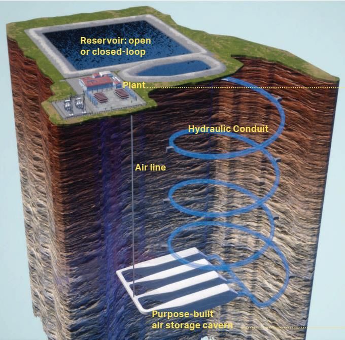
Figure 1.2: ESS Technology Positioning by Technical Attributes and Applications
The different applications described above have varying levels of ESS capacity and storage
duration requirements. Applications such as energy arbitrage require relatively larger electricity
discharge power ratings with several hours of storage time. On the other hand, ancillary services
may only require a few minutes to an hour of storage duration. Different ESS have different
capacity and storage duration ratings. Figure 1.2 shows the typical ratings of different storage
technologies and their suitability for various electricity applications. For instance, pumped hydro
storage (PHS) and compressed air energy storage (CAES) technologies are suitable for bulk power
June 20194 Canadian Energy Research Institute management due to their discharge duration (multiple hours), while flywheel and supercapacitor technologies have shorter discharge duration, which makes them appropriate for improving the power quality. Customer side energy management services Siting ESS on the customer side (also known as behind-the-meter applications) can reduce the overall cost for electricity consumers in several ways. This can be done by increasing the power quality, increasing reliability, reducing the overall electricity bill by reducing or avoiding demand charges, managing electricity consumption under time of use electricity pricing schemes, and by facilitating self-generation of electricity. According to Bloomberg NEF, by 2040, the global ESS market will be dominated by behind-the-meter applications. One main advantage of ESS for behind-the-meter applications is their scalability, where an ESS system can be optimized in terms of size and technical features to match specific customer needs. Status of ESS in Canada The total installed capacity of all types of energy storage in the world is about 176 GW, with three countries – China (32.1 GW), Japan (28.5 GW), and the US (24.2 GW) – accounting for half of the global energy storage capacity. PHS technology represents the largest power source of 169 GW (around 96%) followed by thermal storage (3.3 GW), electrochemical batteries (1.9 GW) and electro-mechanical storage (1.6 GW). In Canada, the operational ESS capacity is about 202 MW. As shown in Figure 1.3, of all the operational ESS projects in Canada, PHS technology represents the largest share at 174 MW of power (86%) followed by electrochemical batteries with 26.4 MW (13%) and thermal storage with 1.5 MW (0.8%). Table 1.1 lists the operational and proposed ESS projects in Canada. As evident from the current operational projects and the proposed ESS projects, there is approximately 4,500 MW of ESS capacity being projected across the country. June 2019
Electricity Storage Systems: Applications and Business Cases                                          5

                        Table 1.1: Electricity Storage Capacity across Canada

 Project                           Location                    Technology     Power
                                                                              (kW)    Status
 RES Amphora                       Strathroy, Ontario,         Lithium Iron   4000    Operational
                                                               Phosphate
                                                               Battery
 Vancouver                         Vancouver, British          Lithium        1000    Operational
 Electrochemical Energy            Columbia                    Nickel
 Storage Project –                                             Manganese
 University of British                                         Cobalt
 Columbia                                                      Battery
 PowerStream                       Penetanguishene,            Lithium        750     Operational
 Penetanguishene                   Ontario                     Polymer
 Microgrid                                                     Battery
 Toronto Hydro CES Project         Toronto, Ontario            Lithium        500     Operational
 – eCAMION                                                     Polymer
                                                               Battery
 14.8 MW / 58.8 MWh                Toronto, Ontario            Lithium-ion    14800   Operational
 IESO Energy Storage                                           Battery
 Procurement Phase 1 –
 Hecate Energy (Toronto
 Installation)
 Esstalion Technologies            Varennes, Quebec            Lithium-ion    1200    Operational
 Varennes Energy Storage                                       Battery
 System
 Saft 232 kWh BESS Arctic          Colville Lake,              Lithium-ion    1100    Operational
 Circle                            Northwest                   Battery
                                   Territories
 500 kW – Microgrid                Oshawa, Ontario             Lithium-ion    500     Operational
 Research and Innovation                                       Battery
 Park at University of
 Ontario Institute of
 Technology (UOIT)
 Regina High Wind and              Regina,                     Lithium-ion    400     Operational
 Storage Project –                 Saskatchewan                Battery
 Cowessess First Nation
 Oshawa Power / Tabuchi            Oshawa, Ontario             Lithium-ion    150     Operational
 Electric – 30 Home Solar-                                     Battery
 Plus-Storage Pilot – 5 kW /
 10 kWh per home
 Panasonic Eco Solutions           Vaughan, Ontario            Lithium-ion    2       Operational
 Canada- Vaughan                                               Battery

                                                                                               June 2019
6 Canadian Energy Research Institute
Sir Adam Beck Niagara-on-the- Open-loop 174000 Operational
Hydroelectric Generating Lake, Ontario Pumped
Station Hydro
Storage
Toronto Zoo – Ice Energy Toronto, Ontario Ice Thermal 15 Operational
Storage
Wind Energy Institute of North Cape, Prince Sodium- 1000 Operational
Canada Wind R&D Park Edward Island nickel-
and Storage System for chloride
Innovation in Grid Battery
Integration
BC Hydro Field Battery Field, British Sodium- 1000 Operational
Energy Storage Columbia sulphur
Battery
Minto Flywheel Facility Minto, Ontario Flywheel 2000 Operational
Goderich CAES Goderich, Ontario Advance 1750 Construction
Demonstration Project CAES completed;
Currently being
commissioned
Hydrogenics Power-to-Gas Greater Toronto Hydrogen 2000 Contracted
Area, Ontario Storage
Sault Ste. Marie Energy Sault Ste. Marie, Lithium-ion 7000 Contracted
Storage – Convergent + Ontario Battery
GE / IESO
Canadian Solar Solutions Ontario, Ontario Lithium-ion 4000 Contracted
for IESO Battery
5 MW / 20 MWh – TBD, Ontario Vanadium 5000 Contracted
Ontario IESO – SunEdison Redox Flow
/ Imergy Flow Battery Battery
Milton-IESO Milton, Ontario Vanadium 2000 Contracted
Redox Flow
Battery
2 MW / 6 MWh ViZn IESO (TBD), Zinc Iron 2000 Contracted
Energy – Ontario IESO Ontario Flow Battery
Project – Hecate Energy
Marmora Pumped Storage Marmora, Ontario Closed-loop 400000 Announced
Pumped
Hydro
Storage
SunEdison Canada Ontario, Ontario Electro- 5000 Announced
Origination LP-IESO chemical
Ameresco Canada Inc- Ontario, Ontario Lithium-ion 4000 Announced
IESO Battery
June 2019Electricity Storage Systems: Applications and Business Cases 7
NextEra Canada Ontario, Ontario Lithium-ion 2000 Announced
Development & Battery
Acquisitions, Inc.- Parry
NextEra Canada Ontario, Ontario Lithium-ion 2000 Announced
Development & Battery
Acquisitions, Inc.-Elmira
Veridian-Ontario- Sault Ste. Marie, Lithium-ion 10 Announced
Microgrid Ontario Battery
Revelstoke Hydro Battery Revelstoke, British Pumped 4000000 Announced
Columbia Hydro
Storage
Canyon Creek Pumped Hinton, Alberta Pumped 75000 Regulatory
Hydro Energy Storage Hydro approval
Project Storage received.
Whitecourt Transmission Whitecourt, Battery 20000 Proposed.
Deferral Battery Alberta Partial Funding
Received from
Emissions
Reduction
Alberta (ERA)
ENMAX Midstream Rimbey, Alberta Lithium-ion Proposed.
Industrial Solar and Partial Funding
Storage Project Received from
ERA
Saddlebrook Solar and Aldersyde, Alberta Lithium-ion Proposed.
Storage Partial Funding
Received from
ERA
FortisAlberta Waterton Waterton, Alberta Proposed.
Energy Storage Project Partial Funding
Received from
ERA
Drumheller Solar and Drumheller, Lithium-ion 8000 Proposed.
Battery Storage Project Alberta Partial Funding
Received from
ERA
Source: (DOE 2019b; Emissions Reductions Alberta 2019; NRStor 2019)
Figure 1.3: Operational ESS Capacity Installed in Canada by Technology
June 20198 Canadian Energy Research Institute
Data source: DOE 2019
Scope and Objectives
Currently, there is high interest in ESS globally as well as in Canada. Energy storage can be used
to mitigate the challenges faced by Canadian power systems and electricity consumers. This CERI
study provides an assessment of three distinct value propositions for electricity storage
applications.
The three application are as follows:
1) Electricity storage systems for behind-the-meter applications: We assess the financial
value of cases where commercial and instructional electricity consumers utilizing on-site
electricity storage systems to reduce overall electricity cost. Five types of commercial and
institutional electricity consumers are assessed.
2) Electricity storage systems for bulk energy arbitrage: We assess the financial value of an
electricity storage system that operates in energy arbitrage mode where electricity is
purchased from an energy market in lower price periods and sold back when prices are
high.
3) Electricity storage systems for renewable energy firming: We assess the economic cost of
electricity supplied by a co-located wind, solar photovoltaic (PV), and an electricity
storage system. An electricity storage system is used to firm up the variable output of
wind and solar PV to supply dispatchable electricity. This assessment covers all 10
Canadian provinces and we estimated the cost of developing a dispatchable renewable
electricity supply system in approximately 250 locations.
We primarily use two metrics for the assessment, namely, internal rate of return (IRR) and
levelized cost of electricity (LCOE). The first two application cases take the perspective of a private
investor whose objective is to reduce the cost of business operations (case 1) or make revenue
out of electricity trading. IRR is an appropriate metric to inform such investment decision making.
June 2019Electricity Storage Systems: Applications and Business Cases 9
The renewable energy firming application under case 3, takes the electricity generator investors’
perspective.
In most jurisdictions, electric utilities are regulated entities who set rates under the principle of
cost of service. In such cases, LCOE is the more appropriate metric. Two exceptions are the
electricity systems of Ontario and Alberta where electricity systems are de-regulated, and
electricity generation is a competitive business. In those cases, too, LCOE serves as a useful metric
to compare competing generation options as well as to screen cost of business under different
market and regulatory conditions.
Two main energy storage application categories that are excluded in this analysis are ancillary
services and transmission and distribution infrastructure services. Estimation of the value of
energy storage under these application categories requires systems-level detailed modelling
including simulations of generation, transmission, and distribution system operations. Such
analysis is excluded from this analysis but reserved for future work.
The remainder of this report is organized as follows: Chapter 2 provides a brief review of storage
technologies, the global and Canadian status of energy storage systems, and a review of the
current and future cost of storage. Chapters 3, 4, and 5 present the methodology and results of
the three value propositions assessed. Chapter 6 concludes.
June 201910 Canadian Energy Research Institute June 2019
Electricity Storage Systems: Applications and Business Cases                                   11

Chapter 2: Review of Energy Storage
Technologies
A survey of literature on ESS technologies that we conducted provided information about a large
set of ESS technologies with different technical attributes (capacity ratings, storage duration,
efficiency, etc.) and varying levels of technical maturity.

In this study, for further analysis, we only consider PHS, CAES, batteries (sodium, lead-acid, Li-
ion, flow, zinc), flywheel, hydrogen (fuel cell), and thermal storage technologies. These
technologies are selected by considering their technical maturity and suitability for applications
with higher importance for Canadian electricity systems. These ESS technologies can be
categorized by the underlying storage mechanism as depicted in Figure 2.1. The next section
presents a brief description of those select ESS technologies.

                           Figure 2.1: Energy Storage Technology Classification

Source : (WES 2016; Argyrou et al. 2018).

                                                                                         June 2019
12 Canadian Energy Research Institute
ESS Technologies Review
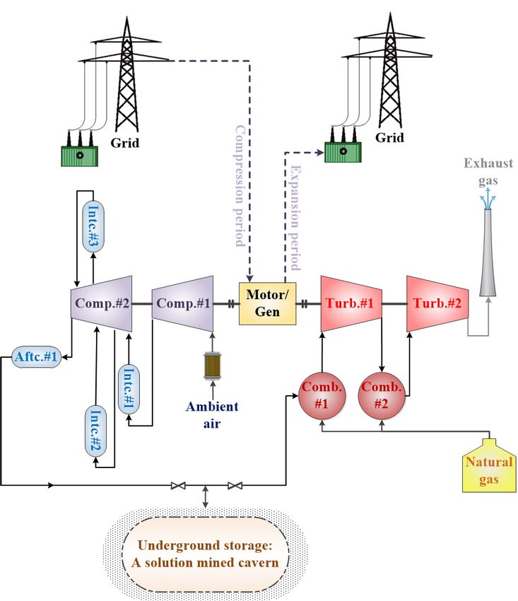
Compressed Air Energy Storage (CAES)
In CAES, air is compressed during the off-peak time, the high-pressure air is injected into the
geological structures (e.g., mines, aquifers, salt caverns, depleted hydrocarbon reservoirs) or
aboveground pressure vessels. The air is then released to drive the turbine for electricity
generation when the electricity is needed (Figure 2.2). The total nominal capacity of CAES is 440
MW globally (Kapila 2018). There are two types of CAES including conventional compressed air
energy storage (C-CAES) and adiabatic compressed air energy storage (A-CAES).
In C-CAES, the heat from the compression stage is released into the atmosphere, while during
the expansion stage, to prevent low temperatures in the turbine, the air is preheated using the
natural gas (Figure 2.2). CAES power plants in Huntorf, Germany and Alabama, US with installed
capacity of 290 MW and 110 MW, respectively, are two examples of commercialized C-CAES ,
whereas two other CAES plants in Apex Bethel Energy Center, Texas and Larne, Northern Ireland
are in the development phase (Apex 2019; ENTSOE 2019; Mannan et al. 2014).
Figure 2.2: A Typical CAES Plant
June 2019Electricity Storage Systems: Applications and Business Cases 13
In A-CAES, the heat generated in the compression stage is captured using a thermal energy
storage system, which is then used to preheat the air before going through the expander (Kapila
2018). This type of technology does not use any natural gas which makes it a zero-emission
technology. A commercial A-CAES technology proposed by Hydrostor (Hydrostor 2018) consists
of three main components including the plant (compressors, turbines, and heat exchangers), a
closed-loop water reservoir for maintaining hydrostatic pressure, and the subsurface
infrastructure (decline portal, decline, air accumulators, and thermal store). In this technology,
heated compressed air is produced using the off-peak grid electricity or surplus electricity from
renewable sources. The generated heat from the compression is then extracted from the air and
stored in thermal energy storage (TES) for later use. Thereafter, the compressed air is stored in
the underground air accumulators where it is hydrostatically compensated displacing water into
the closed-loop water reservoir. During the discharge cycle, the hydrostatic pressure forces the
compressed air to flow to the surface and through the TES for preheating and running the
expander for electricity generation (Figure 2.3).
Figure 2.3: Hydrostor A-CAES Plant
(Hydrostor 2018)
June 201914 Canadian Energy Research Institute A technical demonstration A-CAES was been built by Hydrostor in 2015 in Toronto Island, Ontario. NRStor Inc. is developing an A-CAES commercial demonstration project in Goderich, Ontario. The project is contracted by the IESO and is currently in the commissioning phase. Other A-CAES projects currently in operation include Angas A-CAES Project by Hydrostor in Strathalbyn, Australia and the ADELE A-CAES plant (Hydrostor 2018; Mannan et al. 2014; RWE Power 2010). Pumped Hydro Energy Storage (PHS) PHS has been the most common way of storing energy over the past century. The principle operation of PHS is pumping the water from a lower level reservoir and storing it in a higher basin reservoir during the off-peak time and flowing the water in the reverse direction through turbines when electricity is needed. There are more than 300 PHS plants with a total nominal capacity of 169 GW globally, among which the one in Virginia, US is the largest plant with a capacity of 3 GW for the 10-hour duration. In Alberta, a pump hydro storage project is currently in the development stage. This project will expand and retrofit the existing Brazeau Hydro electricity generation system to a 600-900 MW PHS facility (Thompson 2017). Flywheels Flywheels are suitable for operations that require high power within a short time period. They store the kinetic energy of a spinning mass (rotor) and perform as a motor during charging and a generator while discharging. There are two types of flywheels: low speed (< 6,000 rpm) and high speed (< 60,000 rpm) (WES 2016; Argyrou, Christodoulides, and Kalogirou 2018a). Batteries In recent years, batteries have become one of the most popular storage technologies, especially for small applications such as automotive and cellphones. Among different battery technologies, electrochemical batteries such as lithium-ion (Li-ion) and lead-acid are currently the leading technologies in service, while other types of technologies such as flow batteries are in the development phase. A large number of battery electricity storage projects are currently in development in Canada and around the world (DOE 2019b; Emissions Reductions Alberta 2019). The operation principle of electrochemical and flow batteries is to convert the electricity to chemical energy and then convert back to electricity during charging and discharging periods. Note that the chemical energy for electrochemical batteries is in the form of charged ions, while it is two charged liquid electrolyte solutions for flow batteries. Electrochemical Batteries Lead-acid Lead-acid is the most mature and widely used battery technology suitable for power quality and spinning reserve applications (Akhil et al. 2016b; Argyrou, Christodoulides, and Kalogirou 2018b). Lead-acid batteries are used in vehicles and various stationary applications. They consist of lead- dioxide (PbO2) as the positive electrode, metallic lead (Pb) as the negative electrode, and a sulfuric acid solution (usually around 37% by weight) as the electrolyte. During discharge, H+ ion June 2019
Electricity Storage Systems: Applications and Business Cases                                     15

formed at the negative electrode goes into the electrolyte and is then consumed by the positive
electrodes. The reverse reaction occurs during the charge cycle.

Lead-acid batteries are divided into two technologies: lead-acid carbon and advanced lead-acid.
In lead-acid carbon technologies, to mitigate the effects of partial states of charge and improve
the power characteristics of the battery, the negative electrode is replaced with the carbon
electrode. Advanced lead-acid technology is a combination of classic lead-acid cell and lead-acid
carbon battery, which means that in these batteries, the negative electrode includes metallic
lead (Pb) and carbon electrode (WES 2016).

Lithium-ion family (Li-ion)

Li-ion batteries are another commercial and mature technology mainly used in electric vehicles
and cellphones. Similarly, these batteries consist of the anode (graphite), the cathode (e.g.,
lithium cobalt oxide, lithium iron phosphate, lithium manganese oxide), and an electrolyte
(lithium salt). In these batteries, during the discharge cycle, Li+ ions are produced from the
negative electrode (anode) and move to the cathode (positive electrode). The reaction is in the
reverse direction during charging time (WES 2016).

Sodium-sulfur (NaS)

NaS batteries are constructed in a tubular design where the anode and the cathode are sodium
(Na) and sulphur (S) with a solid electrolyte of beta alumina. During discharge, sodium is oxidized
at the interface of the anode and the electrolyte forming Na+ ions, which migrate through the
solid electrolyte and then release electrons around the cathode. The operational temperature
range and cycle life of these batteries are 300°C to 350°C and 2,500-4,500 cycles (WES 2016;
IRENA 2017).

Sodium-nickel-chloride (NaNiCl)

These batteries consist of nickel chloride (NiCl2) as the cathode, liquid sodium as the anode, and
ceramic electrolyte to separate the electrodes, which isolates the electrons but is conductive for
sodium ions. During charging and discharging, salt and nickel are reversibly converted into
molten sodium and nickel chloride, which absorbs or releases electrons. The operational
temperature range varies between 270°C to 350°C (Argyrou et al., 2018).

Zinc-air

These batteries are a metal-air electrochemical cell technology, which consist of the anode made
of metal (e.g., zinc, aluminum, magnesium, or lithium), the cathode from a porous carbon
structure connected to an air supply, and the electrolyte, which is a liquid form or a solid polymer
membrane and is conductive to OH-ion (metal-ion) (Argyrou et al., 2018).

                                                                                           June 2019
16 Canadian Energy Research Institute Flow Batteries Vanadium Redox (VR) The operation principle of VR batteries is based on the reduction and oxidation (redox) reactions, which transfer electrons between vanadium ions in different oxidation stages. In the negative electrolyte, during the charging period, V3+ ions are reduced to V2+ ions, whereas they are converted back (V2+ to V3+) during the discharge cycle. Similarly, in the positive electrolyte, V4+ ions are reversibly oxidized to V5+ ions through the release of electrons. Note that the two electrolytes are separated from each other by a hydrogen ion conductive membrane for maintaining charge neutrality (WES 2016; Argyrou, Christodoulides, and Kalogirou 2018a). Iron-chromium (Fe-Cr) These batteries store energy by using iron (Fe2+ and Fe3+) and chromium (Cr2+ and Cr3+) ions as the redox couples. During the discharge period, Cr2+ is converted to Cr3+ in the negative electrolyte, while Fe2+ is reduced to Fe3+ in the positive side of the cell (these reactions are reversed for charging cycle). Like VR batteries, the two electrolytes are separated from each other by a hydrogen ion conductive membrane for maintaining charge neutrality (ESA 2019a). Zinc-bromine (Zn-Br) Zn-Br batteries are hybrid redox flow batteries, which consist of two carbon-plastic composite electrodes, two different electrolytes (a purely water-based electrolyte on the negative side and an electrolyte with an organic amine compound on the positive side) and a microporous polyolefin membrane. During the charging cycle, zinc metal is reduced as a solid and forms a thick film onto the anode side of the electrode, while bromide ions are converted to bromine, which reacts with the organic amine and forms a bromine-adduct oil. During discharge time, the reaction reverses (ESA 2019b). Supercapacitors These technologies consist of two electrodes made of high surface area materials such as porous carbon where the energy storage is not achieved through a chemical reaction. The electrolyte is organic or aqueous. During charging and discharging cycles, electrically charged ions in the electrolyte are moved towards the electrodes of opposite charge (Argyrou, Christodoulides, and Kalogirou 2018a). In these technologies, the higher surface area leads to better electrostatic charge storage. Therefore, the replacement of graphene for activated porous carbon is often recommended in supercapacitors. This makes the graphene-based supercapacitors store almost the same energy as lithium-ion batteries, charge and discharge in seconds, and maintain all this over the charging cycles (Graphene-info 2019). June 2019
Electricity Storage Systems: Applications and Business Cases                                      17

Hydrogen
When the electricity price is low (off-peak periods), electrolysis could be utilized for hydrogen
production. The hydrogen is then stored in storage tanks, which could be categorized into four
groups according to deployed technologies (Argyrou et al., 2018):

    •   pressurized hydrogen methods using high permeable materials to hydrogen,
    •   metal hydrides storage media,
    •   liquid hydrogen storage,
    •   and carbon nanofibers media.

During the on-peak periods, the stored hydrogen is converted to electricity using fuel cells to
generate electricity. Like batteries, fuel cells consist of an electrolyte (a hydrogen ion conductive
membrane) and two electrodes, anode, and cathode, which are fed by hydrogen and an oxidant
(oxygen or air), respectively. The electricity is generated based on the potential difference
between the two electrodes (Argyrou et al., 2018). The most common types of fuel cells in ESS
applications are polymer electrolyte membrane and alkaline fuel cells (NREL 2018).

Thermal Energy Storage (TES)
TES is the temporary storage of thermal energy, which can be divided into two types of
technologies:

    •   Low-temperature TES: These technologies are used for cooling and heating of industrial
        and commercial buildings (e.g., aquiferous low-temperature TES and cryogenic energy
        storage (CES))
    •   High-temperature TES: These technologies are under development and used in heat
        recovery and renewable energy technologies (e.g., Concrete storage plants (CSP) and
        Phase Change Materials (PCM))

Figure 2.4 shows power density versus energy density for each storage technology according to
the size of storage devices. At a given energy amount, high power densities and energy densities
demonstrate the feasibility of smaller ESS, while lower power or energy densities may mean that
larger volumes are required.

                                                                                           June 2019
18 Canadian Energy Research Institute
Figure 2.4: Comparison of Power Density and Energy Density for
Selected Energy Storage Technologies
Source: (IRENA 2017)
In addition, the comparison among the major energy storage technologies in terms of their
technical characteristics and their energy performances are provided in Table 2.1.
June 2019Electricity Storage Systems: Applications and Business Cases 19
Table 2.1: Comparison of Major Energy Storage Technologies by Technical Characteristic
Power Discharge Response
Cycles, or Self-
Technology Rating Time Efficiency Time
Lifetime Discharge
(MW) (hrs) (sec)
20,000 – 70% –
Pumped Hydro 10 - 5000 1 – 24+ ~0 > 10
50,000 85%
Compressed 40% –
5 - 1000 1 – 24+ > 13,000 ~0 > 10
Air 70%
25% –
Hydrogen 0.01 - 500 0.02-24 < 20,000 < 4% < 10
45%
Lead- 0.1% - 80% –
0.001-100 0.02 – 10 < 5,500 < 10
acid 0.3% 90%
1,000 – 0.1% - 85% –
Batteries
Li-ion 0.001 - 100 0.02 – 8 < 10
10,000 0.3% 95%
Sodium 2,500 – 0.05% - 70% –
0.05 - 100 0.02 – 8 < 10
Sulphur 4,500 20% 90%
5,000 – 60% –
Flow 0.02 - 100 0.02-10 0.2% < 10
14,000 85%
Molten Salt
80% –
(latent 1 - 150 hours 30 years - > 10
90%
thermal)
Supercapacitor20 Canadian Energy Research Institute
Figure 2.5: Electrochemical and Thermal Energy Storage Power Capacity by
Technology in Canada
Source: (DOE 2019a)
Levelized Cost of Storage (LCOS)
As part of the review and data collection for this study, we examined the cost estimates of
different ESS technologies published by different companies and institutes. The objective was to
gain insights into the evolution of ESS technologies and also to compare different technologies.
The collected data is utilized to estimate a metric called levelized cost of storage (LCOS) (Schmidt
et al. 2019). LCOS is the average cost of cycling electricity through an ESS device to deliver a unit
of electricity (i.e., a 1 kWh/1 MWh of electricity). LCOS considers the investment and operating
costs of an ESS and an expected rate of return. The LCOS in this study is calculated according to
the flowchart depicted in Figure 2.6. Further details about our procedure and the model are
provided in Appendix A.
June 2019Electricity Storage Systems: Applications and Business Cases 21
Figure 2.6: LCOS Estimation Flowchart
Based on the above flowchart, the procedure explained in Appendix A, and the literature data
(Lazard 2015, 2016, 2017, 2018; Black & Veatch 2012; Sandia 2015; Energy and Environmental
Economics 2017), we estimate the LCOS of different ESS technologies. Figure 2.7 depicts the
estimated LCOS values by technology against the year in which the estimate was published.
June 2019You can also read