EVOS FL Auto EVOS Onstage Incubator - imaging system for Fluorescence and Transmitted Light Applications
←
→
Page content transcription
If your browser does not render page correctly, please read the page content below
user guide

EVOS® FL Auto
EVOS® Onstage Incubator
Imaging System for Fluorescence
and Transmitted Light Applications

Catalog Numbers AMAFD1000, AMC1000

Publication Number MAN0007986
Revision C.0

For Research Use Only. Not for use in diagnostic procedures.
Information in this document is subject to change without notice.

DISCLAIMER
LIFE TECHNOLOGIES CORPORATION AND/OR ITS AFFILIATE(S) DISCLAIM ALL WARRANTIES WITH
RESPECT TO THIS DOCUMENT, EXPRESSED OR IMPLIED, INCLUDING BUT NOT LIMITED TO THOSE OF
MERCHANTABILITY, FITNESS FOR A PARTICULAR PURPOSE, OR NON-INFRINGEMENT. TO THE EXTENT
ALLOWED BY LAW, IN NO EVENT SHALL LIFE TECHNOLOGIES AND/OR ITS AFFILIATE(S) BE LIABLE,
WHETHER IN CONTRACT, TORT, WARRANTY, OR UNDER ANY STATUTE OR ON ANY OTHER BASIS FOR
SPECIAL, INCIDENTAL, INDIRECT, PUNITIVE, MULTIPLE OR CONSEQUENTIAL DAMAGES IN CONNECTION
WITH OR ARISING FROM THIS DOCUMENT, INCLUDING BUT NOT LIMITED TO THE USE THEREOF.

Important Licensing Information
These products may be covered by one or more Limited Use Label Licenses. By use of these products, you
accept the terms and conditions of all applicable Limited Use Label Licenses.

TRADEMARKS
All trademarks are the property of Thermo Fisher Scientific and its subsidiaries unless otherwise specified.
Cy is a registered trademark of GE Healthcare UK Limited.
DRAQ5 is a registered trademark of Biostatus Limited.
Windows is a registered trademark of Microsoft Corporation.
Kimwipes is a registered trademark of Kimberly-Clark Corporation.
Hoechst is a registered trademark of Hoechst GmbH.
Swagelok is a registered trademark of Swagelok Company.

© 2014 Thermo Fisher Scientific Inc. All rights reserved.
Contents

  About This Guide ..................................................................................................................... 3
  1. Installation ........................................................................................................................ 4
       Standard Items Included ................................................................................................................................ 4
       Operating Environment.................................................................................................................................. 4
       Set Up ................................................................................................................................................................ 5
  2. Basic Operation ................................................................................................................. 7
       Image Capture ................................................................................................................................................. 7
       Save ................................................................................................................................................................. 10
  3. Edit and Analyze Images ..................................................................................................11
       Overlay ........................................................................................................................................................... 11
       Measure .......................................................................................................................................................... 12
       Count ............................................................................................................................................................... 14
       Auto Count ..................................................................................................................................................... 16
       Image Review................................................................................................................................................. 18
  4. Advanced Operations .......................................................................................................19
       Image Settings ................................................................................................................................................ 19
       Scan.................................................................................................................................................................. 22
       Time Lapse ..................................................................................................................................................... 28
       Movies ............................................................................................................................................................. 33
  5. System .............................................................................................................................40
       Basic Tab ......................................................................................................................................................... 40
       Network tab ................................................................................................................................................... 42
       Service Tab ..................................................................................................................................................... 43
  6. Care and Maintenance......................................................................................................44
       General Care................................................................................................................................................... 44
       Objective Lens Care....................................................................................................................................... 44
       Stage Care ....................................................................................................................................................... 45
       Sterilization Procedures ................................................................................................................................ 45
       Software Updates .......................................................................................................................................... 46
       Calibrate Objectives ...................................................................................................................................... 47
       Calibrate Vessel Alignment.......................................................................................................................... 50
       Change the EVOS® LED Light Cube ........................................................................................................... 51
       Change the Objectives .................................................................................................................................. 52
       Install the Shipping Restraint ...................................................................................................................... 53

                                                                                                                                                                              1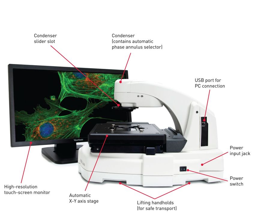
7. Troubleshooting ...............................................................................................................54
         Image Quality Issues ..................................................................................................................................... 54
         Software Interface Issues .............................................................................................................................. 55
         Mechanical Issues .......................................................................................................................................... 55
    Appendix A: Description of EVOS® FL Auto Imaging System...................................................56
         Technical Specifications ................................................................................................................................ 56
         Instrument Exterior Components ............................................................................................................... 58
         Operation Principles and Technical Overview ......................................................................................... 59
    Appendix B: EVOS® Onstage Incubator ...................................................................................60
         Technical Specifications ................................................................................................................................ 61
         EVOS® Onstage Incubator Exterior Components ..................................................................................... 62
         EVOS® Onstage Incubator Control Unit Instrument Panel ..................................................................... 62
         EVOS® Onstage Incubator Stagetop Environmental Chamber ............................................................... 63
         Installing the EVOS® Onstage Incubator .................................................................................................... 64
         Using the EVOS® Onstage Incubator .......................................................................................................... 69
         General Care of the EVOS® Onstage Incubator ......................................................................................... 71
         Sterilization Procedures ................................................................................................................................ 71
    Appendix C: Safety .................................................................................................................72
         Safety Conventions Used in this Document .............................................................................................. 72
         Symbols on Instruments ............................................................................................................................... 73
         Safety Labels on Instruments ....................................................................................................................... 75
         General Instrument Safety ........................................................................................................................... 76
         Safety Requirements for EVOS® Onstage Incubator ................................................................................. 77
         Chemical Safety ............................................................................................................................................. 78
         Chemical Waste Safety ................................................................................................................................. 79
         Electrical Safety .............................................................................................................................................. 80
         Physical Hazard Safety ................................................................................................................................. 81
         Biological Hazard Safety .............................................................................................................................. 81
         Safety and Electromagnetic Compatibility (EMC) Standards ................................................................. 82
    Documentation and Support ..................................................................................................83
         Obtaining Support ......................................................................................................................................... 83

2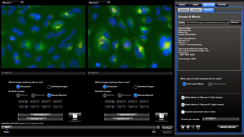
About This Guide

Audience             This user guide is for laboratory staff operating, maintaining, and analyzing data
                     using the EVOS® FL Auto Imaging System.

Revision history
                      Revision          Date                              Description
                                                     •   Updated objective calibration procedure
                         C.0          July 2014      •   Updated user interface screenshots
                                                     •   Added Movies section
                                                     •   Added French translation of Biological Hazard
                         B.0       December 2013         Safety
                                                     •   Added product warranty disclaimer
                                                     • Added EVOS® Onstage Incubator section
                         A.0      November 2013
                                                     • Updated user interface screenshots
                         1.0         April 2013      Establish new user guide

User attention       Two user attention words appear in Life Technologies user documentation. Each
words                word implies a particular level of observation or action as described below.

                            Note: Provides information that may be of interest or help but is not
                            critical to the use of the product.

                            IMPORTANT! Provides information that is necessary for proper
                            instrument operation, accurate installation, or safe use of a chemical.

Safety alert words   Four safety alert words appear in Life Technologies user documentation at points
                     in the document where you need to be aware of relevant hazards. Each alert
                     word—IMPORTANT, CAUTION, WARNING, DANGER—implies a particular
                     level of observation or action, as defined below:

                            IMPORTANT! – Provides information that is necessary for proper
                            instrument operation, accurate installation, or safe use of a chemical.

                            CAUTION! – Indicates a potentially hazardous situation that, if not
                            avoided, may result in minor or moderate injury. It may also be used to
                            alert against unsafe practices.

                            WARNING! – Indicates a potentially hazardous situation that, if not
                            avoided, could result in death or serious injury.

                            DANGER! – Indicates an imminently hazardous situation that, if not
                            avoided, will result in death or serious injury. This signal word is to be
                            limited to the most extreme situations.

                                                                                                          3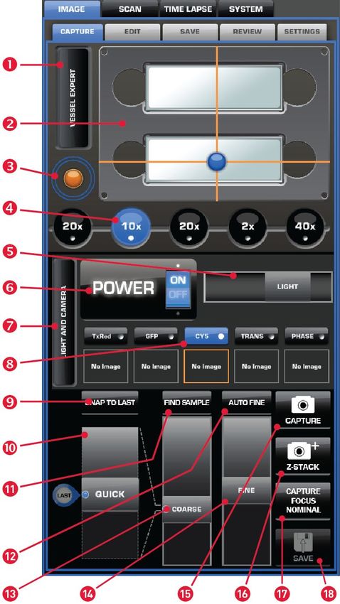
1. Installation

Standard Items Included
              Before setting up the EVOS® FL Auto Imaging System, unpack the unit and
              accessories and verify all parts are present. Contact your distributor if anything is
              missing.

                     Note: If you do not have your distributor information, contact Technical
                     Support (see page 83).

              •   EVOS® FL Auto Imaging System
              •   Computer
              •   Touch-screen monitor
              •   Keyboard
              •   Mouse
              •   Light cubes, as ordered
              •   Objectives, as ordered
              •   Vessel holder(s), as ordered
              •   Light box with cover
              •   Light cube tool
              •   Sliders: Block slider, Diffuser slider
              •   Dustcover
              •   USB flash drive (includes User Guide and Quick Start Guide)

Operating Environment
              •   Place the EVOS® FL Auto Imaging System on a level surface away from
                  vibrations from other pieces of equipment.
              •   Allow at least 5 cm (2 in) free space at the back of the instrument to allow for
                  proper ventilation and prevent overheating of electronic components.
              •   Set up the EVOS® FL Auto Imaging System away from direct light sources,
                  such as windows. Ambient room lighting can enter the imaging path and
                  affect the image quality.
              •   Operating temperature range: 4°–32°C (40°–90°F).
              •   Relative humidity range: 30–90%.

                     IMPORTANT! Do not position the instrument so that it is difficult to turn off
                     the main power switch located on the right side of the instrument base (see
                     page 58). In case of an instrument malfunction, turn the main power switch to
                     the OFF position and disconnect the instrument from the wall outlet.

4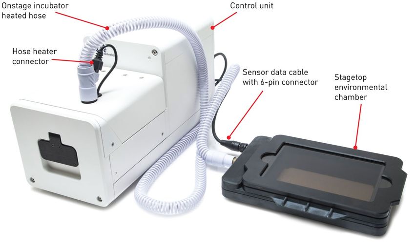
Set Up
Unpack the monitor 1. Open the case and remove the monitor and accessories.
                     2.   If a VGA cable is attached to the monitor, take it off.
                     3.   Remove protective covering from monitor.
                     4.   Plug power cord into monitor.
                     5.   Plug USB touch screen cable into monitor.

Unpack the           1.   Open the box and remove the keyboard.
computer             2.   Unpack the keyboard from its box.
                     3.   Unpack the computer.
                     4.   Unpack the mouse and power cord from the accessory holder.
                     5.   Plug in mouse, keyboard, and power cord.
                     6.   Plug the USB cord already connected to the monitor into the computer.

                              IMPORTANT! Wiping the computer supplied with the EVOS® FL Auto
                              Imaging System (i.e., erasing the hard drive to remove all programs, files,
                              and the operating system) voids the product warranty.

Unpack the           1.   Open the box and remove the accessory box.
instrument           2.   Carefully lift the instrument out of the box, holding it by one of the four
                          handholds in the base (see page 58).

                              IMPORTANT! Do not lift the EVOS® FL Auto Imaging System by stage or
                              condenser arm. Lift the instrument by using the handholds in the base.

                     3.   Place the instrument on a flat, level surface that will be free from vibration
                          and leave enough room around it for the stage to move freely.
                     4.   Remove the following from the accessory box (located in the instrument box):
                          •   Power cable
                          •   Power supply
                          •   Display Port to DVI cable
                          •   USB type A to B cable
                          •   White cardboard box (contains the light box and vessel holders)
                          •   Dust cover
                     5.   Confirm that the power switch is OFF (located on the right side of the
                          instrument base; see page 58).
                     6.   Plug the power cable into the power supply and check for the light on the
                          power supply.
                     7.   Plug the power supply connector into the instrument.
                     8.   Use the Display Port-to-DVI cable to connect the Display Port output on the
                          computer to the DVI input on the monitor.
                     9.   Use the USB cable to connect the instrument to the computer.

                              Note: At this point, everything should be plugged in and OFF. Save the
                              packaging for future shipping/storage of the instrument.

                                                                                                            5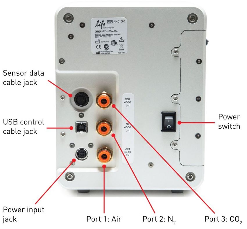
Remove the The shipping restraint prevents the X-Y stage from moving during shipping. If the
shipping restraint stage is not secured during shipping, shock and vibration can damage the motors
that move the stage. The shipping restraint must be removed before the EVOS® FL
Auto Imaging System is powered on.
1. Unscrew the three thumb screws until they spin freely. You do not need to
remove them from the shipping restraint altogether.
2. Gently pull the shipping restraint forward, away from the unit.
Note: Store the shipping restraint in your accessories box for future use. To
reinstall the shipping restraint, see page 53.
IMPORTANT! Do not subject the EVOS® FL Auto Imaging System to
sudden impact or excessive vibration. Handle the instrument with care to
prevent damage.
Turn ON the 1. Turn the instrument power switch located on the right side of the instrument
EVOS® FL Auto base (see page 58) to the ON position.
Imaging System The automatic X-Y stage will begin to move within a few seconds of the
instrument being powered on.
2. Turn the computer and monitor ON.
3. When the computer shows the Windows® desktop and the X-Y stage of the
instrument has stopped moving, click the EVOS® logo next to the start button
on the desktop to start the EVOS® FL Auto software.
4. The EVOS® loading screen will be displayed while the software is starting up.
This may take a minute.
5. Once the Image Capture tab (i.e., the Capture tab under Image, see page 7) is
displayed, the EVOS® FL Auto Imaging System is ready to use.
6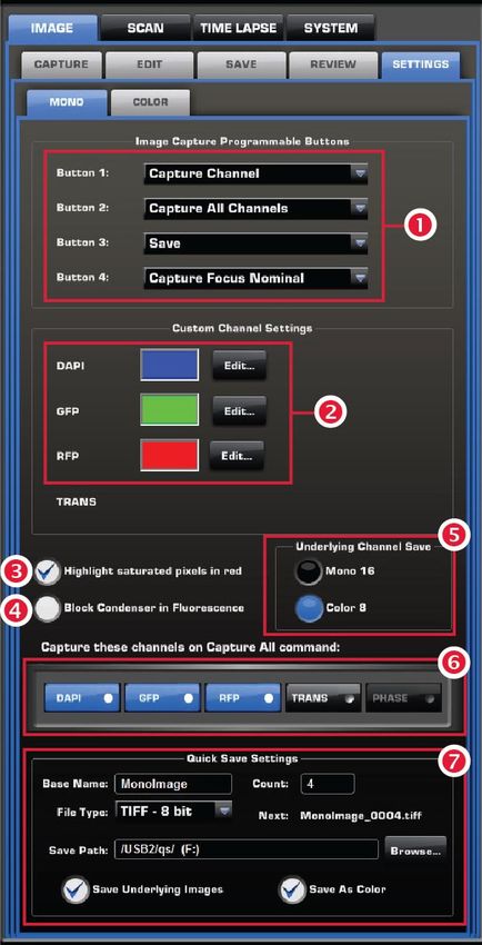
2. Basic Operation
The EVOS® FL Auto Imaging System is a fully automated imaging system
controlled by the integrated EVOS® FL Auto software. The software, accessed by
the touch-screen monitor or the mouse, controls the automated X-Y axis stage and
the objective turret, and features imaging and analysis tools.
Image Capture
Select the Image Capture tab (i.e., the Capture tab under Image) on any screen to
access” Capture Controls”. Note that the Image Capture tab is the default screen
after start-up.
Capture tab
controls
Vessel Expert button
Virtual vessel
Medium Jog button
Objective buttons
Light intensity slider
Power toggle
Light and Camera button
Light channel buttons
Snap to Last button
Quick focus slider
Find Sample button
Auto Fine button
Coarse focus slider
Fine focus slider
Capture button
Z-Stack button
Capture Focus Nominal
button
Save button
Note: , , , and are “Hot buttons”. Hot buttons are user-specified,
programmable buttons that customize the imaging system for your specific
needs. For more information on customizing Hot buttons, see page 21.
7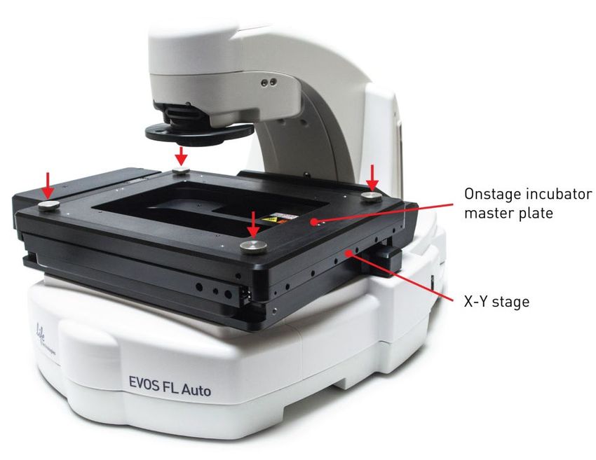
Vessel Expert       Vessel Expert button opens the Vessel
button              Selection Wizard, which is used for selecting
                    the sample vessel category (such as well
                    plate, Petri dish, culture flask, chamber
                    slide, etc.) and vessel type (such as 24-well
                    plate, 35-mm Petri dish, T75 flask, etc.) from
                    the Category       and Type       drop-down
                    menus.
                    With appropriate vessel holders, the EVOS®
                    FL Auto Imaging System can accommodate
                    a wide variety of common culture vessels
                    types in standard sizes.
                    Note that a vessel MUST be selected prior
                    to imaging.

                           Note: For a list of the vessel holders and stage plates available for the EVOS®
                           FL Auto Imaging System, refer to www.lifetechnologies.com/evosflauto or
                           contact Technical Support (page 83).

Virtual vessel      Virtual vessel is a graphical representation of the
                    sample vessel as selected with the Vessel Expert.
                    •   To choose the location on the sample vessel
                        you wish to view and image, click and drag
                        the crosshairs to the corresponding location on
                        the virtual vessel.
                    •   Click on a well to move the crosshairs to the
                        center of the well.

Medium Jog button   Medium Jog button moves the stage at an intermediate pace while viewing
                    sample, allowing the quick scanning of the sample in different parts of the sample
                    vessel.

Objective buttons   Objective buttons control the active objective turret position. The magnifications
                    displayed on the Image Capture tab reflect the objective profiles chosen on the
                    System Service tab.

Power toggle        Power toggle turns the LED light source in the selected channel ON and OFF.

Light channel       Light channel buttons are used for selecting the desired channel from the number
buttons             of installed LED light cubes or the transmitted light from the condenser. The
                    selected channel is indicated by the blue color of the corresponding Light channel
                    button.

                           Note: If there are images in the memory buffers, they will be displayed as
                           thumbnails below the corresponding light cube indicators.

8
Light and Camera Light and Camera button opens the Light
button and Camera selection tool for the
Monochrome camera (for fluorescence
and brightfield) or the Color camera
(for brightfield only).
Apply Pseudo Color allows the display
of the images in user-defined pseudo color
(see page 21) when using the Monochrome
camera in fluorescence channels.
Note: While pseudo colors help differentiate the channels used in multi-
channel overlays, grayscale images usually show more detail.
Actual Mode allows you to individually adjust the LED intensity, camera gain,
and exposure (rather than controlling them as a single parameter with the Light
Intensity slider).
Clear All Channels clears out all memory buffers, which are temporary
holding areas for captured images.
Snap to Last button Snap to Last button reverts to the focus position of the last captured image.
Quick slider Quick slider moves the focus through a small subset of the total focal range as
determined by the current vessel. This focal range is centered around the “Focus
Nominal” of the selected vessel (see Hot buttons, below). Utilizing the Quick
slider reduces the need to use the Find Sample button and the Coarse Focus slider.
Find Sample and Find Sample and Auto Fine Buttons are used for automatic coarse and fine
Auto Fine buttons focusing on the sample.
Coarse and Fine Coarse and Fine Focus sliders are used to manually adjust coarse and fine focus.
Focus sliders
Hot buttons “Hot buttons” are user-specified, programmable buttons that customize the imaging
system. Up to four Hot buttons can be displayed on the Image Capture tab. For
detailed information on customizing Hot buttons to your specific needs, see page 21.
Capture images 1. Place the vessel containing your sample on the stage using the appropriate
using the Capture vessel holder. For the types of vessel holders available for the EVOS® FL Auto
Imaging System, refer to www.lifetechnologies.com/evosflauto or contact
tab
Technical Support (page 83).
2. Use the Capture tab controls to select the desired imaging options (such as
vessel type, area to capture, lighting, magnification, etc.) and adjust the
illumination and the focus.
3. Click the desired Capture button to acquire your image.
4. Click Save Image to save the image to the desired location (see page 10).
9Save
Clicking the Save Image button on any screen opens the Image Save tab, which
allows you to name and save an image file or a scan in a desired location in a USB
drive or the network, and to choose the desired Save Options.
Save tab controls Folder address bar : Describes the
location of the current folder or the file.
Up folder button : Navigates up to a
higher-level folder.
New folder button : Creates a new
folder in the current location.
Current folder : Contains lower
lever folders and/or saved files. Click
on the lower level folders to navigate
there.
File Name text field : Allows you to
enter a file name for your image.
Save Options : Allows you to save
your image using the Default,
Quantitative Monochrome, or Custom
options.
Bit Depth : Allows you to set you
color depth to 8-bit (256 colors) or
16-bit (thousands of colors; high-color).
File Type drop-down menu :
Allows you choose the format of your
saved image file. Available options are
JPEG, BMP, TIFF, and PNG.
Save As : Allows you to choose
between Color or Monochrome.
Include Image Annotations : Allows
you to include image annotations in
your saved image.
Save Underlying Channels : Allows you to include the underlying channels in
your saved image.
Save Image : Saves your image using the selected options.
Note: The Default option saves images in 8-bit color in TIFF format with
the image annotations included.
To save a 16-bit image, select TIFF, and ensure that the Color option is
deselected.
File types JPEG and PNG (as well as images of all types with the Color
options engaged) only save at 8-bit depth.
103. Edit and Analyze Images
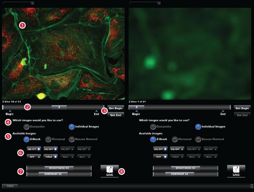
Overlay
The Image Edit Overlay tab allows further adjustments to the brightness and
contrast in each channel before the captured image is saved. Each channel can be
turned ON and OFF independently and the brightness and contrast for each
channel can be adjusted separately using controls described below.
Overlay tab ON/OFF buttons : Toggle the display
controls of corresponding channel in the overlay.
Light channel buttons : Select the
light channel for adjusting the
brightness and contrast. The channel
being adjusted is indicated by the blue
color of the corresponding button. In the
example on the right, the RFP channel is
selected for adjustment.
Brightness and Contrast sliders :
Adjust the brightness and contrast of the
image in the selected channel.
Reset All Channels : Returns the
brighness and contrats settings to their
previous value.
Clear Channel : Clears the memory
buffer for the selected channel.
Save Image : Saves the image in the
desired location. For more information,
see page 10.
Note: Captured images can be saved in JPEG, BMP, TIFF, and PNG
formats. For more information and additional save options, see page 10.
11Measure
The Image Edit Measure tab is used for adding annotations, creating
histograms for visualizing data, and drawing up to 12 regions of interest (ROIs) in
the captured image prior to saving.
Measure tab Picture
controls Current Image : Selects an image from
memory buffer to annotate.
Annotations
Add : Activates the Add mode to add
an annotation using the Annotation tools
(see below).
To add an annotation, click Add, select an
Annotation tool , and then click the
area of the image where you want to add
the annotation.
Select : Activates the Select mode to
edit the properties of an existing
annotation or the contents of a text box.
Zoom : Activates the digital zoom
function onscreen, allowing a closer look
at live or captured images.
To zoom on an image, click Zoom, and
then double-click the area on the screen
you wish to enlarge. To restore the view
to unzoomed magnification, right-click
anywhere on the image
Annotation Tools : Include the text
box, arrow, histogram, rectangle, ellipse,
and line tools.
If there is no keyboard connected to the
system, a virtual keyboard will appear
when adding or editing a text box.
Annotation properties
Name : Allows you to label the annotation that you have added.
Color Edit : Allows you to select the color of an annotation.
Measure : Selects what is measured in a region of interest (ROI).
Lock Aspect Ratio : Locks the aspect ratio of the selected annotation tool.
Width : Changes the line width of the selected annotation.
Delete Selected : Deletes selected annotations.
Edit Text : Allows you to edit existing text in a selected text box.
Plot : When an intensity plot is displayed for a line, allows you to shades the
area under each line.
Smooth : Smooths the histogram plot.
12Misc.
Show Annotations : Option to display or hide the annotations on screen.
Save Image as Screenshot : Option for saving the image shown onscreen as its
own file.
Show Annotation after Add : Option to edit annotations as they are added.
Units : Selects the units of measurement used for the annotations.
Show Histogram/Instensity : Option to display or hide the histogram for a
selected ROI. If the line tool is selected, an intensity plot is displayed instead of a
histogram. Histogram/intensity data include information from underlying channels
if the ROI is selected using images from Image Capture, but not from Image Review.
Delete All Annotations : Deletes all existing annotations.
Export All : Exports histogram/intensity data, including underlying channel
data when coming from Image Capture, as a .csv file. When coming from Image
Review, underlying channel data are not included.
Save Image : Saves the image and the annotation(s) as a single file. For more
information, see page 10.
Note: All annotations will remain whether or not a new image is captured.
To start over, click Delete All Annotations .
13Count
Count tool The Count tool, located in the Image Edit Count tab, allows you to manually
mark items onscreen using up to six separate labels. As you tag each item to assign
one of the six labels (thus grouping similar items together), the system keeps a
running tally of the counts with percentages for each label assigned.
Note: You can use the Count tool on both newly captured and saved
images, and document the results of your count by saving the tagged
image, with the Count tool displaying the totals.
Count tool controls Tags
Add : Activates the Add mode to tag
items onscreen using the selected Label
(see below).
Select : Activates the Select mode to
select existing tags onscreen.
Zoom : Activates the digital zoom
function for a closer look at live or
captured images.
Labels : Select the label used for
tagging on-screen items. Each label row
features a text field for entering a label
name and displays arunning tally of
the count with percentage . Clicking in
the trash bin icons deletes the tags on the
screen for that label set.
Total : Displays the total count of all
labels assigned.
Misc.
Delete All Tags : Deletes all existing
tags.
Show Tags : Displays or hides the tags
onscreen.
Show Grid : Displays or hides the
onscreen counting grid.
Grid size : Selects the grid size from a drop-down menu.
Save Image as Screenshot : Option to save the image as displayed in the Count
tool, showing the labels, counts, and percentages. Deselecting this option produces
an image saved with the tags only.
Save Image : Saves the image in the desired location.
Note: You can document the results of your count by saving the tagged
image with the Save Image as Screenshot option selected; this will save
the image showing the labels, counts, and percentages as displayed in the
Count tool.
14Count procedure 1. Begin by acquiring an image in the Capture tab (see page 9) or by opening a
saved image using the Review tab (see page 18).
2. Click Show Grid and choose Grid size from the drop-down menu. You may
also choose to leave this option inactive.
3. Click the text field next to a label to enter a name for that label category.
Repeat for the remaining labels, as necessary. You can use up to six labels per
count.
4. To begin counting, click Add to activate the Add mode.
5. Select a Label button, and then left-click at each point onscreen to tag the
items for that category. Each tagged item will show the label used, and a
running tally of the count with the percentage for the label used and the total
count will be displayed in the Count tool.
Note: You may switch labels as desired during a count; the EVOS® FL
Auto software will tag each item for the label selected.
6. To use digital zoom while counting, click Zoom to select the Zoom mode, and
then double-click the area onscreen you wish to enlarge. To resume counting,
click Add to reselect the Add mode.
7. To move a tag, click Select to activate the Select mode, and then click and drag
the tag to the desired location. Left-click anywhere on the screen to deselect it.
8. To delete a tag, right-click it. You may also click Delete All Tags to delete all
tags for all labels.
9. To save the image with the tags, showing the labels, counts, and percentages
as displayed in the Count tool, select Save Image as Screenshot, and then
click Save Image to save the image in the desired location.
Note: Deselecting the Save Image as Screenshot option will produce an
image saved with the tags only.
15Auto Count
Auto Count tool The Auto Count tool, located in the Image Edit Auto Count tab, is used for
automatic counting of regions of interest (ROI) on an image.
Based on a histogram of the captured image and gated by signal intensity, the tool
uses an algorithm to mark and count the regions of interest (ROI) on the screen
(see the example below).
Auto Count controls Count : Initiates the Auto Count
procedure for the captured or live
image on the screen.
Count From File : Opens a
previously saved image to perform
Auto Count.
Separate touching cells : Option to
separately count the cells that are
touching, which increases the accuracy
of the count.
Aggressive boundaries : Option to
more aggressively tighten the
boundaries around regions, resulting in
more ROI.
Count field : Displays the results of
the count (i.e., the number of ROI on
the screen above the signal threshold).
Brightness : Controls the sensitivity
of the Auto Count tool by changing the
threshold for brightness.
Area : Controls the sensitivity of the
Auto Count tool by changing the
threshold for area. Increasing the area
threshold causes only larger cells to be
counted, while decreasing it allows a
wider range for the cell size.
Circularity : Controls the sensitivity
of the Auto Count tool by changing the
threshold for circularity.
Show cells : Displays the counted objects outlined in green to help you
optimize the parameters used for object segmentation and counting.
Save Image as Screenshot : Option to save the image as displayed in the Auto
Count tool, showing the labels, counts, and percentages. Deselecting this option
produces an image saved with the tags only.
Save Image : Saves the image in the desired location.
16Auto Count 1. Begin by acquiring an image using the Capture tab (see page 9).
procedure 2. Go to the Auto Count tab, and then click Count to initiate the Auto Count
procedure.
Alternatively, click Count From File to perform the Auto Count procedure on
a previously saved image.
3. Based on a histogram of the captured image, the EVOS® FL Auto software will
use an algorithm to mark and count the regions of interest (ROI) on the screen
(see the example below). The result of the count (i.e., the number of ROI on the
screen above the signal threshold) is displayed in the Count field.
4. Select Show cells to visualize the boundaries used by the software to mark
and count the ROI during the count.
5. Review the ROI marked on the screen and select Separate touching cells and
Aggressive boundaries options, if desired. Separately counting the cells that
are touching increases the accuracy of the count and aggressively tightening
the boundaries around regions results in more ROI to be counted.
6. Adjust the sensitivity of the count by moving the Brightness and Area sliders
in the 100% or 0% direction. This changes the thresholds for brightness and
area, respectively, to be designated as ROI and included in the count.
Note: Moving the slider in the 100% direction increases the count sensitivity
by lowering the threshold above which the ROI are counted and results in a
greater number of ROI and a higher count; moving it in the 0% direction
increases the threshold value, thereby reducing sensitivity and lowering the
count.
7. Adjust the threshold for circularity by moving the Circularity slider in the
high or low direction.
8. To save the image with the tags, select Save Image As Screenshot, and then
click Save Image.
17Image Review
The Image Review tab utilizes a folder system for easily locating saved files and
allows you to review still images or play video files from the USB drive or the network
connection. You may also use this tab to rename or delete saved files.
Review tab controls Folder address bar : Describes the
location of the current folder or the file.
Up folder : Navigates up to a higher-
level folder.
Create folder : Creates a new folder in
the current location.
Current folder : Contains lower lever
folders and/or saved files.
Selected file : Displays the name and
date of creation for the selected file.
Rename : Allows you to rename the
selected file.
Delete : Deletes the selected file.
Reuse : Recalls settings from image
file and applies them to the microscope,
including vessel selection, XY position,
focus position, objective, light channel,
and light slider settings.
Save Image : Saves the image in the
desired location. For more information,
see page 10.
184. Advanced Operations
Image Settings
The Image Settings tab allows you to customize the user interface of the EVOS®
FL Auto Imaging System for your specific needs. Select Image Settings Mono
tab to customize the settings for the Monochrome camera or select Image
Settings Color for the Color camera.
Image settings for Image Capture Reprogrammable
monochrome Buttons : Assign up to four user-
programmable image capture buttons
camera
(i.e., “Hot buttons”) to be displayed on
the Image Capture Mono tab (see
page 21).
Custom Channel Settings : Applies
a pseudo color to each channel to help
differentiate the images in multi-
channel overlays when using the
Monochrome camera.
Highlight Saturated Pixels in Red :
Option to display pixels in saturated
areas on a live image in red so that the
LED intensity, gain, and exposure time
can be adjusted individually in the
Actual mode (page 9) or together by
using the Light intensity slider
(page 7).
Block Condenser in Fluorescence :
Moves the condenser to blocking
position when fluorescence channel is
selected. This can improve fluorescence
captures when light box is not used
over the sample, but it can significantly
increase the time it takes to change
channels and objectives. Not
recommended for most users.
Underlying Channel Save : Allows
you to save the underlying channel in 8-bit color (256 colors) or 16-bit
monochrome.
Capture All selection : Assigns the channels captured with the Capture All
button.
Quick Save settings : Determines the Quick Save settings, such as base name,
file type, save path, and the options for saving the underlying images and color.
19Image settings for Image Capture Reprogrammable
color camera Buttons : Assigns up to four user-
programmable image capture buttons
(i.e., “Hot buttons”) to be displayed on
the Image Capture Color tab (see
page 21).
Adjust color : Contains slider controls
that adjust color settings (Brightness,
Contrast, Saturation, Hue) for all future
captures using the Color camera.
Reset : Resets the color settings to
default values.
Highlight Saturated Pixels in Red :
Option to display pixels in saturated
areas on a live image in red so that the
LED intensity, gain, and exposure time
can be adjusted individually in the
Actual mode (page 9) or together by
using the Light intensity slider (page 7).
Quick Save settings : Determines the
Quick Save settings, such as base name,
file type, and save path.
20Assign Hot buttons 1. To assign up to four user-programmable image capture buttons (i.e., Hot
buttons) to be displayed on the Image Capture tab, click the Mono or Color
tab under Image Settings Color to select the camera for which you wish to
apply the Hot buttons.
2. Select up to four Hot buttons from the drop-down menus under Image
Capture Reprogrammable Buttons in the order you want them displayed
(Buttons 1–4).
You can choose from the following options:
• Capture: Captures the current image on the screen.
• Capture All: Captures an image using each of the installed light cubes.
• Transfection: Creates a two-image overlay using one fluorescent image
and one transmitted light image.
• Save: Saves the captured images.
• Z-Stack: Captures a series of images of the sample along the z-axis.
• Capture Focus Nominal: Sets the focus nominal for the current vessel.
Focus nominal is the Z-point, around which the focal range of the Find
Sample autofocus and the Quick slider is centered.
• Quick Save: Allows single-click saving of captured images. There are
separate monochrome and color settings for Quick Save, which can be
accessed via the Image Settings tab.
Select pseudo When using the Monochrome camera in multi-channel overlays, applying a
colors pseudo color to each channel helps differentiate the images. To assign a custom
pseudo color to a channel, follow the procedure below.
1. In Image Settings, select the Mono tab for the Monochrome camera.
2. Under Custom Channel Settings, click Edit for the desired channel, then
select the color you wish assign.
3. Repeat for the remaining channels.
Note: While pseudo colors help differentiate the channels used in multi-
channel overlays, grayscale images usually show more detail.
21Scan
The Scan tab gives you the option to create and recall “scan routines”, a series of
steps to acquire a tiled and stitched image. For repeat experiments, Scan routines
can be saved, recalled, even edited.
Routines tab The Scan Routines tab is used for
controls creating and running new scan routines,
and running, editing, and deleting
existing routines.
Create New Routine : Initiates the
Scan Wizard to guide you through a
series of steps to create, save, and run a
new scan routine based on your
specifications.
Folder : Describes the location of the
current folder or routine.
Up folder : Navigates up to a higher-
level folder.
Create folder : Creates a new folder in
the current location.
Stored list : Contains lower lever
folders and/or saved routines.
Run : Runs the selected routine.
Edit : Allows you to change the
parameters of an existing routine.
Delete : Deletes the selected routine.
Create a scan 1. Go to Scan Routines tab, and then click Create New Routine to open the
routine Scan Wizard.
The Scan Wizard will guide you through the process of creating your own
scan routine as you make a series of onscreen selections.
After making your selection at each step, click Next
for the next prompt or click Back to revisit the
previous step. Click Cancel to abort the process.
Note: To have the option of changing a step of a saved scan routine any
time you recall and run the scan, select the Show this page again option at
the bottom of the page you wish to revisit.
222. When prompted, enter the routine name and select a Vessel from the list.
Selected vessel type will be highlighted in blue and a virtual vessel will
appear under the list (in the example below, a dual slide holder is selected).
3. Select the objective, camera, and the desired light channels to use in your
scan routine.
4. If desired, select Save the individual lighting channel images separately.
Note that saving images separately requires more disk space.
5. When prompted, choose how to select the areas you would like to cover in
your scan. You have two options:
• Select area rectangle: Move and size a “region of interest rectangle” on
your virtual vessel. If using this method, continue with “Scan Routine
Options: Select Area Rectangle”, page 24.
• Place beacons on the live microscope image: Mark the opposite corners of
your area of interest on the live image to designate your area(s) of interest.
If using this method, continue with “Scan Routine Options: Place Beacons
on Live Image”, page 25.
23Scan routine 1. When prompted, choose Select area rectangle.
options: select area 2. Using the virtual vessel (vessel image representing the sample vessel), select
rectangle the wells or slides to cover in your scan (in the example below, Slide 2 in a
dual slide holder is selected).
3. Select the area of the vessel you wish to scan by moving and sizing the area
rectangle (indicated by red arrow in the example) using the Position and Size
controls.
4. Determine how often you would like the system to refocus during a scan by
selecting Find Sample and Auto Fine options for the scan.
• Find Sample: searches over a wide range to provide coarse focus.
• Auto Fine: searches over a narrow range to provide fine focus.
• You may choose to run either, both, or neither of the two focus functions
during a scan routine.
5. Select the amount of coverage. You may choose from the available coverage
options (full coverage, four points, etc.), select to enter a number of random
images, enter a percentage of the vessel to scan, or create a custom coverage
grid. A larger area requires longer scan time and results in a bigger file size.
6. When prompted, adjust focus and lighting for each of the channels that you
have selected.
7. Proceed to “Finish Creating a Scan Routine”, page 26.
24Scan routine 1. When prompted, choose Place beacon on the live microscope image and enter
options: place the number of regions you would like to define.
beacons on live 2. Click Add Beacon, and using the crosshairs on the virtual vessel, pan to your
image area of interest (in example on the right, center of Slide 2).
3. Using the crosshairs on the virtual
vessel, pan to your ROI and then
click on the live image to select the
location to add your beacon. The
beacon will be placed at the
location as determined by the
crosshairs on the live image.
• Beacon 1 determines the top
left starting position of the
scan.
• Beacon 2 determines the
bottom right of the scan.
4. To update an existing beacon,
select it from the Beacons list, make
your changes, and then click
Update Selected.
To delete an existing beacon, select it, and then click Delete Selected.
To delete all existing beacons, click Delete All.
Adjust focus and 1. After placing your beacons, adjust
lighting the focus and lighting for each of
the channels that you have
selected.
2. Determine how you would like the
system to refocus during a scan by
selecting Find Sample and Auto
Fine options for the scan.
You may choose to run either, both,
or neither of the two focus
functions during a scan routine.
• Find Sample: searches over a
wide range to provide coarse
focus.
• Auto Fine: searches over a
narrow range to provide fine
focus.
3. Click Next Channel to proceed to
the next selected light channel.
Click Prev Channel to return to the
previous light channel.
4. After you have adjusted the focus and lighting for each of the channels, click
Next to proceed to “Finish creating a scan routine”, page 26.
25Finish creating a 1. When prompted, navigate to
scan routine location in the network or the USB
drive where you wish to save the
images captured during the scan
and select the desired folder.
To create a new save folder, click
Create folder button.
2. If you wish to change the location
where the images are saved each
time you run the scan, select
Show this page again when I run the scan.
3. Click Next to proceed to the next step.
4. Click Finish to save your routine in the selected location without running it.
Alternatively, click Start to run your scan routine immediately.
Recall a saved scan The Stored list in the Scan Routines tab allows you to recall a saved scan
routine routine and run it with new samples.
1. On the Scan Routines tab (page 22), navigate to the folder containing the
saved scan routine you wish to recall.
2. Click the routine of interest in Stored list to select it. Note that the
icon for a saved scan routine is different from the folder icon
depicting saved scans, which contain the images captured during
a scan routine.
3. Click Run to run the selected routine.
Click Edit to make changes to the routine parameters.
Click Delete to delete the routine.
Note: Saved scan routines retain the information about the placement of
the beacons as well as the camera and lighting options you have selected
when creating the routine. You can change these routine parameters by
clicking Edit after selecting the scan routine of interest from the Stored list.
Edit a scan Use the Scan Edit tabs (Overlay, Measure, and Count) to edit your scans.
The controls for editing scans are identical to the controls used for editing single
captured images in Image Edit tabs.
Refer to “Edit and Analyze Images” on page 11 for detailed information on using
these tools.
26Export a scan Scans are saved as “.sti” files, which are very large. To make scans more user-
friendly, you have the option of exporting the scan using a different image quality.
You may also use the digital zoom to select a specific area of the image and then
export that particular part of the screen.
1. Go to Scan Edit tab.
2. In Save Settings, select desired
Quality (Low, Medium, or
High). The export tool will
display the resolution and
approximate size of the
selected option.
3. Click Export Scan to save it in
the quality selected.
Review a scan The Scan Review tab utilizes the same folder system as the Image Edit tab
(page 18) for easily locating saved files. It also allows you to review still images or
play video files from the USB drive or the network connection. You may also use
this tab to rename or delete saved files.
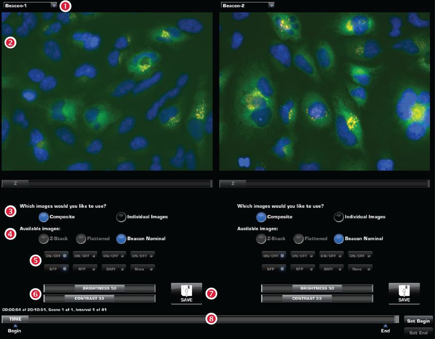
27Time Lapse
The Time Lapse tab gives you the option of creating and running a time lapse
routine. A time lapse routine automatically captures individual images of a region
of interest (ROI) at given intervals over a time period based on your specifications.
The images can then be stitched together into a video.
You will first specify the conditions for the entire “movie” (e.g., image capture
options, ROI), and then you will build “scenes” that determine the overall length
of the routine and environmental conditions along the way.
Routines tab The Time Lapse Routines tab is used
controls for creating and running new time lapse
routines, and running, editing, and
deleting existing routines.
Create New Routine : Initiates the
Scan Wizard to guide you through a
series of steps to create, save, and run a
new scan routine based on your
specifications.
Folder : Describes the location of the
current folder or routine.
Up folder : Navigates up to a higher-
level folder.
Create folder : Creates a new folder in
the current location.
Stored list : Contains lower lever
folders and/or saved routines.
Run : Runs the selected routine.
Edit : Allows you to change the
parameters of an existing routine.
Delete : Deletes the selected routine.
Create a time lapse 1. Go to Time Lapse Routines tab, and then click Create New Routine to open
routine the Scan Wizard.
The Scan Wizard will guide you through the process of creating your own
scan routine as you make a series of onscreen selections.
After making your selection at each step, click Next
for the next prompt or click Back to revisit the
previous step. Click Cancel to abort the process.
Note: To have the option of changing a step of a saved scan routine
any time you recall and run the scan, select the Show this page again
option at the bottom of the page you wish to revisit.
282. When prompted, enter the routine name and select a Vessel from the list.
Selected vessel type will be highlighted in blue and a virtual vessel will
appear under the list (in the example below, a dual slide holder is selected).
3. When prompted, enter the name of
the routine and the number of
scenes.
4. Select the objective, camera
(monochrome or color), and the
light channels to use in your time
lapse routine.
5. If desired, select to use the Auto
find sample, Auto fine focus, Z-
Stack, and Auto lighting options.
The Auto find sample and Auto
fine focus options also allow you
select the channels on which to run
these options.
• Auto find sample searches
over a wide range to provide
coarse focus to your sample
during the time lapse routine.
• Auto fine focus option
provides fine focus over a
narrow range.
• Z-Stack option captures a series
of images along the z-axis.
6. Click Next to proceed to setting
beacons (page 30).
29Set beacons 1. Click Add Beacon to manually place
the beacons to determine your area
of interest.
Unlike a scan routine, where you can
add only two beacons, you can add
up to 384 beacons in a time lapse
routine.
2. Using the crosshairs on the virtual
vessel, pan to your ROI and then
click on the live image to select the
location to add your beacon. The
beacon will be placed at the location
as determined by the crosshairs on
the live image.
3. Alternatively, click Populate Wells
to automatically place a beacon at
the center of each well of the
selected culture vessel.
4. To update an existing beacon, select
it from the Beacons list, make your
changes, and then click Update
Selected.
To delete an existing beacon, select
it, and then click Delete Selected.
To delete all existing beacons, click
Delete All.
5. After placing your beacons, adjust
the focus and lighting for each of the
channels that you have selected.
6. Enter the time lapse options (e.g., option to create video for each beacon,
whether to include watermarks, and whether to save individual channels).
Create scenes 1. When prompted, enter length of
scene and capture interval.
2. Select Capture one frame only to
capture images on each beacon only
once and then end the routine. This
option is available only if you have
specified a single scene.
3. Next, enter the culture conditions
in the environmental chamber
conditions (e.g., temperature,
humidity, atmosphere).
4. If desired, add additional scenes and
enter the desired conditions for each
scene.
5. After setting up all the scenes, click Next to proceed to “Finish creating a time
lapse routine”, page 31.
30Finish creating the 1. When prompted, navigate to
time lapse routine location in the network or the USB
drive where you wish to save the
images captured during the scan
and select the desired folder.
To create a new save folder, click
Create folder button.
2. If you wish to change the location
where the images are saved each
time you run the scan, select Show
this page again when I run the scan.
3. Click Next to proceed to the next step.
4. Click Finish to save your routine in the selected location without running it.
Alternatively, click Start to run your time lapse routine immediately.
Run the time lapse 1. To run the time lapse routine, click
routine Start.
2. To adjust the parameters for the
time lapse routine anytime during a
run, click Pause and adjust the
desired parameters (see page 32).
Click OK to resume the routine.
3. Click Show “In Progress” page to
view the captured images and the
progress of the time lapse routine.
4. Click Stop to abort the time lapse
routine.
31Recall a saved time The Stored list in the Routines tab allows you to recall a saved scan routine and
lapse routine run it with new samples.
1. On the Time Lapse Routines tab (page 28), navigate to the folder containing
the saved scan routine you wish to recall.
2. Click the routine of interest in the Stored list to select it. Note that
the icon for a saved time lapse routine is different from that of the
time lapse folder, which contains the images captured during a
time lapse routine.
3. Click Run to run the selected routine.
Click Edit to make changes to the routine parameters.
Click Delete to delete the routine.
Note: Saved time lapse routines retain the information about the placement
of the beacons as well as the camera and lighting options you have selected
when creating the routine. You can change these routine parameters by
clicking Edit after selecting the scan routine of interest from the Stored list.
Edit a saved time 1. To edit a saved time lapse routine, select the routine of interest from the
lapse routine Stored list and click Edit.
2. Edit the desired conditions for the routine, using the same procedures as
described for creating a routine (page 28), setting beacons (page 30), and
creating scenes (page 30).
You can change the image capture options, add or delete beacons, change
scene options (e.g., length of a scene, the capture interval etc.), as well as
modifying the culture conditions (e.g., temperature, humidity, atmosphere).
3. Click Finish to save your routine in the selected location without running it.
Alternatively, click Start to run the edited time lapse routine immediately.
Adjust routine You can adjust the parameters for a time lapse routine anytime during a run. This
parameters allows you to quickly fine-tune your time lapse routine in response to changing
experimental or culture conditions. In contrast to editing a routine, which saves
the changes made, adjustments made to the routine parameters during a time
lapse run do not persist after the run is completed.
1. To adjust the parameters for a time lapse routine anytime during a run, click
Pause.
2. Adjust the desired conditions for the routine, using the same procedures as
described for setting beacons and creating scenes (page 30).
3. Click OK to resume the routine.
Review a time lapse The Time Lapse Review tab utilizes the same folder system as the Image Review
tab (page 18) for easily locating saved files. It also allows you to review still images
or play video files from the USB drive or the network connection. You may also use
this tab to rename or delete saved files.
32You can also read