Mission Concept Study - The National Academies of ...
←
→
Page content transcription
If your browser does not render page correctly, please read the page content below

National Aeronautics and Space Administration

Mission Concept Study

                       Planetary Science Decadal Survey
                        Mars 2018 MAX-C Caching Rover

            Science Champion: Raymond E. Arvidson (arvidson@rsmail.wustl.edu)
                                                 NASA HQ POC: Lisa May (lisa.may@nasa.gov)

                                                                                  March 2010
 www.nasa.gov
Mars 2018 MAX-C Caching Rover                                                                  1
Data Release, Distribution, and Cost
Interpretation Statements
This document is intended to support the SS2012 Planetary Science Decadal Survey.
The data contained in this document may not be modified in any way.
Cost estimates described or summarized in this document were generated as part of a preliminary
concept study, are model-based, assume a JPL in-house build, and do not constitute a commitment on
the part of JPL or Caltech. References to work months, work years, or FTEs generally combine multiple
staff grades and experience levels.
Cost reserves for development and operations were included as prescribed by the NASA ground rules for
the Planetary Science Decadal Survey. Unadjusted estimate totals and cost reserve allocations would be
revised as needed in future more-detailed studies as appropriate for the specific cost-risks for a given
mission concept.

Mars 2018 MAX-C Caching Rover                                                                              i
Planetary Science Decadal Survey
Mission Concept Study Final Report

Acknowledgments......................................................................................................... v

Executive Summary ..................................................................................................... vi

1.       Scientific Objectives ............................................................................................ 1
Science Questions and Objectives ............................................................................................... 1
Science Traceability ...................................................................................................................... 3

2.       High-Level Mission Concept ............................................................................... 5
Overview ....................................................................................................................................... 5
Concept Maturity Level ................................................................................................................. 5
Technology Maturity...................................................................................................................... 6
Key Trades .................................................................................................................................... 7

3.       Technical Overview .............................................................................................. 8
Strawman Instrument Payload Description ................................................................................... 8
Flight System .............................................................................................................................. 15
Concept of Operations and Mission Design ................................................................................ 24
Round-Trip Planetary Protection................................................................................................. 26
Risk List ...................................................................................................................................... 27

4.       Development Schedule and Schedule Constraints ......................................... 29
High-Level Mission Schedule ...................................................................................................... 29
Technology Development Plan ................................................................................................... 30
Development Schedule and Constraints ..................................................................................... 31

5.       Mission Life-Cycle Cost ..................................................................................... 32
Costing Methodology and Basis of Estimate .............................................................................. 32
Cost Estimates ............................................................................................................................ 32

Mars 2018 MAX-C Caching Rover                                                                                                                    ii

Figures
Figure 3-1. The Proposed MAX-C SHEC Subsystem. ............................................................................... 14
Figure 3-2. The Proposed MAX-C Rover .................................................................................................... 16
Figure 3-3. Entry, Descent, and Landing .................................................................................................... 21
Figure 3-4. Risk Chart ................................................................................................................................. 28

Tables
Table 1-1. Science Traceability Matrix .......................................................................................................... 3
Table 2-1. Concept Maturity Level Definitions .............................................................................................. 6
Table 3-1.Pancam (Mast).............................................................................................................................. 8
Table 3-2. NIR Point Spectrometer (Mast).................................................................................................... 9
Table 3-3. Microscopic Imager (Arm) MI Design ........................................................................................ 10
Table 3-4. APXS (Arm) ............................................................................................................................... 10
Table 3-5. Raman Spectrometer (Arm/Body) ............................................................................................. 11
Table 3-6. Cache Sample Handling, and Container ................................................................................... 12
Table 3-7. Corer/Abrader ............................................................................................................................ 12
Table 3-8. Mast ........................................................................................................................................... 13
Table 3-9. Arm (Short, Low Pre-Load) ........................................................................................................ 13
Table 3-10. Organic Blank .......................................................................................................................... 13
Table 3-11. Proposed Payload Mass and Power ....................................................................................... 14
Table 3-12. MAX-C Mass/Power Preliminary Estimates ............................................................................ 16
Table 3-13. Proposed MAX-C Rover Characteristics ................................................................................. 17
Table 3-14. Pallet Mass and Power Preliminary Estimates ........................................................................ 18
Table 3-15. Proposed Pallet Characteristics............................................................................................... 18
Table 3-16. Descent Stage Mass and Power Preliminary Estimates ......................................................... 20
Table 3-17. Descent Stage Characteristics ................................................................................................ 20
Table 3-18. Entry System Mass and Power Preliminary Estimates............................................................ 22
Table 3-19. Entry System Characteristics................................................................................................... 22
Table 3-20. Cruise Stage Mass and Power Preliminary Estimates ............................................................ 23
Table 3-21. Cruise Stage Characteristics ................................................................................................... 23
Table 3-22. Trajectory Parameters for Each Launch Date in the Launch Period ....................................... 25
Table 3-23. Mission Design......................................................................................................................... 25
Table 3-24. Mission Operations and Ground Data Systems ...................................................................... 26
Table 3-25. Risk Level Definitions .............................................................................................................. 28
Table 4-1. High-Level Mission Schedule .................................................................................................... 29

Mars 2018 MAX-C Caching Rover                                                                                                                              iii
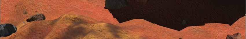
Table 4-2. Key Phase Duration ................................................................................................................... 29
Table 4-3. Technology Development Cost Profile ...................................................................................... 30
Table 5-1. Science Costs and Workforce ................................................................................................... 33
Table 5-2. Total Mission Cost Funding Profile ............................................................................................ 34

Appendices
A. Acronyms

B. Master Equipment Lists

Mars 2018 MAX-C Caching Rover                                                                                                                    iv

Acknowledgments
This report was authored by Marguerite Syvertson, Jet Propulsion Laboratory, California Institute of
Technology.
This research was carried out at the Jet Propulsion Laboratory, California Institute of Technology, under a
contract with the National Aeronautics and Space Administration.
© 2010. All rights reserved.

Mars 2018 MAX-C Caching Rover                                                                             v
Executive Summary
The proposed 2018 Mars Astrobiology Explorer-Cacher (MAX-C) caching rover would be a NASA-built
mid-class rover that would be the first component in a Mars sample return campaign strategy. NASA is
projecting to launch the proposed MAX-C rover with the European Space Agency’s (ESA’s) ExoMars
mission on a U.S.-provided launch vehicle in mid 2018; the entry, descent, and landing systems would
use the “Sky Crane” approach developed for Mars Science Laboratory (MSL) to land a pallet with both
rovers secured onboard onto the surface of Mars. After the rovers egress from the pallet, there would be
a period of checkout for both rovers. MAX-C would be designed to operate on the surface of Mars for 500
sols. The MAX-C rover suite of science instruments would be used to identify and target potential rock
samples and a sample handling, encapsulation, and caching system to obtain and preserve samples for
eventual return to Earth by a potential future Mars Sample Return mission.
Acquisition and return to Earth of martian materials has been a high science priority since the 1970s. The
proposed MAX-C would start the sequence of missions that would enable this high-priority objective to be
accomplished. The proposed scientific objectives for this mission are as follows:
At a site interpreted to represent high habitability potential, and with high preservation potential
for physical and chemical biosignatures:
evaluate paleoenvironmental conditions,
characterize the potential for the preservation of biotic or prebiotic signatures, and
access multiple sequences of geological units in a search for possible evidence of ancient life
and/or prebiotic chemistry.
Samples necessary to achieve the proposed scientific objectives of the potential future sample
return mission should be collected, documented, and packaged in a manner suitable for potential
return to Earth.
The proposed MAX-C rover would have the dual objectives of conducting high-priority in situ science and
obtaining rock samples for eventual return to Earth. To ensure access to the scientifically most interesting
samples, MAX-C would be designed to rove 20 km over a 500-sol nominal lifetime. It would feature mast-
based remote sensing instrumentation, arm-based in situ measurement capability, and the ability to
obtain rock cores for a primary and contingency pair of sample caches. These caches would be collected
during a subsequent mission by a fetch rover for return to a Mars ascent vehicle for eventual return to
Earth.
The key elements in this mission would include
The MAX-C rover, with its sampling system, caches, and instrument suite
The ExoMars rover, with its sampling system and instrument suite
The landing pallet
The descent stage
The entry system
The cruise stage
ESA would provide the ExoMars rover, its sampling system, and its instrument suite; and NASA would
provide the remaining elements.
Mars 2018 MAX-C Caching Rover vi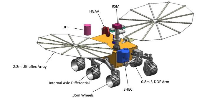
1. Scientific Objectives
Science Questions and Objectives
The Mars Astrobiology Explorer-Cacher (MAX-C) mission, a proposed rover to be launched in 2018,
would have the dual objectives of conducting high-priority in situ science and obtaining rock samples for
eventual return to Earth.
The current emphasis of the Mars Exploration Program is to answer the question “Did life ever arise on
Mars?” Exploration for life on Mars requires a broad understanding of integrated planetary processes in
order to identify those locations where habitable conditions are most likely to exist today or to have
existed in the past and where conditions are or were favorable for preservation of any evidence of life.
Therefore, this endeavor must also investigate the geological and geophysical evolution of Mars; the
history of its volatiles and climate; the nature of the surface and subsurface environments, now and in the
past; the temporal and geographic distribution of liquid water; and the availability of other resources (e.g.,
energy) necessary for life.
Accordingly, assessing the full astrobiological potential of martian environments requires much more than
identifying locations where liquid water was present. It is also necessary to characterize more
comprehensively the macroscopic and microscopic fabric of sediments and other materials, identify any
organic molecules, reconstruct the history of mineral formation as an indicator of preservation potential
and geochemical environments, and determine specific mineral compositions as indicators of coupled
redox reactions characteristic of life. The requirement for such information guides the selection, caching,
and return of relevant samples in order to address the life question effectively in sophisticated
laboratories on Earth.
The acquisition and return to Earth of martian materials has been a high science priority since the 1970s.
The proposed MAX-C would start the sequence of missions to enable Mars sample return to be
accomplished in a way that effectively would address the search for evidence of life.
To ensure access to the scientifically most valuable samples, MAX-C would be designed to rove 20 km
over a 500-sol nominal lifetime. It would feature mast-based remote sensing instrumentation, arm-based
in situ measurement capability, and the ability to obtain rock cores for a primary and contingency pair of
sample caches. These caches would be retrieved during a subsequent mission by a fetch rover for return
to a Mars ascent vehicle for eventual return to Earth.
Prioritized Science Objectives
The proposed scientific objectives for this mission are as follows:
At a site interpreted to represent high habitability potential, and with high preservation potential
for physical and chemical biosignatures:
evaluate paleoenvironmental conditions,
characterize the potential for the preservation of biotic or prebiotic signatures, and
access multiple sequences of geological units in a search for possible evidence of ancient life
and/or prebiotic chemistry.
Collect, document, and package (in a manner suitable for potential return to Earth) the samples
necessary to achieve the proposed scientific objectives of the potential future sample return
mission.
Table 1-1 describes the linkages between the proposed science objectives and how they would be
achieved. Note that functional requirements are requirements placed by science on the mission concept
(e.g., requirements on the spacecraft, trajectory, mission architecture, etc.).
Mars 2018 MAX-C Caching Rover 1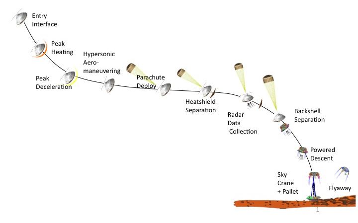
Driving Requirements
In addition to the scientific objectives, MAX-C would have a number of driving requirements based on
programmatic and engineering considerations. These proposed requirements are as follows:
Land on terrain with elevations relative to the Mars Orbiter Laser Altimeter (MOLA)–defined
areoid of up to −1 km and within a latitude belt between 15°S and 25°N with a 3-sigma landing
error ellipse of 11 km.
Drive 20 km to access important geological materials for imaging and spectral characterization
using remote sensing instrumentation, followed by contact-based elemental, mineralogical, and
textural measurements of natural rock surfaces and interior surfaces exposed by brushing and
grinding.
Acquire 19 primary and 19 contingency rock cores, each 10 g in mass, for rock targets shown by
MAX-C remote sensing and contact measurements to provide a high likelihood of preserving
evidence for past environmental conditions, habitability, and perhaps life. Place these cores in
primary and contingency caches for retrieval by a subsequent mission and fetch rover. Two
caches would be needed to maximize the probability of getting samples back to Earth (e.g., if first
cache is lost due to ascent vehicle failure or if the MAX-C roves to an area that could not be
accessed by the fetch rover.)
Mars 2018 MAX-C Caching Rover 2Science Traceability
Table 1-1. Science Traceability Matrix
Science Objective Measurement Instrument Functional Requirement
Cache system Acquire, package, and preserve Dual cache system with two Acquire rock cores, encapsulate,
Acquire, package, and preserve a rock core sample carousels and deliver to a caching system
rock core sample cache for return Contain 19 primary rock cores
to Earth that has a high likelihood Deliver samples to the cache
of containing information needed without contaminating other
to reconstruct past environmental samples in the cache, or
conditions and information about damaging or degrading other
habitability and life capabilities
Validate that samples have been
delivered to the caching system
Each rock core mass to be 10 g
Ability to dispose of three
samples and change-out for three
new samples
Ability to release and store
contingency cache
Avoid excess heating, monitor
pressure and temperature
Survive intact on surface for at
least 10 years
Ability to collect sample of near- Collect rock sample Coring tool on arm Must be able to core into rocks
surface rock with variable hardness and grain
size distribution
Have sufficiently low dust and
vibration levels to not damage or
degrade other capabilities
Have ability to change worn-out
bits
Samples must not become
mixed/contaminated
Mars 2018 MAX-C Caching Rover 3Science Objective Measurement Instrument Functional Requirement
Must retain pristine nature of Encapsulate sample Encapsulation sleeves associated Avoid excess heating
samples prior to arrival on Earth with coring tool Need ability to relate specific core
samples to acquisition time and
location, e.g., by labelling cores
Ability to link sample to field Wide-angle stereo. High Pancam + Vis-NIR filtering on Spectral filter sets 400 nm–1 mm,
context resolution. rover mast— in a position that at least 12 filters
Identify and select samples that allows the imager to observe the Sensitivity at least as good as
are different from each other by maximum area around the rover Mars Exploration Rover (MER)
imaging (in visible light) the Angular resolution at least as
morphology of naturally occurring good as Pancam on MER
and disturbed (by MAX-C)
landforms, soils, and rocks
Capable of determining the Texture and microscopic imaging Microscopic Vis-IR imager in a Spectral resolution, spatial
texture of rocks and soils in situ. position that allows the imager to resolution, and sensitivity at least
Ability to image the surface on the observe the maximum area as good as MER
scale of 100s of microns prior to, around the rover
during, and after coring
operations
Spatially resolved mineralogical Mineralogy and organic detection Raman point or mapping Green and deep UV Raman
and organic compound detection spectroscopy on the arm. Needs Beam size of2. High-Level Mission Concept Overview The proposed Mars 2018 MAX-C caching rover mission would launch NASA’s MAX-C and ESA’s ExoMars rovers and land them together on a pallet using the “Sky Crane” concept developed for MSL. The strawman instrument set includes a panoramic camera, a near-infrared (NIR) spectrometer, a microscopic imager, an Alpha Particle X-Ray Spectrometer (APXS), and a dual wavelength Raman spectrometer. These instruments would locate, study, and select samples for possible return to Earth. These samples would be acquired and encapsulated by MAX-C’s sampling handling system and deposited in a cache or a backup cache. The caches would be placed on the surface of Mars to await retrieval by a fetch rover from the proposed future Mars Sample Return mission. The proposed MAX-C rover 2018 mission would be launched in May 2018 on a NASA-supplied Atlas V 531–class launch vehicle on a Type I trajectory and would arrive approximately 8 months later in January 2019, at the tail end of the martian dust storm season. The rovers would land in a region of Mars between latitudes 25°N and 15°S. The rovers would be enclosed in an aeroshell inside the cruise stage for the duration of cruise. Prior to atmospheric entry, the entry system would be released from the cruise stage. The entry system would consist of the aeroshell, which would protect the pallet and rovers during cruise and entry, and a supersonic parachute (and deployment system) to slow the entry vehicle until the Sky Crane, pallet, and rovers could be released from the aeroshell. The entry system would separate the aeroshell system from the cruise stage, deploy the parachute, release the heat shield, and then separate the descent stage from the entry system. The descent stage would employ a platform above the pallet and rovers to provide a powered descent and a Sky Crane to lower the pallet and rovers onto the surface of Mars. After the pallet has touched down, the descent stage would cut the bridle and umbilical cables to free itself from the pallet and then fly away from the rover’s touchdown site. Once the pallet has been deployed onto the martian surface, bipods could be articulated in order to level the platform and provide a more controlled egress path from the top deck. Egress would be accomplished utilizing inflated textile egress ramps deployed over the deployed bipods, thereby providing a safe and controlled path in any direction from the top deck of the landing pallet. After egress, the two rovers would go through a checkout period and then begin science operations. The proposed MAX-C rover would be expected to collect a total of 38 samples, 19 in each of two sample caches. The mission would be required to last 500 sols (514 Earth days) and traverse at least 20 km. Concept Maturity Level MAX-C design requirements requested by the Planetary Science Decadal Survey Mars Panel were reviewed against the Jet Propulsion Laboratory’s (JPL’s) concept maturity level (CML) guidelines (Table 2-1). JPL reviewers determined that MAX-C is at CML 4. Two NASA Science Advisory groups reviewed the proposed science objectives and traceability, and a joint NASA-ESA Science Advisory Group is studying joint operations of the two rovers. NASA and ESA have defined and agreed upon their respective responsibilities. The ExoMars rover is in an advanced state of development and the instruments have been selected. The proposed MAX-C rover and the remaining flight elements are in preliminary design at the pre-Phase A level. Mars 2018 MAX-C Caching Rover 5
Table 2-1. Concept Maturity Level Definitions
Concept
Maturity Level Definition Attributes
CML 6 Final Implementation Requirements trace and schedule to subsystem level,
Concept grassroots cost, V&V approach for key areas
CML 5 Initial Implementation Detailed science traceability, defined relationships and
Concept dependencies: partnering, heritage, technology, key
risks and mitigations, system make/buy
CML 4 Preferred Design Point Point design to subsystem level mass, power,
performance, cost, risk
CML 3 Trade Space Architectures and objectives trade space evaluated for
cost, risk, performance
CML 2 Initial Feasibility Physics works, ballpark mass and cost
CML 1 Cocktail Napkin Defined objectives and approaches, basic architecture
concept
Technology Maturity
This mission concept would require the development of several capabilities prior to the mission
preliminary design review (PDR). The technology challenges are described below.
Sample Acquisition and Encapsulation
NASA has limited experience in planetary sample acquisition. On Mars, the experience is limited to Viking
and Phoenix scoops for sampling regolith. The proposed MAX-C rover would acquire rock cores
(~20 cores, ~1 cm ~5 cm). The core samples would have to be collected in sample tubes, sealed, and
registered to the specific locations on the surface of Mars. Rock core sampling is the key challenge.
Currently, no flight heritage system is available to perform this function. There is, however, a considerable
technology development history in this area. In addition to many prototyping efforts in the past, two coring
tools were developed by Honeybee Robotics for Mars applications (Mini-Corer and Corer-Abrader Tool,
or CAT) that were flight prototypes. Current maturity for the system as a whole (i.e., coring tool, sample
handling) and controls is technology readiness level (TRL) 3.
Terrain-Relative Descent Navigation and Precision Landing
Since the proposed MAX-C and ExoMars rovers would land together on a pallet rather than on rocker-
bogie wheels, a capability is needed to ensure safe landing through the avoidance of rocks and slopes.
This technology could be used to guide the lander to perform a lateral divert maneuver to a safe landing
location, just prior to touchdown. This technology is currently TRL 3–4.
Mobility
Increasing the Average Rover Speed
The average rover speed could be increased by reducing the time that is required to compute the “sense”
and “think” portion of a move cycle. Currently, each half-a-meter move cycle takes as long as 350 s for a
20-s move. The approach would be to speed up the computations using co-processors. This technology
is TRL 4.
Reducing Control Electronics Volume and Mass
The volume and mass of the motor control electronics could be reduced by using a decentralized motor
controller architecture. This would require the development of credit card–size controllers that would be
co-located with the motors and operate in the Mars ambient temperatures. This technology is TRL 5.
Mars 2018 MAX-C Caching Rover 6Round-Trip Planetary Protection
The proposed 2018 MAX-C/ExoMars mission is expected to be categorized as Class IVa overall and
Class IVb for the sampling system. See Section 3 for a discussion of the proposed 2018 MAX-C round-
trip planetary protection.
Instruments
Three of the instruments (Pancam, Microscopic Imager [MI], and APXS) have previously flown on
missions and are TRL 9.
The current fluorescence/Raman band instrument concept is TRL 5. The current version of the instrument
has been tested in the Antarctic, the Arctic, the Mojave Desert, and Svalbard (Norway) with funding by
NASA Astrobiology Science and Technology Instrument Development, NASA Astrobiology Science and
Technology for Exploring Planets, U.S. Army, and U.S. Defense Threat Reduction Agency. No flight
heritage exists for this instrument. The modifications currently being made are associated with
miniaturization of the spectrometer and laser source.
The NIR spectrometer concept is based on a simplified version of the concept Mini-M3, a modified design
of a previous instrument (Moon Mineralogy Mapper [M3]), and, as such, claims moderate heritage. All
major NIR spectrometer components have flown in space on previous missions are flight qualified.
Instrument modifications are primarily packaging, thermal design, and simplification of the electronics.
Mini-M3 is TRL 6.
Because these instruments would be selected under a competitive announcement, the technology
development for these instruments is not included as part of the 2018 technology development program.
Key Trades
The MAX-C team has already addressed a number of key trades, some of which strongly benefited from
the MSL extensive review and similar trades during its design. Many of these trades focus on the landing
system. For both MSL and the proposed 2018 mission, extensive reviews of the airbag architecture (Mars
Pathfinder, MER) versus the Sky Crane architecture (MSL) versus the legged lander (Viking, Phoenix)
have been conducted. In addition, the capability of landing on a pallet versus landing on wheels has been
newly explored for 2018. In order to accommodate the two rovers, the team also reviewed the
implications of staying with an aeroshell size of 4.5 m or increasing the aeroshell to a diameter of 4.7 m.
The team also studied the shape of the aeroshell, using either the Apollo aeroshell or the Viking aeroshell
(which is used on MSL) and concluded that the Viking aeroshell at 4.7 m provided adequate margin for
accommodating all the flight elements.
Several key trade studies remain to be conducted. These include the following:
Landing platform and egress aids to accommodate MSL-like hazards
A study will assess the trades between platform capabilities and hazard reduction through base-
lined terrain-relative navigation rock hazard detection and avoidance, and/or landing site
restrictions.
Volume available in aeroshell
Options for a more volumetrically efficient heat shield shape need to be explored while the team
also studies the options to reduce rover size (e.g., modest mobility reductions, optimized internal
layout, aspect ratio trades).
Mars 2018 MAX-C Caching Rover 73. Technical Overview
Strawman Instrument Payload Description
The MAX-C strawman payload consists of a complementary set of five optical and spectrometry
instruments that would be used to select and analyze samples to understand past environmental
conditions and the probability of conditions for habitability. The most interesting samples would be stored
in primary and backup sample caches that would potentially be returned at a later date by the proposed
Mars Sample Return mission. The payload represents a mix of already-flown instruments (Pancam,
APXS, and MI, all TRL 9) and newer proven technologies (NIR point spectrometer, Raman spectrometer,
both TRL 5). A summary of payload mass and power (Table 3-11) follows the instrument discussions
below.
Pancam
The Pancam (Table 3-1) is a high-resolution stereo imager that has flown previously on both MERs and
the Phoenix lander. Images from Pancam would be used to identify potential sampling sites in the field
and evaluate them in the context of their surroundings. Pancam would be used in studies of morphology,
topography, and geology, as well as in studies of atmospheric dust and opacity. Pancam consists of two
digital cameras, each with a 1024 1024 active imaging area from transfer charge-coupled device (CCD)
detector array. Each camera includes a small eight-position filter wheel to allow multispectral studies in
the 400–1100 nm wavelength range. The optics has an effective focal length of 43 mm and a focal ratio of
f/20, for an instantaneous field of view (FOV) of 0.27 mrad/pixel and a FOV of 16° 16°. Pancam would
be used to generate panoramas of the landing site area and other important sites. Imaging of the martian
sky would be done on a periodic basis, together with imaging of the sun through the solar filters to
determine aerosol properties. Calibration would be performed through a variety of means: a brief
calibration campaign at the beginning of the mission, imaging of the sky and sun, downlinking reference
pixel and dark current images, and imaging of the calibration target.
Table 3-1.Pancam (Mast)
Item Value Units
Panorama camera 2
Number of channels 2
Size/dimensions 50 60 110 cm cm cm
Instrument mass without contingency (CBE*)/ per unit 1.2 kg
Instrument mass contingency 30 %
Instrument mass with contingency (CBE+Reserve) 1.6 kg
Instrument average payload power without contingency (80% 2.4 W
during mast science) / per unit
Instrument average payload power contingency 30 %
Instrument average payload power with contingency 3.1 W
Instrument average science data rate^ without contingency 8000 kbps
Instrument FOVs (if applicable) 16.8 16.8 degrees
Pointing requirements (knowledge) 0.1 degrees
Pointing requirements (control) 2 degrees
**CBE = Current best estimate
^Instrument data rate defined as science data rate prior to on-board processing
Mars 2018 MAX-C Caching Rover 8NIR Spectrometer
The NIR spectrometer (Table 3-2) is a passive instrument that operates in the visible and short-wave
infrared (SWIR) portion of the spectrum to provide detailed mineral maps of the surrounding terrain and
the mineral composition of specific rocks and outcrops. Spatial resolution varies with distance from the
target, reaching down to a few millimeters at distances below 10 m. Its spectral range and spectral
resolution are similar to those of the orbiting Compact Reconnaissance Imaging Spectrometer for Mars
(CRISM) and Observatoire pour la Minéralogie, l’Eau, les Glaces et l’Activité (OMEGA) instruments,
allowing extension of the orbital measurements to higher spatial resolution in addition to providing
“ground truth” data. The NIR spectrometer has no mechanisms other than the scanning in x and y
provided by the mast. Each pixel is simultaneously imaged in ~420 spectral bands over a range of 400–
2200 nm where the spectral resolution is 5 nm.
Table 3-2. NIR Point Spectrometer (Mast)
Item Value Units
Number of channels 1
Size/dimensions 2000 90 200 mm mm mm
Instrument mass without contingency (CBE*)/ per unit 3.5 kg
Instrument mass contingency 30 %
Instrument mass with contingency (CBE+Reserve) 4.6 kg
Instrument average payload power without contingency (80% 9.6 W
during mast science)
Instrument average payload power contingency 30 %
Instrument average payload power with contingency 12.5 W
Instrument average science data rate^ without contingency 8000 kbps
Pointing requirements (knowledge) 0.1 degrees
*CBE = Current best estimate
^Instrument data rate defined as science data rate prior to on-board processing
Microscopic Imager
The MI (Table 3-3) is a high-resolution imager that would be mounted on the turret on the proposed MAX-
C arm. MI has previously flown on MER. The MI would be used to image the fine-scale morphology,
texture, and reflectance of surfaces and to identify areas for further study by other turret instruments as
well as areas for sampling. The MI uses a camera body identical to that of Pancam and has the same
radiometric performance as Pancam. The MI has a focal length of 20 mm and a working distance of 63
mm from the front of the lens barrel to the object plane. MI’s spectral range is 400–680 nm. The MI has a
transparent dust cover that remains closed except during operations, and the instrument uses a contact
sensor to ensure correct positioning and prevent accidental damage. MI would be used in conjunction
with the Raman and APXS to select the desired area for sampling; therefore, the MI must be able to
accurately image the same areas as the Raman.
Mars 2018 MAX-C Caching Rover 9Table 3-3. Microscopic Imager (Arm) MI Design
Item Value Units
Number of channels 1
Size/dimensions 80 80 100 mm mm mm
Instrument mass without contingency (CBE*)/ per unit 0.3 kg
Instrument mass contingency 30 %
Instrument mass with contingency (CBE+Reserve) 0.4 kg
Instrument average payload power without contingency (3% 0.3 W
during arm science)
Instrument average payload power contingency 30 %
Instrument average payload power with contingency 0.4 W
Instrument average science data rate^ without contingency 8000 kbps
Instrument FOVs (if applicable) 31 31 mm
*CBE = Current best estimate
^Instrument data rate defined as science data rate prior to on-board processing
Alpha-Particle X-Ray Spectrometer (APXS)
The Alpha-Particle X-Ray Spectrometer (APXS, Table 3-4) is a contact instrument that uses X-ray
spectroscopy to determine the elemental composition of soils and rocks with a focus on iron-bearing
minerals. Radioactive sources contained within the APXS sensor head irradiate the sample material,
resulting in X-ray emissions that are characteristic signatures of the chemical elements within the
material. An energy dispersive X-ray detector provides x-ray spectra from 700 eV to ~25 keV with energy
resolution of ~150 eV at Fe K, covering elements from atomic number Z=11 to 35 and beyond.
Measurement spot size in contact is approximately 1.5 cm. Operation of the APXS would require the
preparation of the surface to be observed by a RAT-like tool in the sampling system and placement of the
APXS on the target for a specific length of time dependent on the target. The APXS on MAX-C would be
identical to the unit being flown on MSL, and derives heritage from the APXS on MER. APXS consists of
a sensor head on the turret, electronics in the rover chassis, and a calibration target mounted on the rover
chassis.
Table 3-4. APXS (Arm)
Item Value Units
Number of channels 1
Size/dimensions 105 60 90 mm mm mm
Instrument mass without contingency (CBE*)/ per unit 1.7 kg
Instrument mass contingency 30 %
Instrument mass with contingency (CBE+Reserve) 2.2 kg
Instrument average payload power without contingency (42% 5.6 W
during arm science)
Instrument average payload power contingency 30 %
Instrument average payload power with contingency 7.3 W
Instrument average science data rate^ without contingency 18 kbps
Instrument FOVs (if applicable) 15 mm
*CBE = Current best estimate
^Instrument data rate defined as science data rate prior to on-board processing
Mars 2018 MAX-C Caching Rover 10Dual Wavelength Raman/Fluorescence Instrument The Raman/fluorescence instrument (Table 3-5) is an arm-mounted system for detection and characterization of organics in martian rocks. As a first-order capability, the dual-wavelength Raman/fluorescence instrument would enable micro-mineralogy coupled to sub-parts-per-billion in situ detection of organics to identify samples for high-priority caching interest. However, to avoid possible loss of detected organics during caching or as a result of caching, the instrument would enable the equally important in situ mapping and characterization of organics with spatially correlated mineralogical context and could lead to a clear understanding of whether the organics are a result of endogenous or exogenous processes (planetary processes or meteoritic/astroidal/cometary impacts). In addition to organics and mineral analysis, the dual-wavelength Raman/fluorescence instrument would detect and map variations in water content with detection limits down to monolayers. By coupling to imaging data from the NIR spectrometer and MI investigations of minerals and textures, a comprehensive characterization of minerals at a variety of spatial scales becomes possible, providing a clear perspective on the formation and subsequent alteration of these minerals. These investigations avoid sample handling and would require minimally processed surfaces (abrading) in a manner that preserves the spatial information. The dual-wavelength Raman/fluorescence instrument is an active device that utilizes a deep ultraviolet (UV) laser source at 248 nm to simultaneously obtain Raman and native fluorescence signals from organics on the sample and a visible 532 nm laser for characterization of minerals by Raman spectroscopy. The complete instrument consists of an arm-based detection head with electronics located in the rover body. The instrument operates from distance of ~50 mm and has a 1 mm depth of focus. Hyperspectral spatial maps for both the organics and minerals are acquired over 1 cm2 by rastering a
Sampling System
The Sampling System (Tables 3-6 through 3-11) would consist of a five degree-of-freedom manipulator
arm to deploy and align the instruments and the rotary percussive coring tool (drill) as well as to provide
alignment, feed, and preload for the tool. The tool would provide coring, core break-off, core retention and
bit capture and release for bit change-out. The caching subsystem concept is referred to as the Sample
Handling, Encapsulation, and Containerization (SHEC) subsystem (Figure 3-1). Bit change-out and
sample caching are combined in the design. There is one opening in the SHEC subsystem, the port for
transferring a coring bit. There are four actuators, one for combined bit carousel and sample carousel
rotation, one for transfer arm rotation, one for transfer arm linear motion, and a solenoid to activate the
transfer arm gripper. Multiple bits would be available for coring of various rock types, and a RAT-like
function would be included in the form of an abrader bit. Sample tubes would be inserted into the bits
prior to sample collection, and the sample-filled tubes would be removed from the bits post acquisition
and stored in the sample canister. The sample canister would then be removed from the SHEC by the
manipulator arm and left for retrieval by the proposed future Mars Sample Return mission.
Table 3-6. Cache Sample Handling, and Container
Item Value Units
Number of channels 1
Size/dimensions 400 340 340 mm mm mm
Instrument mass without contingency (CBE*)/ per unit 9.0 kg
Instrument mass contingency 30 %
Instrument mass with contingency (CBE+Reserve) 11.7 kg
Instrument average payload power without contingency (64% 6.4 W
during sample tool manipulation)
Instrument average payload power contingency 30 %
Instrument average payload power with contingency 8.3 W
Instrument average science data rate^ without contingency 1 kbps
*CBE = Current best estimate
^Instrument data rate defined as science data rate prior to on-board processing
Table 3-7. Corer/Abrader
Item Value Units
Number of channels 1
Size/dimensions 150 150 314 Mm mm mm
Instrument mass without contingency (CBE*)/ per unit 5.0 kg
Instrument mass contingency 30 %
Instrument mass with contingency (CBE+Reserve) 6.5 kg
Instrument average payload power without contingency (100% 75 W
during coring)
Instrument average payload power contingency 30 %
Instrument average payload power with contingency 97.5 W
Instrument average science data rate^ without contingency 1 kbps
*CBE = Current best estimate
^Instrument data rate defined as science data rate prior to on-board processing
Mars 2018 MAX-C Caching Rover 12Table 3-8. Mast
Item Value Units
Number of channels 1
Size/dimensions 0.7 m length mm
100 mm
diameter
Instrument mass without contingency (CBE*)/ per unit 7.7 kg
Instrument mass contingency 30 %
Instrument mass with contingency (CBE+Reserve) 10.0 kg
Instrument average payload power without contingency (10% 0.8 W
during Mast science)
Instrument average payload power contingency 30 %
Instrument average payload power with contingency 1.0 W
Instrument average science data rate^ without contingency 0 kbps
*CBE = Current best estimate
^Instrument data rate defined as science data rate prior to on-board processing
Table 3-9. Arm (Short, Low Pre-Load)
Item Value Units
Number of channels 1
Size/dimensions 0.8 m
Instrument mass without contingency (CBE*)/ per unit 10.3 kg
Instrument mass contingency 30 %
Instrument mass with contingency (CBE+Reserve) 13.4 kg
Instrument average payload power without contingency (36% 7.2 W
during sample tool manipulation)
Instrument average payload power contingency 30 %
Instrument average payload power with contingency 9.4 W
Instrument average science data rate^ without contingency 1 kbps
*CBE = Current best estimate
^Instrument data rate defined as science data rate prior to on-board processing
Table 3-10. Organic Blank
Item Value Units
Number of channels 1
Instrument mass without contingency (CBE*)/ per unit 1.5 kg
Instrument mass contingency 30 %
Instrument mass with contingency (CBE+Reserve) 2.0 kg
Instrument average payload power without contingency (100% 2 W
during coring)
Instrument average payload power contingency 30 %
Instrument average payload power with contingency 2.6 W
Instrument average science data rate^ without contingency 0 kbps
*CBE = Current best estimate
^Instrument data rate defined as science data rate prior to on-board processing
Mars 2018 MAX-C Caching Rover 13Table 3-11. Proposed Payload Mass and Power
Mass Op. Power Average Power
Payload Element CBE % MEV CBE % MEV CBE % Cont. MEV
(kg) Cont. (kg) (W) Cont. (W) (W) (W)
Pancam (mast, 1.2 30% 1.6 3 30% 4 1.0 30% 1.3
Phoenix, MER)
NIR point 3.5 30% 4.6 12 30% 16 4.0 30% 5.2
spectrometer (mast)
Raman spectrometer 5 30% 6.5 25 30% 33 8.3 30% 10.8
(body)
APXS (mast, MSL) 1.7 30% 2.2 10 30% 13 3.3 30% 4.3
MI (arm) MI design 0.3 30% 0.4 10 30% 13 3.3 30% 4.3
Mast 7.7 30% 10.0 8 30% 10 2.7 30% 3.5
Cache sample 9 30% 11.7 10 30% 13 3.3 30% 4.3
handling and
container
Arm => short, low 10.3 30% 13.4 20 30% 26 6.7 30% 8.7
pre-load
Organic blank 1.5 30% 2.0 2 30% 3 0.7 30% 0.9
Corer/abrader 5 30% 6.5 75 30% 98 25.0 30% 32.5
Total proposed 45.2 – 58.9 175 – 229 58.3 – 75.8
payload mass
Figure 3-1. The Proposed MAX-C SHEC Subsystem.
Single cache is shown; baseline approach is dual-cache system.
Mars 2018 MAX-C Caching Rover 14Flight System The flight system for the proposed 2018 MAX-C mission would include 6 flight elements: the MAX-C rover, the ExoMars rover, the landing pallet, the descent stage, the entry system, and the cruise stage. The MAX-C rover is a new design. The ExoMars rover is the ESA rover under development previously for the 2016 ExoMars mission. The landing pallet would carry the two rovers. The descent stage, the entry system, and the cruise stage designs are derived from the MSL entry system. The current design of each element is described in more detail below. MAX-C Rover The proposed MAX-C rover (Figure 3-2 and Tables 3-12 and 3-13) is envisioned as a MER-class rover, upsized to accommodate the need to collect and cache samples. The rover would be solar powered, the mobility system would accommodate 35 cm hazards, and there would be mast- and arm-mounted instrumentation. Upgrades include the ability to collect and cache samples for potential later return to Earth. The proposed MAX-C rover would be powered by two Ultraflex solar arrays. MAX-C would be approximately 50% larger than size of the MER rover and travels on a wheelbase of approximately 1.7 m by 1.6 m providing a ground clearance of approximately 0.35 m. The rover chassis design is 1.1 m in length, 0.75 m wide, and 0.46 m tall and would support a forward mounted robotic arm supporting a dual Raman spectrometer head, an APXS head, and an MI head. A dual-canister SHEC would also be installed on the forward panel. Attached to the top deck of the chassis, an instrument mast would be used to mount a Pancam and NIR spot/line spectrometer head. The total mass of the flight elements would be approximately 3848 kg, of which 365 kg is the MAX-C rover (including 43% margin). The total launch wet mass is estimated to be 4450 kg, which would fit on an Atlas V 531 class launch vehicle using a 2018 Type I trajectory The rover would be delivered to the surface of Mars aboard the pallet, which would be lowered by the entry and descent stages. The rover would have a single inertial measurement unit (IMU) that would be used for 3-axis attitude measurement during deployment. Forty-two distributed drive controllers and actuators would be used to perform various functions of the rover including speed and high-gain antenna (HGA) gimbal control. Four hazard cameras and two navigation cameras are provided but generally only two would be used at a time to save power. The avionics would use the standard JPL internal approach: RAD750, critical relay control card, non- volatile memory and camera card, telecom interface card, serial interface assembly, remote engineering units, and power converters. The data storage of 4Gbits (on the NVMCAM) should be able to support the science mission with ample margin. A maximum data collection rate of 3.04 kbps (or 270 Mbits/sol) was assumed. The proposed MAX-C rover would contain new avionics development for the distributed motor controller system. The rover would employ selected redundancy on key components to address fault tolerance. The rover would have two Ultraflex solar arrays at a total area of 6.03 m2. The battery would use small cell Li-Ion technology in a single 30 A-Hr module. The mission would require approximately 1600 W- hrs/sol during surface operations. The MAX-C rover would utilize MSAP architecture for the electronics, which has MSL heritage. The proposed MAX-C rover thermal design would benefit from extensive heritage from Pathfinder, MER and MSL. The rover must be able to withstand temperatures from -40C to +50C. The warm electronics box (WEB) and the instrument complement would be smaller than on MSL. The WEB and the battery assembly would employ MSL-heritage CO2 insulation. Radioisotope heater units (RHUs) would be employed as they were in MER, with additional electrical heaters for warm-up and remote locations. Mars 2018 MAX-C Caching Rover 15
Figure 3-2. The Proposed MAX-C Rover
MAX-C would support a two-way link with Earth through all phases of the mission, consisting of direct-to-
Earth (DTE) communications via X-band and at ultra-high frequency (UHF) via a relay orbiter. The
telecommunications system has high heritage from MSL except that the UHF subsystem would be single
string. The system would employ one 2-axis gimbaled 0.28m HGA for primary communications and one
X-band low-gain antenna (LGA) as required. The system would use one small deep space transponder
(SDST) for X-band communications and one UHF Electra Lite. It is expected that the relay assets would
provide two passes of at least 5 minutes each sol. The use of Ka band for telecommunications from the
surface of Mars is not currently feasible.
A top-level mass and power summary for the proposed MAX-C rover is shown in Table 3-12. The mass
contingency policy is based on the subsystem- and system-level contingency factors. Each subsystem
designer provides a contingency factor based on the degree of subsystem heritage and complexity. Once
the dry mass is summed up, the total subsystem contingency is computed. A systems contingency factor
is additionally applied to ensure that the total contingency is 43% (i.e., total subsystem contingency +
system contingency = 43%). The 43% system contingency factor is based on the JPL design principles.
The power contingency policy is to add 43% contingency to the total power for each power mode.

            Table 3-12. MAX-C Mass/Power Preliminary Estimates
                                                        Mass                        Average Power
                                             CBE                       MEV      CBE       %     MEV
            Flight Element                    (kg)        % Cont.       (kg)    (W)     Cont.   (W)
 Structures and mechanisms                   94.5          30%         122.8      0      43%      0
 Thermal control                             16.9          19%         20.2       3      43%      4
 Propulsion (dry mass)                          0           0%            0      0       43%      0
 Attitude control                              7.5         22%           9.1     10      43%      14
 Command and data handling                   12.5           7%         13.4      53      43%     76
 Telecommunications                           15.1          7%         16.2      13      43%     19
 Power                                        41.9         30%         54.5      27      43%     39
 Total flight element dry bus mass           254.9         43%          365

Mars 2018 MAX-C Caching Rover                                                                          16
Table 3-13. Proposed MAX-C Rover Characteristics
Flight System Element Parameters (as appropriate) Value/Summary, units
General
Design life, months 500 sol
Structure
Structures material (aluminum, exotic, composite, etc.) Aluminum/titanium/composites
Number of articulated structures 1 (2-axis gimbaled HGA)
Number of deployed structures 2 (Ultraflex arrays and mast)
Aeroshell diameter, m N/A
Thermal Control
Type of thermal control used Active (e.g., electric heaters,
temperature sensors) and
passive elements (e.g.,
proposed RHUs, MLI)
Propulsion
Estimated delta-V budget, m/s N/A
Propulsion type(s) and associated propellant(s)/oxidizer(s) N/A
Number of thrusters and tanks N/A
Specific impulse of each propulsion mode, seconds N/A
Attitude Control
Control method (3-axis, spinner, grav-gradient, etc.). 3-axis
Control reference (solar, inertial, Earth-nadir, Earth-limb, etc.) Inertial
Attitude control capability, degrees < 2 degrees
Attitude knowledge limit, degrees 1 degree
Agility requirements (maneuvers, scanning, etc.) Able to traverse 20 km
Articulation/#–axes (solar arrays, antennas, gimbals, etc.) 1 articulation / 2 axes (HGA)
Sensor and actuator information (precision/errors, torque, N/A
momentum storage capabilities, etc.)
Command & Data Handling
Flight element housekeeping data rate, kbps 2 kbits/s
Data storage capacity, Mbits 4000 Mbits
Maximum storage record rate, kbps 270 Mbits/sol (3 kbps)
Maximum storage playback rate, kbps 2 Mbps (UHF)
Power
Type of array structure (rigid, flexible, body mounted, deployed, Deployed Ultraflex
articulated)
Array size, meters meters 6.03
Solar cell type (Si, GaAs, multi-junction GaAs, concentrators) GaAs triple-junction Ultraflex
Expected power generation at Beginning of Life (BOL) and End of BOL = 677 W, EOL = 612 W
Life (EOL), watts
On-orbit average power consumption, watts ~70 W (peak = 270 W)
Battery type (NiCd, NiH, Li-ion) Li-ion
Battery storage capacity, amp-hours 30 A-hrs
Mars 2018 MAX-C Caching Rover 17ExoMars Rover
The ExoMars rover was carried as a mass allocation of 300 kg in this study. The pallet was designed to
accommodate the dimensions of both rovers, based on the current understanding of their designs.
Pallet
In an evolution of the Sky Crane delivery system, the capability of delivering a payload has been
increased from delivering an individual rover to providing a flexible platform capable of supporting multiple
payloads. A landing pallet (Tables 3-14 and 3-15) would interface with the descent stage at its outer
edges utilizing four bipods. By moving the interface points to the outer edges, the internal area provided
by the pallet would enable a variety of payloads to be delivered at any given time. In the current
configuration, adequate volume is provided for both the MAX-C rover as well as ExoMars. The pallet itself
would comprise a structural deck with a crushable material attached to its underside, providing rock strike
protection. As described above, once the pallet has been deployed onto the martian surface, the bipods
could be articulated in order to level the platform and provide a more controlled egress path from the top
deck. Egress would be accomplished utilizing inflated textile egress ramps deployed over the deployed
bipods, providing a safe and controlled path in any direction from the top deck of the landing pallet. The
landing platform would have commanded heater elements for the stand up actuator, and temperature
sensors for platform electronics and the actuator.
Table 3-14. Pallet Mass and Power Preliminary Estimates
Mass Average Power
Flight Element CBE MEV CBE % MEV
(kg) % Cont. (kg) (W) Cont. (W)
Structures and mechanisms 209.3 30% 272.1 0 43% 0
Cabling 11.3 30% 14.7 0 43% 0
Thermal control 0.7 6% 0.8 0 43% 0
Propulsion (dry mass) 0 0% 0 0 43% 0
Attitude control 0.6 10% 0.7 4 43% 6
Command and data handling 0 0% 0 0 43% 0
Telecommunications 0 0% 0 0 43% 0
Power 7.0 30% 9.1 4 43% 6
Total fight element dry bus mass 229 30% 297.4 – – –
Table 3-15. Proposed Pallet Characteristics
Flight System Element Parameters (as applicable) Value/Summary, units
General
Design life, months ~ Minutes (duration of EDL)
Structure
Structures material (aluminum, exotic, composite, etc.) Aluminum/titanium/composites
Number of articulated structures 1 (bipods)
Number of deployed structures 1 (egress ramp)
Aeroshell diameter, m N/A
Thermal Control
Type of thermal control used Active (e.g., electric heaters, temperature
sensors) and passive elements (e.g.,
proposed RHU, MLI)
Propulsion N/A
Attitude Control
Mars 2018 MAX-C Caching Rover 18Flight System Element Parameters (as applicable) Value/Summary, units
Control method (3-axis, spinner, grav-gradient, etc.). N/A
Control reference (solar, inertial, Earth-nadir, Earth- Inertial
limb, etc.)
Attitude control capability, degrees N/A
Attitude knowledge limit, degrees N/A
Agility requirements (maneuvers, scanning, etc.) ACS electronics able to level pallet and lift
the rover
Articulation/#–axes (solar arrays, antennas, gimbals, 0
etc.)
Sensor and actuator information (precision/errors, ACS electronics assume that commands for
torque, momentum storage capabilities, etc.) leveling the pallet and lifting the rover are
sent from Earth
Command & Data Handling N/A
Power
Type of array structure (rigid, flexible, body mounted, N/A
deployed, articulated)
Array size, meters meters N/A
Solar cell type (Si, GaAs, multi-junction GaAs, N/A
concentrators)
Expected power generation at BOL and EOL, watts BOL = 677 W, EOL = 612 W
On-orbit average power consumption, watts ~ 10W (peak = 13W)
Battery type (NiCd, NiH, Li-ion) Li-ion (Uses rover’s batteries)
Battery storage capacity, amp-hours 30 A-hrs (Uses rover’s batteries)
Descent Stage
The descent stage design (Tables 3-16 and 3-17) is based on the Sky Crane design used by MSL. The
descent stage would employ a platform above the pallet and rovers to provide a powered descent and a
Sky Crane to lower the pallet and rovers onto the surface of Mars. After the pallet has touched down, the
descent stage would cut the bridle and umbilicals to free itself from the pallet and fly away. On the
proposed 2018 mission, the mechanical/structural subsystems have been reconfigured to accommodate
the landing pallet and the two payloads onboard, but the remaining subsystems derive substantial
heritage from the original MSL design. Moving the interfaces to the outer edges of the descent stage
makes additional surface area available on the landing pallet, thereby allowing variation in the landed
payload as well as the simplified application to future missions.
The descent stage would handle all maneuvering and delta-V from cruise stage separation through
landing and flyaway. It would provide one additional propellant tank (for a total of four) and larger high-
pressure pressurant tanks. The system retains the heritage of the throttled MSL lander engines (MR-
80B), the pulse-mode reaction control system thrusters (MR-107U), and a space shuttle–spare
mechanical pressure regulator for pressure control. The propellant tanks would be ultralight composite
overwrapped with titanium liners.
The entry vehicle design is 3-axis controlled during entry, descent, and landing (EDL, Figure 3-3). Gyros
within the IMU would be used to propagate 3-axis attitude before and during aero-maneuvering. The IMU
and MSL-type descent sensor (for altitude) would be used to trigger parachuting and Sky Crane descent.
Descent motor electronics would trigger separation between the descent stage and rover. A “Multi-X”
hazard reduction system would be utilized for hazard avoidance. Once the drop package is landed,
leveling of the pallet and lifting of the rover would be conducted with an operator-in-the-loop.
Power systems on the descent stage derive their heritage from MSL. The descent stage uses three 9 A-
hr thermal batteries. Electronics are derived from the MSL descent stage. To support
Mars 2018 MAX-C Caching Rover 19You can also read