FALCON USER'S GUIDE - SpaceX
←
→
Page content transcription
If your browser does not render page correctly, please read the page content below
FALCON
 USER’S
 GUIDE
 JANUARY 2019

                                                        COPYRIGHT

Subject to the existing rights of third parties, Space Exploration Technologies Corp. (SpaceX) is the owner of the copyright
in this work, and no portion hereof is to be copied, reproduced, or disseminated without the prior written consent of
SpaceX.

                                   © Space Exploration Technologies Corp. All rights reserved.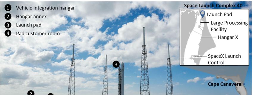
FALCON USER’S GUIDE

TABLE OF CONTENTS
1     INTRODUCTION .................................................................................................................... 1
    1.1       User’s Guide Purpose ......................................................................................................................................................... 1

    1.2       Company Description ......................................................................................................................................................... 1

    1.3       Falcon Program Overview ................................................................................................................................................. 1

              Falcon Launch Vehicle Safety .......................................................................................................................................... 2

    1.5       Falcon Reliability ................................................................................................................................................................. 3
      1.5.1           Engines ................................................................................................................................................................................................ 3

      1.5.2           Avionics................................................................................................................................................................................................ 4

      1.5.3           Staging Architecture and Design .................................................................................................................................................... 4

    1.6       Pricing ................................................................................................................................................................................... 4

2     VEHICLES .............................................................................................................................. 5
              Falcon 9 Vehicle Overview................................................................................................................................................. 5

              Falcon Heavy Vehicle Overview ....................................................................................................................................... 5

              Structure and Propulsion................................................................................................................................................... 6

              Retention, Release and Separation Systems ................................................................................................................ 8

              Avionics, and Guidance, Navigation and Control .......................................................................................................... 8

              Coordinate Frame ............................................................................................................................................................... 8

3     PERFORMANCE................................................................................................................. 10
              Available Injection Orbits .................................................................................................................................................10

              Mass-to-Orbit Capability ..................................................................................................................................................10

              Mass Properties ................................................................................................................................................................ 11

              Launch Windows ............................................................................................................................................................... 12

              Flight Attitude .................................................................................................................................................................... 12

              Separation Attitude and Accuracy ................................................................................................................................. 12

              Multiple Payloads .............................................................................................................................................................. 13

              Secondary Payloads ......................................................................................................................................................... 13

4     ENVIRONMENTS................................................................................................................ 14
              Transportation Environments......................................................................................................................................... 14

              Temperature, Humidity and Cleanliness ...................................................................................................................... 14

              Flight Environments ......................................................................................................................................................... 15
      4.3.1           Loads .................................................................................................................................................................................................. 15

      4.3.2           Sine Vibration .................................................................................................................................................................................... 17

      4.3.3           Acoustic ............................................................................................................................................................................................. 19

                                                      © Space Exploration Technologies Corp. All rights reserved.                                                                                                              ii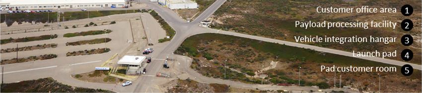
FALCON USER’S GUIDE

    4.3.4          Shock .................................................................................................................................................................................................. 25

    4.3.5          Random Vibration ............................................................................................................................................................................ 25

    4.3.6          Electromagnetic ............................................................................................................................................................................... 27

    4.3.7          Fairing Internal Pressure ................................................................................................................................................................ 34

    4.3.8          Payload Temperature Exposure during Flight............................................................................................................................ 34

    4.3.9          Free Molecular Heating .................................................................................................................................................................. 34

            Environmental Compatibility Verification ..................................................................................................................... 35

5   INTERFACES ......................................................................................................................36
            Mechanical Interfaces ...................................................................................................................................................... 36
    5.1.1          Payload Adapters and Separation Systems ............................................................................................................................... 36

    5.1.2          Payload Fairing ................................................................................................................................................................................. 36

            Electrical Interfaces .......................................................................................................................................................... 38
    5.2.1          Connectivity during Payload Processing and on Launch Pad ................................................................................................ 38

    5.2.2          Falcon-to-Payload Command Interface ...................................................................................................................................... 40

    5.2.3          Timing Services ................................................................................................................................................................................ 40

            Interface Compatibility Verification Requirements ....................................................................................................40

6   FACILITIES.......................................................................................................................... 41
            SpaceX East Coast Launch Facilities............................................................................................................................ 41
    6.1.1          Cape Canaveral Air Force Station, Florida .................................................................................................................................. 41

    6.1.2          Kennedy Space Center, Florida ..................................................................................................................................................... 41

    6.1.3          CCAFS & KSC Personnel Accommodations ............................................................................................................................... 42

            Vandenberg Air Force Base, California ......................................................................................................................... 44
    6.2.1          VAFB Personnel Accommodations .............................................................................................................................................. 45

            Headquarters—Hawthorne, CA ...................................................................................................................................... 47

            Rocket Development Facility—McGregor, TX.............................................................................................................. 47

            Government Outreach and Legal Affairs—Washington, DC ..................................................................................... 47

7   MISSION INTEGRATION AND SERVICES ................................................................... 48
            Contracting ......................................................................................................................................................................... 48

            Mission Management ...................................................................................................................................................... 48

            Standard Services ............................................................................................................................................................. 49

            Schedule .............................................................................................................................................................................50

            Customer Deliverables .....................................................................................................................................................50

8   OPERATIONS ...................................................................................................................... 52
            Overview and Schedule .................................................................................................................................................... 52

            Spacecraft Delivery and Transportation ....................................................................................................................... 52

                                                   © Space Exploration Technologies Corp. All rights reserved.                                                                                                             iii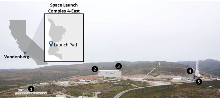
FALCON USER’S GUIDE

              Spacecraft Processing ..................................................................................................................................................... 53

              Joint Operations and Integration ................................................................................................................................... 55

              Launch Operations............................................................................................................................................................ 57
      8.5.1          Organization ...................................................................................................................................................................................... 57

      8.5.2          Spacecraft Control Center.............................................................................................................................................................. 57

      8.5.3          Launch Control ................................................................................................................................................................................. 58

      8.5.4          Rollout, Erection and Pad Operations .......................................................................................................................................... 58

      8.5.5          Countdown ........................................................................................................................................................................................ 59

      8.5.6          Recycle and Scrub ........................................................................................................................................................................... 59

              Flight Operations ............................................................................................................................................................... 59
      8.6.1          Liftoff and Ascent ............................................................................................................................................................................ 59

      8.6.2          Spacecraft Separation .................................................................................................................................................................... 59

      8.6.3          Contamination and Collision Avoidance ..................................................................................................................................... 59

      8.6.4          Post Launch Reports....................................................................................................................................................................... 59

      8.6.5          Disposal ............................................................................................................................................................................................. 59

              Sample Mission Profile ....................................................................................................................................................60

9     SAFETY ................................................................................................................................63
              Safety Requirements ........................................................................................................................................................ 63

              Hazardous Systems and Operations ............................................................................................................................ 63

              Waivers................................................................................................................................................................................ 63

10 CONTACT INFORMATION .............................................................................................. 64
11 QUICK REFERENCE ..........................................................................................................65
              List of Figures .................................................................................................................................................................... 65

              List of Tables...................................................................................................................................................................... 66

              List of Acronyms ............................................................................................................................................................... 66

              Change Log ........................................................................................................................................................................ 68

                                                     © Space Exploration Technologies Corp. All rights reserved.                                                                                                           iv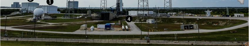
FALCON USER’S GUIDE

1 INTRODUCTION
1.1    USER’S GUIDE PURPOSE
The Falcon launch vehicle user’s guide is a planning document provided for customers of SpaceX (Space Exploration
Technologies Corp.). This document is applicable to the Falcon vehicle configurations with a 5.2 m (17-ft) diameter
fairing and the related launch service (Section 2).

This user’s guide is intended for pre-contract mission planning and for understanding SpaceX’s standard services. The
user’s guide is not intended for detailed design use. Data for detailed design purposes will be exchanged directly between
a SpaceX customer and a SpaceX mission manager.

SpaceX reserves the right to update this user’s guide as required. Future revisions are assumed to always be in process
as SpaceX gathers additional data and works to improve its launch vehicle design.

1.2    COMPANY DESCRIPTION
SpaceX offers a family of launch vehicles that improves launch reliability and increases access to space. The company
was founded on the philosophy that simplicity, reliability and cost effectiveness are closely connected. We approach all
elements of launch services with a focus on simplicity to both increase reliability and lower cost. The SpaceX corporate
structure is flat and business processes are lean, resulting in fast decision-making and product delivery. SpaceX
products are designed to require low-infrastructure facilities with little overhead, while vehicle design teams are co-
located with production and quality assurance staff to tighten the critical feedback loop. The result is highly reliable and
producible launch vehicles with quality embedded throughout the process.

Established in 2002 by Elon Musk, the founder of Tesla Motors, PayPal and the Zip2 Corporation, SpaceX has developed
and flown the Falcon 1 light-lift launch vehicle, the Falcon 9 medium-lift launch vehicle, the Falcon Heavy heavy-lift launch
vehicle, the most powerful operational rocket in the world by a factor of two, and Dragon, which is the first commercially
produced spacecraft to visit the International Space Station.

SpaceX has built a launch manifest that includes a broad array of commercial, government and international customers.
In 2008, NASA selected the SpaceX Falcon 9 launch vehicle and Dragon spacecraft for the International Space Station
Cargo Resupply Services contract. NASA has also awarded SpaceX contracts to develop the capability to transport
astronauts to space as well as to launch scientific satellites. In addition, SpaceX services the National Security
community and is on contract with the Air Force for multiple missions on the Falcon family of launch vehicles.

SpaceX has state-of-the-art production, testing, launch and operations facilities. SpaceX design and manufacturing
facilities are conveniently located near the Los Angeles International Airport. This location allows the company to
leverage Southern California’s rich aerospace talent pool. The company also operates cutting-edge propulsion and
structural test facilities in Central Texas, along with launch sites in Florida and California, and the world’s first commercial
orbital launch site in development in South Texas.

1.3    FALCON PROGRAM OVERVIEW
Drawing on a history of prior launch vehicle and engine programs, SpaceX privately developed the Falcon family of launch
vehicles. Component developments include first- and second-stage engines, cryogenic tank structures, avionics,
guidance and control software, and ground support equipment.

With the Falcon 9 and Falcon Heavy launch vehicles, SpaceX is able to offer a full spectrum of medium- and heavy-lift
launch capabilities to its customers (Figure 1-1). SpaceX operates Falcon launch facilities at Cape Canaveral Air Force
Station, Kennedy Space Center, and Vandenberg Air Force Base and can deliver payloads to a wide range of inclinations
and altitudes, from low Earth orbit to geosynchronous transfer orbit to escape trajectories for interplanetary missions.
Future missions will also be flown from our commercial orbital launch site under development in South Texas.

                                   © Space Exploration Technologies Corp. All rights reserved.                                1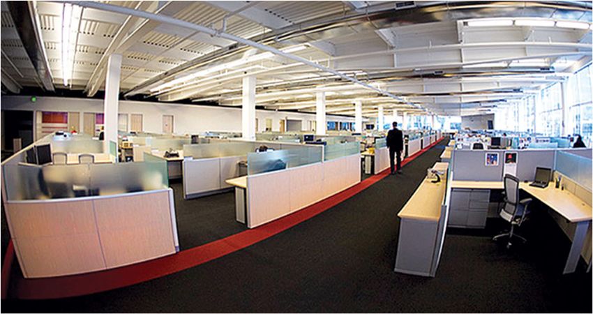
FALCON USER’S GUIDE

                       Figure 1-1: SpaceX vehicles are designed for high cross-platform commonality
The Falcon family has conducted successful flights to the International Space Station (ISS), low Earth orbit (LEO), highly
elliptical orbit (HEO), geosynchronous transfer orbit (GTO), and Earth-escape trajectories. A partial flight manifest for the
Falcon program can be found at www.spacex.com/missions.

Reusability is an integral part of the Falcon program. SpaceX pioneered reusability with the first re-flight of an orbital
class rocket in 2017. As of this writing, SpaceX has re-flown rockets more than fifteen times. In 2018, SpaceX had more
missions launching with a flight-proven rocket than a first flight rocket. By re-flying boosters, SpaceX increases reliability
and improves its designs and procedures by servicing and inspecting hardware as well as incorporating lessons that
can only be learned from flight.

       FALCON LAUNCH VEHICLE SAFETY
The Falcon launch vehicles were designed from the beginning to meet NASA human-rated safety margins. We continue
to push the limits of rocket technology as we design the safest crew transportation system ever flown while
simultaneously advancing toward fully reusable launch vehicles. Our emphasis on safety has led to advancements such
as increased structural factors of safety, greater redundancy, and rigorous fault mitigation. Because SpaceX produces
one Falcon core vehicle, satellite customers benefit from the high design standards required to safely transport crew.
The major safety features are listed in more detail in

Table 1-1.

                                   © Space Exploration Technologies Corp. All rights reserved.                              2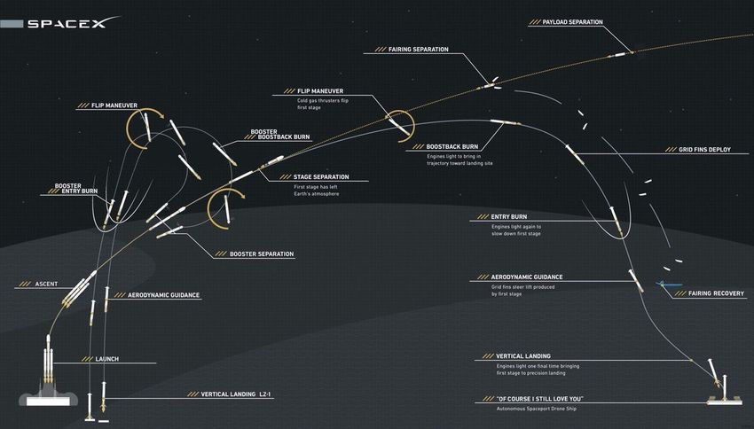
FALCON USER’S GUIDE

                                     Table 1-1: Key safety features of Falcon launch vehicles
    Design/Operations Feature                                      Safety Benefit
    Designed to NASA human-rating margins and safety               Improves reliability for payloads without crew through
    requirements                                                   increased factors of safety, redundancy and fault
                                                                   mitigation
    Horizontal manufacturing, processing and integration           Reduces work at height during numerous
                                                                   manufacturing, processing and integration procedures,
                                                                   and eliminates many overhead operations
    All-liquid propulsion architecture; fuel and oxidizer are      Significantly improves safety by eliminating hazardous
    stored separately on the ground and in the vehicle.            ground handling operations required for systems that
    Propellant is not loaded into the vehicle until the vehicle    use solid propellant cores or boosters
    is erected for launch
    Rocket-grade kerosene and liquid oxygen as primary             Reduces health hazards to processing, integration, and
    propellants                                                    recovery personnel compared to systems that use high
                                                                   toxicity primary propellants
    Non-explosive, pneumatic release and separation                Zero-debris separation systems significantly reduce
    systems                                                        orbital debris signature, can be repeatedly tested during
                                                                   the manufacturing process, and eliminate hazardous
                                                                   pyrotechnic devices
    Regular hardware-in-the-loop (HITL) software testing           Complete verification of entire mission profile prior to
                                                                   flight

1.5       FALCON RELIABILITY
A study1 by The Aerospace Corporation found that 91% of known launch vehicle failures in the previous two decades
can be attributed to three causes: engine, avionics and stage separation failures. With this in mind, SpaceX incorporated
key engine, avionics, and staging reliability features for high reliability at the architectural level of Falcon launch vehicles.
Significant contributors to reliability include:

1.5.1       ENGINES
The Merlin engine that powers the Falcon family of launch vehicles is the only new hydrocarbon engine to be successfully
developed and flown in the U.S. in the past 40 years. It has the highest thrust-weight ratio of any boost engine ever made.
The liquid-propelled Merlin powers the Falcon propulsion system. The engine features a reliable turbopump design with
a single shaft for the liquid oxygen pump, the fuel pump, and the turbine. The engine uses a gas generator cycle instead
of the more complex staged combustion cycle. The regeneratively cooled nozzle and thrust chamber use a milled copper
alloy liner that provides large heat flux margins. A pintle injector provides inherent combustion stability.

Engine failure modes are minimized by eliminating separate subsystems where appropriate. For example, the first-stage
thrust vector control system pulls from the high-pressure rocket-grade kerosene system, rather than using a separate
hydraulic fluid and pressurization system. Using fuel as the hydraulic fluid eliminates potential failures associated with
a separate hydraulic system and with the depletion of hydraulic fluid.

The high-volume engine production required to fly 10 Merlin engines (Falcon 9) or 28 engines (Falcon Heavy) on every
launch results in high product quality and repeatability through process control and continuous production. Flying
several engines on each mission also quickly builds substantial engineering data and flight heritage.

During Falcon launch operations, the first stage is held on the ground after engine ignition while automated monitors
confirm nominal engine operation. An autonomous safe shutdown is performed if any off-nominal condition is detected.

1   Chang, I-Shih. “Space Launch Vehicle Reliability,” Aerospace Corporation Publication (2001).

                                     © Space Exploration Technologies Corp. All rights reserved.                               3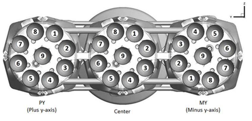
FALCON USER’S GUIDE

Hold-on-pad operations, enabled by the launch vehicle’s all-liquid propulsion architecture and autonomous countdown
sequence, significantly reduce risks associated with engine start-up failures and underperformance.

By employing multiple first-stage engines, SpaceX offers the world’s first evolved expendable launch vehicle (EELV)-
class system with engine-out capability through much of first-stage flight. System-level vehicle management software
controls the shutdown of engines in response to off-nominal engine indications. Although the likelihood of catastrophic
engine failure is low, and failing engines are designed to be shut down prior to a catastrophic failure, each engine is
housed within its own metal bay to isolate it from neighboring engines.

The second-stage Merlin Vacuum engine uses a fixed, non-deploying expansion nozzle, eliminating potential failure
modes in nozzle extension.

1.5.2    AVIONICS
Falcon launch vehicle avionics, and guidance, navigation and control systems use a fault-tolerant architecture that
provides full vehicle single-fault tolerance and uses modern computing and networking technology to improve
performance and reliability. The fault tolerance is achieved either by isolating compartments within avionics boxes or by
using triplicated units of specific components. Both the first and second stages host their own multiple redundant
lithium-ion batteries to minimize the complexity of the electrical interface.

1.5.3    STAGING ARCHITECTURE AND DESIGN
The two-stage Falcon 9 architecture was selected to minimize the number of stage separation events, eliminating
potential failure modes associated with third- and fourth-stage separations, as well as potential engine deployment and
ignition failure modes in the third and fourth stages. Falcon Heavy uses the same stage architecture as Falcon 9 with
the addition of two separating side cores.

The Falcon second-stage and Falcon Heavy side-boosters restraint, release, and separation systems use pneumatic
devices that provide low-shock release and positive force separation over a comparatively long stroke. The pneumatic
system allows for acceptance and functional testing of the actual flight hardware, which is not possible with a traditional
explosives-based separation system.

For each Falcon launch vehicle, SpaceX performs an exhaustive series of tests from the component to the vehicle
system level. The test program includes component-level flight acceptance and workmanship testing, structures load
and proof testing, flight system and propulsion subsystem-level testing, full first- and second-stage testing up to full
system testing (including first- and second-stage static fire testing), as well as a static fire test on the launch pad. In
addition to testing environmental extremes (plus margin), flight critical and workmanship sensitive hardware are tested
to account for off-nominal conditions. For example, stage separation tests are performed for off-nominal cases with
respect to geometrical misalignment, anomalous timing and sequencing.

The Falcon first stage is designed to survive atmospheric entry and to be recovered, handling both the rigors of the
ascent portion of the mission and the loads of the recovery portion. Stage recoverability also provides a unique
opportunity to examine recovered hardware and assess design and material selection in order to continually improve
Falcon 9 and Falcon Heavy.

1.6     PRICING
The standard price for Falcon 9 and Falcon Heavy launch services can be found at www.spacex.com/about/capabilities.
Pricing includes range services, standard payload integration and third-party liability insurance. Please see Section 7.3
for a complete description of standard services. Nonstandard services are also available.

                                  © Space Exploration Technologies Corp. All rights reserved.                            4
FALCON USER’S GUIDE
2 VEHICLES
Descriptions and performance information in this user’s guide are for the Falcon 9 and Falcon Heavy fairing
configuration; please contact SpaceX for information about Dragon launch capabilities. Table 2-1 provides additional
details on Falcon 9 and Falcon Heavy dimensions and design characteristics.
FALCON 9 VEHICLE OVERVIEW
Falcon 9 (Figure 2-1) is a two-stage launch vehicle powered by liquid
oxygen (LOX) and rocket-grade kerosene (RP-1). The vehicle is designed,
built and operated by SpaceX. Falcon 9 can be flown with a fairing or with
a SpaceX Dragon spacecraft. All first- and second-stage vehicle systems
are the same in the two configurations; only the payload interface to the
second stage changes between the fairing and Dragon configurations.
Falcon 9 was updated in the summer of 2015 to a Full Thrust
configuration from its previous v1.1 configuration (flown from 2013 –
summer 2015). Falcon 9 underwent further updates and first flew its Full
Thrust Block 5 configuration in spring 2018. The Falcon 9 Block 5
architecture focused on improving performance, reliability, and life of the
vehicle, as well as ensuring the vehicle’s ability to meet critical
government crewed and non-crewed missions. Engine performance on
both stages was improved, releasing additional thrust capability.
Thermal protection shielding was modified to support rapid recovery and
refurbishment. Avionics designs, thrust structures, and other
components were upgraded for commonality, reliability, and
performance.
FALCON HEAVY VEHICLE OVERVIEW
Falcon Heavy (Figure 2-2) is a two-stage, heavy-lift launch vehicle
powered by LOX and RP-1. It can transport more payload mass into LEO
or GTO than any other launch vehicle currently in operation.
Falcon Heavy is the most powerful launch vehicle in operation with more
than 5.1 million pounds of thrust at liftoff. Falcon Heavy builds on the
proven, highly reliable design of Falcon 9. Falcon Heavy’s first-stage is
comprised of three Falcon 9 first stages with enhancements provided to
strengthen the cores. Furthermore, Falcon Heavy utilizes the same
second stage and same payload fairing as flown on Falcon 9, fully
benefitting from the flight heritage provided by Falcon 9 flights. This
commonality has also minimized infrastructure unique to the vehicle.
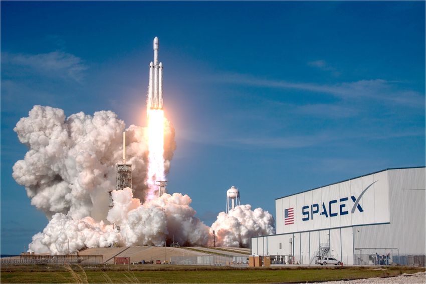
SpaceX first launched the Falcon Heavy vehicle in February of 2018. Figure 2-1: Falcon 9 overview
© Space Exploration Technologies Corp. All rights reserved. 5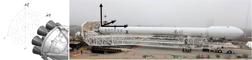
FALCON USER’S GUIDE

                Figure 2-2: The Falcon Heavy demonstration mission launched from KSC on February 6, 2018
The first stage is comprised of three cores: a center core and two side boosters (the first stage of Falcon 9 is used as a
side booster); each core has nine Merlin 1D (M1D) engines. Each of the 27 first stage engines produces 190,000 lbf of
thrust at sea level, for a total of 5,130,000 lbf of thrust at liftoff. The two side boosters are connected to the center core
at the base engine mount and at the forward end of the LOX tank on the center core.

With nine engines in each first-stage core, Falcon Heavy has propulsion redundancy – unlike any other heavy-lift launch
system. The launch vehicle monitors each engine individually during ascent and can, if necessary, preemptively
command off-nominal engines, provided the minimum injection success criteria are achievable with the remaining
engines. This engine-out reliability provides propulsion redundancy throughout first-stage ascent – a feature unique to
Falcon launch vehicles.

       STRUCTURE AND PROPULSION
The first-stage propellant tank walls of the Falcon vehicles are made from an aluminum lithium alloy. Tanks are
manufactured using friction stir welding—the highest strength and most reliable welding technique available. An
insulated common dome separates the LOX and RP-1 tanks, and an insulated transfer tube carries LOX through the
center of the RP-1 tank to the engine section. Four grid fins near the top of the first stage along with four deployable legs
at the base are nominally flown to support recovery operations.

Nine SpaceX Merlin engines power the Falcon 9 first stage with up to 854 kN (190,000 lbf) thrust per engine at sea level,
for a total thrust of 7,686 kN (1.71 million lbf) at liftoff. The first-stage engines are configured in a circular pattern, with
eight engines surrounding a center engine.

Twenty-seven SpaceX Merlin engines power the Falcon Heavy first stages for a total thrust of 5,130,000 lbf at liftoff. The
figure below shows the nomenclature for the center core and side boosters (center, plus y-axis and minus y-axis.)

                                   © Space Exploration Technologies Corp. All rights reserved.                                6
FALCON USER’S GUIDE
Structurally, the plus y-axis and minus y-axis boosters are identical. The center core consists of thicker tank walls and
carries the booster separation system. The z axis points to zenith when the vehicle is horizontal.
Figure 2-3: Falcon Heavy first-stage engine layout
After engine start, Falcon vehicles are held down until all vehicle systems are verified as functioning normally before
release for liftoff.
The Falcon vehicles’ interstage, which connects the first and second stages, is a composite structure consisting of an
aluminum honeycomb core surrounded by carbon fiber face sheet plies. The interstage is fixed to the forward end of the
first-stage tank. The stage separation system is located at the forward end of the interstage and interfaces to the second-
stage.
The second-stage tank for Falcon vehicles is a shorter version of the first-stage tank and uses most of the same
materials, construction, tooling and manufacturing techniques as the first-stage tanks. A single Merlin Vacuum (MVac)
engine powers the second stage, using a fixed 165:1 expansion nozzle. For added reliability of restart, the engine contains
dual redundant triethylaluminum-triethylborane (TEA-TEB) pyrophoric igniters. In addition, the second stage contains a
cold nitrogen gas (GN2) attitude control system (ACS) for pointing and roll control. The GN2 ACS is more reliable and
produces less contamination than a propellant-based reaction control system.
Table 2-1: Falcon dimensions and characteristics
Characteristic First Stage Core Second Stage
Structure
Height 70 m (229 ft) (including both stages, interstage and fairing)
Diameter 3.66 m (12 ft) 3.66 m (12 ft)
Type LOX tank – monococque; LOX tank – monococque
Fuel tank – skin and stringer Fuel tanks – skin and stringer
Material Aluminum lithium skin; aluminum domes
Propulsion
Engine type Liquid, gas generator Liquid, gas generator
Engine designation Merlin 1D (M1D) MVac
Engine designer SpaceX SpaceX
Engine manufacturer SpaceX SpaceX
Number of engines 9 1
Propellant Liquid oxygen/kerosene (RP-1) Liquid oxygen/kerosene (RP-1)
Thrust (stage total) 7,686 kN (sea level) (1,710,000 lbf) 981 kN (Vacuum) (220,500 lbf)
Propellant feed system Turbopump Turbopump
Throttle capability Yes (190,000 lbf to 108,300 lbf sea level) Yes (220,500 lbf to 140,679 lbf)
© Space Exploration Technologies Corp. All rights reserved. 7FALCON USER’S GUIDE
Characteristic First Stage Core Second Stage
Restart capability Yes Yes
Tank pressurization Heated helium Heated helium
Ascent attitude control
Pitch, yaw Gimbaled engines Gimbaled engine/nitrogen gas
thrusters
Roll Gimbaled engines Nitrogen gas thrusters
Coast attitude control Nitrogen gas thrusters Nitrogen gas thrusters
(recovery only)
Operations
Shutdown process Commanded shutdown Commanded shutdown
Stage separation system Pneumatically actuated N/A
separation mechanism
RETENTION, RELEASE AND SEPARATION SYSTEMS
The first and second stages are mated by mechanical latches at three points between the top of the interstage and the
base of the second-stage fuel tank. After the first-stage engines shut down, a high-pressure helium circuit is used to
release the latches via redundant actuators. The helium system also preloads four pneumatic pushers, which provide a
positive-force for stage separation after latch release. This includes a redundant center pusher to further decrease the
probability of re-contact between the stages following separation.
The two halves of the fairing are fastened by mechanical latches along the fairing vertical seam. To deploy the fairing, a
high-pressure helium circuit releases the latches, and four pneumatic pushers facilitate positive-force deployment of the
two halves. The use of all-pneumatic separation systems provides a benign shock environment, allows acceptance and
preflight testing of the actual separation system hardware, and minimizes debris created during separation.
For Falcon Heavy, the fundamental purpose of the side cores is to apply axial force to the center core during ascent and
increase the impulse delivered to second stage before stage separation. The timing of the shutdown for the Falcon
Heavy side cores can be tailored for each mission to ensure that the proper impulse is delivered. Each side core is
structurally connected to the center core at forward and aft locations. Two pusher separation mechanisms (lengthened
versions of the stage separation mechanisms) connect the forward ends of each side core to the center core, fastening
the top of the LOX tank in the center core to the side cores. They maintain the connection during ascent and then actively
jettison the side cores following side core shutdown. Two more pusher separation mechanisms connect the aft ends of
each side core to the center core and are used to laterally force the base of the side cores from the center core following
the side core shut down.
AVIONICS, AND GUIDANCE, NAVIGATION AND CONTROL
Falcon avionics feature a flight-proven, three-string, fault-tolerant architecture that has been designed to human-rating
requirements. Avionics include flight computers, Global Positioning System (GPS) receivers, inertial measurement units,
SpaceX-designed and manufactured controllers for vehicle control (propulsion, valve, pressurization, separation and
payload interfaces), a network backbone, S-band transmitters and a C-band transponder for range safety tracking. The
S-band transmitters are used to transmit telemetry and video to the ground, from both the first and second stages, even
after stage separation.
Our launch vehicles are equipped with an autonomous flight termination system to limit the potential damage caused
by a launch vehicle malfunction. The system terminates the flight of the vehicle automatically if mission rules are
violated.
COORDINATE FRAME
Falcon vehicles use a right-hand X-Y-Z coordinate frame centered 440.69 cm (173.5 in.) aft of the first-stage radial engine
gimbal, with +X aligned with the vehicle long axis and +Z opposite the transporter-erector strongback (Figure 2-4). X is
© Space Exploration Technologies Corp. All rights reserved. 8FALCON USER’S GUIDE
the roll axis, Y is the pitch axis, and Z is the yaw axis. Additional coordinate frames may be defined with reference to the
payload interface (Section 5.1.1) for specific missions.
Figure 2-4: Falcon vehicle coordinate frame
© Space Exploration Technologies Corp. All rights reserved. 9FALCON USER’S GUIDE
3 PERFORMANCE
AVAILABLE INJECTION ORBITS
SpaceX launch services are offered at its Cape Canaveral Air Force Station, Kennedy Space Center, and Vandenberg Air
Force Base launch sites. Together, Cape Canaveral Air Force Station and Kennedy Space Center are referred to herein
as the Eastern Range. Additional launch facilities are currently under development in South Texas (Section 6).
Table 3-1 describes the typical injection orbits available from our operational launch sites. (As other launch sites are
activated, this User’s Guide will be updated.)
Table 3-1: Falcon 9 and Falcon Heavy launch services
Insertion Orbit Inclination Range Vehicle Launch Site(s) Mass Capability
LEO 28.5 – 51.6 deg Falcon 9 or Falcon Eastern Range
Heavy
LEO polar/ 66 – 145 deg Falcon 9 Vandenberg
SSO Contact SpaceX
GTO Up to 28.5 deg Falcon 9 or Falcon Eastern Range for performance
Heavy details
GSO Up to 28.5 deg Falcon Heavy Eastern Range
Earth escape N/A Falcon 9 or Falcon Vandenberg or
Heavy Eastern Range
Launch services to a range of low Earth orbits are available, including services to low-inclination orbits through high-
inclination and sun-synchronous orbits (SSO). Falcon vehicles can provide either two-burn or direct-inject launch
services: two-burn mission profiles optimize vehicle performance, while direct-inject mission profiles offer reduced
mission duration and require only a single start of the second-stage engine. LEO missions to a 51.6 deg inclination or
lower are flown from the Eastern Range; LEO missions to higher inclinations are flown from Vandenberg Air Force Base.
Launch services to inclinations lower than 28.5 deg are available from the Eastern Range, but they incur a performance
penalty.
Launch services to a range of geosynchronous transfer orbits and other high-altitude orbits are available, including
standard GTO, sub-GTO for heavy payloads, and supersynchronous injection. A perigee altitude of 185 km (100 nmi)
is baselined for GTO; higher perigee values may be provided with a performance penalty. Currently, all GTO missions are
flown from the Eastern Range.
Launch services directly into geosynchronous orbit (GSO) are available from Kennedy Space Center via Falcon Heavy.
The satellite is placed into a circular orbit directly above or below GSO to allow it to phase into its correct orbital position.
Launch services to a range of Earth escape orbits are available. Customers may also utilize a customer-supplied kick-
stage to achieve higher escape energy (C3) performance, based on mission requirements. Earth escape missions are
typically flown from the Eastern Range.
MASS-TO-ORBIT CAPABILITY
Mass-to-orbit capabilities for the Falcon 9 and Falcon Heavy fairing configuration are available upon request.
© Space Exploration Technologies Corp. All rights reserved. 10FALCON USER’S GUIDE
MASS PROPERTIES
Figure 3-1: SpaceX payload attach fitting
The payload attach fitting (PAF) converts the diameter of the launch vehicle to a (typical) standard 1575-mm (62.01 in.)
bolted interface (Figure 3-1). Payloads should comply with the mass properties limitations given in Figure 3-2. Payloads
in excess of the figure can be accommodated as a mission unique service. Payload mass properties should be assessed
for all items forward of the payload attach fitting 1575-mm (62.01 in.) bolted interface (Section 5.1.1), including any
mission-unique payload adapters and separation systems. Mass property capabilities may be further constrained by
mission-unique payload adapters, dispensers or separation systems.
SpaceX can also provide a payload attach fitting with a wider interface. Please contact SpaceX for more details.
© Space Exploration Technologies Corp. All rights reserved. 11FALCON USER’S GUIDE
Falcon PAF Capability
7000
Payload CG Height from SIS Interface [mm]
6000
5000
4000
3000
2000
1000
0
0 2000 4000 6000 8000 10000 12000
Payload Mass, including Adapter [kg]
Figure 3-2: Allowable center-of-gravity height above the 1575-mm plane
SpaceX requires that customers verify the mass properties of their system through measurement before shipping it to
the launch site. The company may request insight into relevant analyses and testing performed for satellite qualification,
acceptance and interface verification. Falcon vehicles may be able to accommodate payloads with characteristics
outside the limitations indicated in this section. Please contact SpaceX with your mission-unique requirements.
LAUNCH WINDOWS
Falcon launch vehicles can launch any day of the year, at any time of day, subject to environmental limitations and
constraints as well as range availability and readiness. Launch window times and durations are developed specifically
for each mission. Customers benefit from recycle operations, maximizing launch opportunities within the launch window
(Section 8.5.6).
FLIGHT ATTITUDE
Falcon 9 and Falcon Heavy can provide payload pointing and roll control during long-duration coast phases for sun
avoidance and thermal control. If requested, the Falcon second stage will point the X-axis of the launch vehicle to a
customer-specified attitude and perform a passive thermal control roll of up to ±1.5 deg/sec around the launch vehicle
X-axis, held to a local vertical/local horizontal (LVLH) roll attitude accuracy of ±5 deg.
SEPARATION ATTITUDE AND ACCURACY
Falcon launch vehicles offer 3-axis attitude control or spin-stabilized separation as a standard service. For inertial
separation, the vehicle will point the second stage and payload to the desired LVLH attitude and minimize attitude rates.
For spin-stabilized separation, the Falcon launch vehicle will point the second stage and payload to the desired LVLH
attitude and initiate a spin about the launch vehicle X-axis at a customer-specified rate dependent upon payload mass
properties. Standard pre-separation attitude and rate accuracies are developed as a mission-specific standard service.
More information about separation attitude and rate accuracy is available from SpaceX upon request.
© Space Exploration Technologies Corp. All rights reserved. 12FALCON USER’S GUIDE
MULTIPLE PAYLOADS
Falcon 9 and Falcon Heavy can launch multiple satellites on a single mission, with the customer responsible for the
integration of the multiple payloads. As a liquid-propellant launch vehicle with restart capability, Falcon launch vehicles
also provide the flexibility to deploy each satellite into a different orbit, performance allowing.
Falcon launch vehicles can accommodate a broad range of dispenser systems including multi-payload systems, dual-
payload attach fittings and mission-unique adapters. SpaceX can develop and provide such adapters and dispensers if
desired, as a nonstandard service, or can integrate third-party systems. Please contact SpaceX with your mission-unique
requirements.
SECONDARY PAYLOADS
SpaceX typically reserves the right to manifest secondary payloads aboard Falcon missions on a non-interference basis.
Secondary payloads may be manifested on a variety of secondary payload adapters including an Evolved Expendable
Launch Vehicle (EELV) Secondary Payload Adapter (ESPA) ring, a SpaceX-developed Surfboard, or other mission-unique
secondary deployment structures.
Please contact SpaceX or a secondary payload broker for information regarding flight opportunities, interface
requirements and pricing for secondary payloads.
© Space Exploration Technologies Corp. All rights reserved. 13FALCON USER’S GUIDE
4 ENVIRONMENTS
Falcon 9 and Falcon Heavy have been designed to provide as benign a payload environment as possible, via the use of
all-liquid propulsion, a single staging event, deeply throttleable engines and pneumatic separation systems. The
environments presented below reflect typical mission levels for Falcon 9 and Falcon Heavy; mission-specific analyses
will be performed and documented in an interface control document for each contracted mission.
TRANSPORTATION ENVIRONMENTS
SpaceX recommends using the quasi-static limit load factors provided by NASA-HDBK-7005 (Table 4-1). SpaceX has
quantified the maximum predicted environments experienced by the payload during transportation. Transportation will
be accomplished by two wheeled vehicles: a payload transporter from the payload processing facility to the hangar, and
the launch vehicle transporter-erector from the hangar to the launch pad. It is expected that transportation environments
will be enveloped by the flight environments in Section 4.3.
Table 4-1: Recommended quasi-static load factors for transportation
Longitudinal Lateral Vertical
Transportation Method Load (g) Load (g) Load (g)
Slow-moving dolly (expected ground transport loads) ± 1.0 ± 0.75 ± 2.0
TEMPERATURE, HUMIDITY AND CLEANLINESS
The standard service temperature, humidity and cleanliness environments during various processing phases are
provided in Table 4-2. SpaceX can accommodate environments outside the standard service, e.g. ISO Class 7 (Class
10,000) cleanroom cleanliness. Please contact SpaceX for details.
Conditioned air will be disconnected for a short duration during rollout to the pad. Spacecraft environmental
temperatures will be maintained above the dew point of the supply air at all times. A nitrogen purge is available as a
nonstandard service. The payload attach fitting (PAF) and fairing surface are cleaned to Visibly Clean-Highly Sensitive,
achieving a residue level between A/5 and A/2 and particulate between 300-500 micron, per IEST-STD-CC1246D.
Table 4-2: Temperature and cleanliness environments
Flow
Approx. Cleanliness Rate
Phase Control System Duration Temp. °C (°F) Humidity (class) (cfm)
Spacecraft Payload 3 weeks 21 ± 3 (70 ± 5) CCAFS/KSC: 100,000 N/A
processing processing 45% ± 15%
facility heating, VAFB:
ventilation and air 50% ± 15%
conditioning
(HVAC)
Propellant Facility heating, 3 days 21 ± 3 (70 ± 5) CCAFS/KSC: 100,000 N/A
conditioning ventilation and air 45% ± 15% (Class 8)
conditioning VAFB:
(HVAC) 50% ± 15%
Spacecraft Facility heating, Mission- 21 ± 3 (70 ± 5) CCAFS/KSC: 100,000 N/A
propellant ventilation and air Unique 45% ± 15% (Class 8)
loading conditioning VAFB:
(HVAC) 50% ± 15%
Transport to Transport trailerFALCON USER’S GUIDE
Flow
Approx. Cleanliness Rate
Phase Control System Duration Temp. °C (°F) Humidity (class) (cfm)
Encapsulated Ducted supply 1 week 21 ± 3 (70 ± 5) CCAFS/KSC: 10,000 1,000
in hangar from hangar 45% ± 15% (Class 7)
facility HVAC VAFB: (supply air
50% ± 15% cleanliness)
Encapsulated None 30-60 min N/A N/A 10,000 N/A
roll-out to pad (Class 7)
Encapsulated Pad airFALCON USER’S GUIDE
7
0.5, 6
6
5
0.5, 4
4
Axial Acceleration (g)
2, 3.5
3
2
1
0
‐1 0.5, ‐1.5
2, ‐1.5
‐2 0.5, ‐2
‐3
‐3 ‐2 ‐1 0 1 2 3
Lateral Acceleration (g)
Figure 4-1: Falcon 9 and Falcon Heavy payload design load factors for “standard” mass (over 4,000 lb)
4.3.1.2 FALCON 9 LOADS – LIGHT PAYLOAD MASS
Figure 4-2 shows the Falcon 9 design load factors for lighter payloads (less than 4,000 lb). However, for ultra-light
payloads (~2,000 lb or less), coordination with SpaceX mission management is required, since these load factors may
not be adequate to design the payload. Actual spacecraft loads, accelerations and deflections are a function of both the
launch vehicle and payload structural dynamic properties and can only be accurately determined via a coupled loads
analysis.
© Space Exploration Technologies Corp. All rights reserved. 16FALCON USER’S GUIDE
F9 Design Load Factors F9 Design Load Factors, Payloads < 4,000 lb
10
2, 8.5
8
6
Axial Acceleration (g)
2, 4 3, 4
4
2
0
3, ‐1.5
‐2
2, ‐1.5
‐4
2, ‐4
‐6
‐4 ‐3 ‐2 ‐1 0 1 2 3 4
Lateral Acceleration (g)
Figure 4-2: Falcon 9 payload design load factors, light mass (under 4,000 lb)
4.3.1.3 FALCON HEAVY LOADS – LIGHT PAYLOAD MASS
Please contact SpaceX for more information.
4.3.2 SINE VIBRATION
Maximum predicted sinusoidal vibration environments represent the levels at the top of the payload attach fitting for
Q=20 through Q=50, and envelope all stages of flight. Maximum predicted sinusoidal vibration environments for Falcon
9 and Falcon Heavy are shown in Figure 4-3 and Figure 4-4. These environments represent the vibration levels at the top
of the payload attach fitting for Q=20 through Q=50, and envelope all stages of flight. Since SpaceX accommodates a
variety of payloads, results of coupled loads analysis will be used to modify these levels, if necessary, to reflect the levels
at the payload interface.
© Space Exploration Technologies Corp. All rights reserved. 17FALCON USER’S GUIDE
Figure 4-3: Maximum axial equivalent sine environment for Falcon 9 and Falcon Heavy
© Space Exploration Technologies Corp. All rights reserved. 18FALCON USER’S GUIDE
1
Applicable for Q20
0.9
0.8
0.7
0.6
Acceleration (g)
0.5
0.4
0.3
Frequency (Hz) Acceleration (g)
5 0.5
0.2 85 0.5
100 0.6
0.1
0
0 10 20 30 40 50 60 70 80 90 100
Frequency (Hz)
Figure 4-4: Maximum lateral equivalent sine environment for Falcon 9 and Falcon Heavy
4.3.3 ACOUSTIC
During flight, the payload will be subjected to a varying acoustic environment. Levels are highest near liftoff and during
transonic flight, due to aerodynamic excitation. The acoustic environment, defined as the spatial average and derived at
a P95/50 level, is shown by both full and third-octave curves.
4.3.3.1 FALCON 9 ACOUSTICS
Figure 4-5 and Table 4-3 provide the Falcon 9 third-octave maximum predicted acoustic environment for typical
payloads, while Figure 4-6 and Table 4-4 provide the full-octave maximum predicted acoustic environment. Levels are
shown for both Cape Canaveral (SLC-40 and LC-39A) and Vandenberg (SLC-4E) launch sites respectively. Predicted
acoustic levels for a specific mission will depend on the payload’s size and volume with smaller payloads generally
having lower acoustic levels. Margin for qualification testing or for payloads larger than 60% volume fill is not included
in the curves below.
© Space Exploration Technologies Corp. All rights reserved. 19You can also read