KBox A-203 - USER GUIDE - Diamond Point International
←
→
Page content transcription
If your browser does not render page correctly, please read the page content below
USER GUIDE
KBox A-203
Doc. User Guide, Rev. 1.0
Doc. ID: 1064-9559
www.kontron.com // 1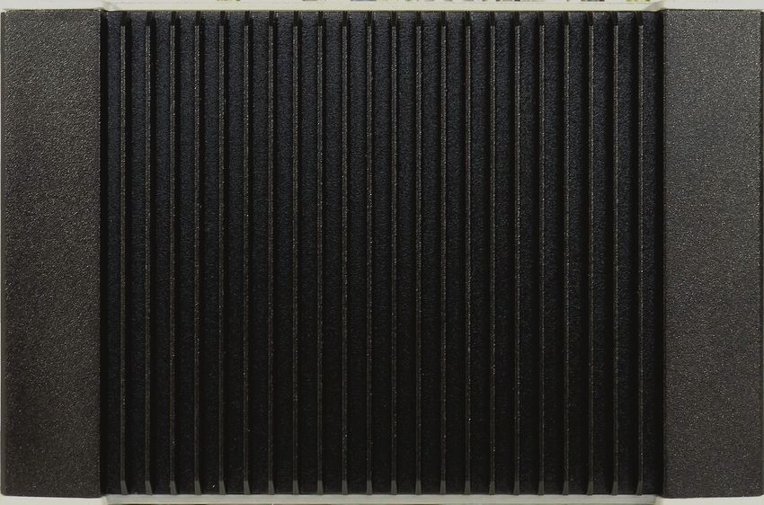
KBox A-203 – User Guide, Rev. 1.0

                  This page has been intentionally left blank

www.kontron.com                                                                              // 2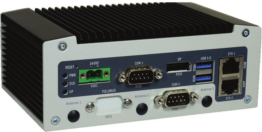
KBox A-203 – User Guide, Rev. 1.0 KBOX A-203 - USER GUIDE Disclaimer Kontron would like to point out that the information contained in this user guide may be subject to alteration, particularly as a result of the constant upgrading of Kontron products. This document does not entail any guarantee on the part of Kontron with respect to technical processes described in the user guide or any product characteristics set out in the user guide. Kontron assumes no responsibility or liability for the use of the described product(s), conveys no license or title under any patent, copyright or mask work rights to these products and makes no representations or warranties that these products are free from patent, copyright or mask work right infringement unless otherwise specified. Applications that are described in this user guide are for illustration purposes only. Kontron makes no representation or warranty that such application will be suitable for the specified use without further testing or modification. Kontron expressly informs the user that this user guide only contains a general description of processes and instructions which may not be applicable in every individual case. In cases of doubt, please contact Kontron. This user guide is protected by copyright. All rights are reserved by Kontron. No part of this document may be reproduced, transmitted, transcribed, stored in a retrieval system, or translated into any language or computer language, in any form or by any means (electronic, mechanical, photocopying, recording, or otherwise), without the express written permission of Kontron. Kontron points out that the information contained in this user guide is constantly being updated in line with the technical alterations and improvements made by Kontron to the products and thus this user guide only reflects the technical status of the products by Kontron at the time of publishing. Brand and product names are trademarks or registered trademarks of their respective owners. ©2019 by Kontron S&T AG Kontron S&T AG Lise-Meitner-Str. 3-5 86156 Augsburg Germany www.kontron.com www.kontron.com // 3
KBox A-203 – User Guide, Rev. 1.0

Intended Use
THIS DEVICE AND ASSOCIATED SOFTWARE ARE NOT DESIGNED, MANUFACTURED OR INTENDED FOR USE
OR RESALE FOR THE OPERATION OF NUCLEAR FACILITIES, THE NAVIGATION, CONTROL OR
COMMUNICATION SYSTEMS FOR AIRCRAFT OR OTHER TRANSPORTATION, AIR TRAFFIC CONTROL, LIFE
SUPPORT OR LIFE SUSTAINING APPLICATIONS, WEAPONS SYSTEMS, OR ANY OTHER APPLICATION IN A
HAZARDOUS ENVIRONMENT, OR REQUIRING FAIL-SAFE PERFORMANCE, OR IN WHICH THE FAILURE OF
PRODUCTS COULD LEAD DIRECTLY TO DEATH, PERSONAL INJURY, OR SEVERE PHYSICAL OR
ENVIRONMENTAL DAMAGE (COLLECTIVELY, "HIGH RISK APPLICATIONS").
You understand and agree that your use of Kontron devices as a component in High Risk Applications is entirely at
your risk. To minimize the risks associated with your products and applications, you should provide adequate design
and operating safeguards. You are solely responsible for compliance with all legal, regulatory, safety, and security
related requirements concerning your products. You are responsible to ensure that your systems (and any Kontron
hardware or software components incorporated in your systems) meet all applicable requirements. Unless otherwise
stated in the product documentation, the Kontron device is not provided with error-tolerance capabilities and cannot
therefore be deemed as being engineered, manufactured or setup to be compliant for implementation or for resale as
device in High Risk Applications. All application and safety related information in this document (including application
descriptions, suggested safety measures, suggested Kontron products, and other materials) is provided for reference
only.

www.kontron.com                                                                                                      // 4
KBox A-203 – User Guide, Rev. 1.0

Revision History

 Revision          Brief Description of Changes                         Date of Issue                        Author/
                                                                                                             Editor
 0.1               Initial Issue                                        2019-Jan-16                          MK

Terms and Conditions
Kontron warrants products in accordance with defined regional warranty periods. For more information about
warranty compliance and conformity, and the warranty period in your region, visit http://www.kontron.com/terms-
and-conditions.
Kontron sells products worldwide and declares regional General Terms & Conditions of Sale, and Purchase Order
Terms & Conditions. Visit http://www.kontron.com/terms-and-conditions.

For contact information, refer to the corporate offices contact information on the last page of this user guide or visit
our website CONTACT US.

Customer Support
Find Kontron contacts by visiting: http://www.kontron.com/support.

Customer Service
As a trusted technology innovator and global solutions provider, Kontron extends its embedded market strengths into
a services portfolio allowing companies to break the barriers of traditional product lifecycles. Proven product
expertise coupled with collaborative and highly-experienced support enables Kontron to provide exceptional peace of
mind to build and maintain successful products.
For more details on Kontron’s service offerings such as: enhanced repair services, extended warranty, Kontron
training academy, and more visit http://www.kontron.com/support-and-services/services.

Customer Comments
If you have any difficulties using this user guide, discover an error, or just want to provide some feedback, contact
Kontron support. Detail any errors you find. We will correct the errors or problems as soon as possible and post the
revised user guide on our website.

www.kontron.com                                                                                                       // 5
KBox A-203 – User Guide, Rev. 1.0

Symbols
The following symbols may be used in this user guide

                    DANGER indicates a hazardous situation which, if not avoided,
                    will result in death or serious injury.

                    WARNING indicates a hazardous situation which, if not avoided,
                    could result in death or serious injury.

                    NOTICE indicates a property damage message.

                    CAUTION indicates a hazardous situation which, if not avoided,
                    may result in minor or moderate injury.

                    Electric Shock!
                    This symbol and title warn of hazards due to electrical shocks (> 60 V) when touching
                    products or parts of products. Failure to observe the precautions indicated and/or
                    prescribed by the law may endanger your life/health and/or result in damage to your
                    material.

                    ESD Sensitive Device!
                    This symbol and title inform that the electronic boards and their components are sensitive
                    to static electricity. Care must therefore be taken during all handling operations and
                    inspections of this product in order to ensure product integrity at all times.

                    HOT Surface!
                    Do NOT touch! Allow to cool before servicing.

                    Laser!
                    This symbol inform of the risk of exposure to laser beam and light emitting devices (LEDs)
                    from an electrical device. Eye protection per manufacturer notice shall review before
                    servicing.

                    This symbol indicates general information about the product and the user guide.
                    This symbol also indicates detail information about the specific product configuration.

                    This symbol precedes helpful hints and tips for daily use.

www.kontron.com                                                                                                   // 6
KBox A-203 – User Guide, Rev. 1.0

For Your Safety
Your new Kontron product was developed and tested carefully to provide all features necessary to ensure its
compliance with electrical safety requirements. It was also designed for a long fault-free life. However, the life
expectancy of your product can be drastically reduced by improper treatment during unpacking and installation.
Therefore, in the interest of your own safety and of the correct operation of your new Kontron product, you are
requested to conform with the following guidelines.

High Voltage Safety Instructions
As a precaution and in case of danger, the power connector must be easily accessible. The power connector is the
product’s main disconnect device.

                     Warning
                     All operations on this product must be carried out by sufficiently skilled personnel only.

                     Electric Shock!
                     Before installing a non hot-swappable Kontron product into a system always ensure that
                     your mains power is switched off. This also applies to the installation of piggybacks. Serious
                     electrical shock hazards can exist during all installation, repair, and maintenance operations
                     on this product. Therefore, always unplug the power cable and any other cables which
                     provide external voltages before performing any work on this product.
                     Earth ground connection to vehicle’s chassis or a central grounding point shall remain
                     connected. The earth ground cable shall be the last cable to be disconnected or the first
                     cable to be connected when performing installation or removal procedures on this product.

Special Handling and Unpacking Instruction

                     ESD Sensitive Device!
                     Electronic boards and their components are sensitive to static electricity. Therefore, care
                     must be taken during all handling operations and inspections of this product, in order to
                     ensure product integrity at all times.

Do not handle this product out of its protective enclosure while it is not used for operational purposes unless it is
otherwise protected.
Whenever possible, unpack or pack this product only at EOS/ESD safe work stations. Where a safe work station is not
guaranteed, it is important for the user to be electrically discharged before touching the product with his/her hands
or tools. This is most easily done by touching a metal part of your system housing.
It is particularly important to observe standard anti-static precautions when changing piggybacks, ROM devices,
jumper settings etc. If the product contains batteries for RTC or memory backup, ensure that the product is not placed
on conductive surfaces, including anti-static plastics or sponges. They can cause short circuits and damage the
batteries or conductive circuits on the product.

www.kontron.com                                                                                                         // 7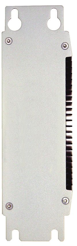
KBox A-203 – User Guide, Rev. 1.0
Lithium Battery Precautions
If your product is equipped with a lithium battery, take the following precautions when replacing the battery.
Danger of explosion if the battery is incorrectly replaced. Examples that shall be considered
include:
Replacement of a battery with an incorrect type that can defeat a safeguard (e.g., in the
case of some lithium battery types);
Disposal of a battery into fire or a hot oven, or mechanically crushing or cutting of a
battery, that can result in an explosion;
Leaving a battery in an extremely high temperature surrounding environment that can
result in an explosion or the leakage of flammable liquid or gas;
A battery subjected to extremely low air pressure that may result in an explosion or the
leakage of flammable liquid or gas.
In case of using an optional Lithium battery, please consider limited operating temperature
to maximum 40°C.
General Instructions on Usage
In order to maintain Kontron’s product warranty, this product must not be altered or modified in any way. Changes or
modifications to the product, that are not explicitly approved by Kontron and described in this user guide or received
from Kontron Support as a special handling instruction, will void your warranty.
This product should only be installed in or connected to systems that fulfill all necessary technical and specific
environmental requirements. This also applies to the operational temperature range of the specific board version
that must not be exceeded. If batteries are present, their temperature restrictions must be taken into account.
In performing all necessary installation and application operations, only follow the instructions supplied by the
present user guide.
Keep all the original packaging material for future storage or warranty shipments. If it is necessary to store or ship
the product then re-pack it in the same manner as it was delivered. Special care is necessary when handling or
unpacking the product. See Special Handling and Unpacking Instruction.
Quality and Environmental Management
Kontron aims to deliver reliable high-end products designed and built for quality, and aims to complying with
environmental laws, regulations, and other environmentally oriented requirements. For more information regarding
Kontron’s quality and environmental responsibilities, visit http://www.kontron.com/about-kontron/corporate-
responsibility/quality-management.
Disposal and Recycling
Kontron’s products are manufactured to satisfy environmental protection requirements where possible. Many of the
components used are capable of being recycled. Final disposal of this product after its service life must be
accomplished in accordance with applicable country, state, or local laws or regulations.
www.kontron.com // 8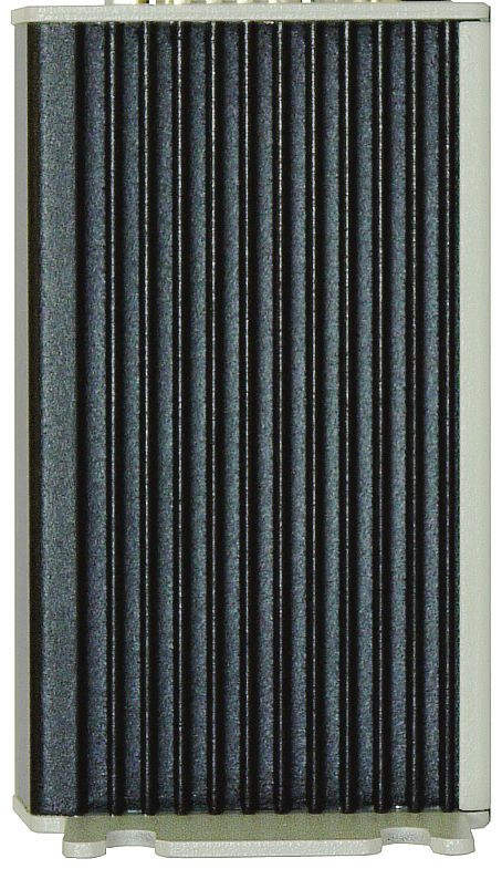
KBox A-203 – User Guide, Rev. 1.0
WEEE Compliance
The Waste Electrical and Electronic Equipment (WEEE) Directive aims to:
Reduce waste arising from electrical and electronic equipment (EEE)
Make producers of EEE responsible for the environmental impact of their products, especially when the product
become waste
Encourage separate collection and subsequent treatment, reuse, recovery, recycling and sound environmental
disposal of EEE
Improve the environmental performance of all those involved during the lifecycle of EEE
Environmental protection is a high priority with Kontron.
Kontron follows the WEEE directive
You are encouraged to return our products for proper disposal.
www.kontron.com // 9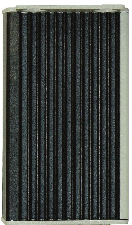
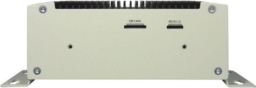
KBox A-203 – User Guide, Rev. 1.0

Table of Contents
Symbols .................................................................................................................................................................................................................6
For Your Safety ...................................................................................................................................................................................................7
High Voltage Safety Instructions .................................................................................................................................................................. 7
Special Handling and Unpacking Instruction ............................................................................................................................................ 7
Lithium Battery Precautions .......................................................................................................................................................................... 8
General Instructions on Usage ..................................................................................................................................................................... 8
Quality and Environmental Management ................................................................................................................................................ 8
Disposal and Recycling.................................................................................................................................................................................... 8
WEEE Compliance...............................................................................................................................................................................................9
Table of Contents.............................................................................................................................................................................................10
List of Tables .....................................................................................................................................................................................................12
List of Figures ....................................................................................................................................................................................................12
1/           General Safety Instructions for IT Equipment .........................................................................................................................14
1.1. Electrostatic Discharge (ESD) ................................................................................................................................................................ 16
1.1.1. Grounding Methods ................................................................................................................................................................................ 16
2/           Electromagnetic Compatibility ..................................................................................................................................................... 17
2.1. Electromagnetic Compatibility (EU).................................................................................................................................................... 17
2.2. FCC Statement (USA) ............................................................................................................................................................................... 17
2.3. EMC Compliance (Canada) .................................................................................................................................................................... 17
3/           Shipment and Unpacking ................................................................................................................................................................18
3.1. Unpacking ....................................................................................................................................................................................................18
3.2. Scope of Delivery ......................................................................................................................................................................................18
3.2.1. Standard ...................................................................................................................................................................................................18
3.2.2. Optional Parts ........................................................................................................................................................................................18
3.3. Type Label and Product Identification............................................................................................................................................... 19
4/           System Overview .............................................................................................................................................................................. 20
4.1. RTC ................................................................................................................................................................................................................. 21
4.1.1. RTC Buffer Time ...................................................................................................................................................................................... 21
4.2. System Expansion Capabilities ............................................................................................................................................................ 21
4.3. Block Diagram of the KBox A-203 ..................................................................................................................................................... 22
4.4. Front Side................................................................................................................................................................................................... 23
4.5. Front Interfaces of the KBox A-203 .................................................................................................................................................. 24
4.5.1. X101 - Power Input Connector .......................................................................................................................................................... 24
4.5.2. Controls and LED Indicators ............................................................................................................................................................. 24
4.5.3. X106/X107 - Ethernet Connectors (ETH) ...................................................................................................................................... 25
4.5.4. X104/X105 - USB 3.0 ........................................................................................................................................................................... 25
4.5.5. X103 - DisplayPort ............................................................................................................................................................................... 25
4.5.6. X102 – Serial Port COM 1 .................................................................................................................................................................... 25
4.5.7. X202 – Serial Port COM 2 (Option) ................................................................................................................................................. 25
4.5.8. X203 - Fieldbus Interface (Option) ................................................................................................................................................ 25
4.6. Left and Right Side View ....................................................................................................................................................................... 26
4.7. Top and Bottom Side View ................................................................................................................................................................... 26
4.8. Rear Side View.......................................................................................................................................................................................... 27
4.8.1. Rear Side View of the KBox A-203 with Vertical Mounting Bracket.................................................................................... 27
4.8.2. Rear Side View of the KBox A-203 as Desktop with Rubber Feet ...................................................................................... 28
4.8.3. Rear Side View of the KBox A-203 with Wallmount Bracket ................................................................................................ 28

www.kontron.com                                                                                                                                                                                                         // 10
KBox A-203 – User Guide, Rev. 1.0

4.9. Optional Parts........................................................................................................................................................................................... 29
4.9.1. DIN Rail Clip (Option) ........................................................................................................................................................................... 29
4.9.2. WLAN (Option) ...................................................................................................................................................................................... 29
5/           Thermal Considerations .................................................................................................................................................................. 31
5.1. Available Processors................................................................................................................................................................................ 31
5.2. Convection Cooling................................................................................................................................................................................... 31
5.3. Minimum System Clearance ................................................................................................................................................................. 31
5.4. Maximum Temperatures ....................................................................................................................................................................... 31
6/           Installation Instructions ................................................................................................................................................................. 32
6.1. System Mounting ..................................................................................................................................................................................... 33
6.2. DC Power Connection ............................................................................................................................................................................. 35
6.2.1. Cabling ...................................................................................................................................................................................................... 35
7/           Starting Up........................................................................................................................................................................................... 36
7.1. Connecting to DC Main Power Supply ............................................................................................................................................... 36
7.2. Operating System and Hardware Component Drivers................................................................................................................ 37
8/           Maintenance and Cleaning ............................................................................................................................................................ 38
9/           Technical Specifications................................................................................................................................................................. 39
9.1. Mechanical Specifications..................................................................................................................................................................... 40
9.1.1. Mechanical Specifications of the KBox A-203 as Desktop ...................................................................................................... 40
9.1.2. Mechanical Specifications of the KBox A-203 with Vertical Mounting Plate .................................................................... 41
9.1.3. Mechanical Specifications of the KBox A-203 with Wallmount Bracket ........................................................................... 42
9.2. Environmental Specifications ............................................................................................................................................................. 43
9.3. CE Directives and Standards................................................................................................................................................................44
10/          Standard Interfaces – Pin Assignments ................................................................................................................................... 45
10.1.1. (X101) Power Input Connector ......................................................................................................................................................... 45
10.1.2. (X106 as ETH 1 and X107 as ETH 2) Ethernet Connectors ...................................................................................................... 45
10.1.3. (X104, X105) USB 3.0 Ports............................................................................................................................................................... 46
10.1.4. (X103) DisplayPort .............................................................................................................................................................................. 46
10.1.5. (X102) Serial Interface COM 1 (RS232/485/422) ..................................................................................................................... 47
10.1.6. (X202) Serial Interface COM 2 (RS232)........................................................................................................................................ 47
11/          uEFI BIOS ..............................................................................................................................................................................................48
11.1. Starting the uEFI BIOS ............................................................................................................................................................................48
11.2. Setup Menus ............................................................................................................................................................................................ 49
11.2.1. Main Setup Menu ................................................................................................................................................................................. 49
11.2.2. Advanced Setup Menu........................................................................................................................................................................ 51
11.2.3. Chipset Setup Menu ............................................................................................................................................................................57
11.2.4. Security Setup Menu .......................................................................................................................................................................... 66
11.2.5. Boot Setup Menu ................................................................................................................................................................................. 69
11.2.6. Save and Exit Setup Menu ................................................................................................................................................................. 71
11.3. Firmware Update .................................................................................................................................................................................... 72
Appendix A: List of Acronyms ..................................................................................................................................................................... 73
About Kontron .................................................................................................................................................................................................. 74

www.kontron.com                                                                                                                                                                                                     // 11
KBox A-203 – User Guide, Rev. 1.0

List of Tables
Table 1: Technical Specifications ................................................................................................................................................................ 39
Table 2: Mechanical Specifications ........................................................................................................................................................... 40
Table 3: Environmental Specifications ..................................................................................................................................................... 43
Table 4: CE Directives and Standards .......................................................................................................................................................44
Table 5: (X101) Power Input Connector .................................................................................................................................................... 45
Table 6: (X106, X107) Ethernet Connectors ............................................................................................................................................. 45
Table 7: (X104, X105) USB 3.0 Port ............................................................................................................................................................. 46
Table 8: (X103) DisplayPort.......................................................................................................................................................................... 46
Table 9: (X102) Serial Interface COM 1 (RS232) ..................................................................................................................................... 47
Table 10: (X202) Serial Interface COM 2 (RS232) .................................................................................................................................. 47
Table 11: Navigation Hot Keys Available in the Legend Bar ............................................................................................................... 48
Table 12: Main Setup Menu Sub-screens and Functions ................................................................................................................... 50
Table 13: Advanced Setup menu Sub-screens and Functions ........................................................................................................... 51
Table 14: Chipset Set > North Bridge Sub-screens and Function .................................................................................................... 58
Table 15: Chipset Set> South Bridge Sub-screens and Functions ................................................................................................... 59
Table 16: Chipset Set> Uncore Configuration Sub-screens and Functions .................................................................................. 60
Table 17: Chipset>South Cluster Configuration Sub-screens and Functions .............................................................................. 62
Table 18: Security Setup Menu Sub-screens and Functions ............................................................................................................. 66
Table 19: Boot Setup Menu Sub-screens and Functions .................................................................................................................... 69
Table 20: Save and Exit Setup Menu Sub-screens and Functions ................................................................................................... 71
Table 21: List of Acronyms (Example) ...................................................................................................................................................... 73

List of Figures
Figure 1: Type Label.......................................................................................................................................................................................... 19
Figure 2: Block Diagram of the KBox A-203............................................................................................................................................ 22
Figure 3: KBox A-203 – Front View ............................................................................................................................................................ 23
Figure 4: X101 - 24VDC power input connector ..................................................................................................................................... 24
Figure 5: Detail - Power button and LED indicators ............................................................................................................................. 24
Figure 6: X203 - Optional FIELDBUS interface ....................................................................................................................................... 25
Figure 7: Right side of the KBox A-203 system ..................................................................................................................................... 26
Figure 8: Left side of the KBox A-203 system ....................................................................................................................................... 26
Figure 9: Top side of the KBox A-203 system ........................................................................................................................................ 26
Figure 10: Bottom side of the KBox A-203 system ............................................................................................................................... 26
Figure 11: Rear side of the KBox A-203 system with vertical mounting plate ............................................................................ 27
Figure 12: Rear side of the KBox A-203 (shown as desktop unit) ................................................................................................... 28
Figure 13: Rear side of the KBox A-203 (shown with vertical/horizontal mounting brackets) ............................................ 28
Figure 14: DIN rail clip mounted to the access cover ........................................................................................................................... 29
Figure 15: DIN rail clip mounted to the rear plate ................................................................................................................................. 29
Figure 16: WLAN (WiFi) antenna ................................................................................................................................................................. 30
Figure 17: Restricted area for mounting around KBox A-203 (desktop side view with antenna) ........................................ 33
Figure 18: Restricted area for mounting around KBox A-203 (front view with vert./horiz. mounting brakets) ............. 34
Figure 19: Power plug terminal ................................................................................................................................................................... 35
Figure 20: Dimensions: Front as desktop ................................................................................................................................................ 40
Figure 21: Dimensions: Front side with antennas and wall/table mounting brackets ............................................................ 40
Figure 22: Dimensions: Left side .................................................................................................................................................................41
Figure 23: Dimensions: Rear side with vertical mounting plate ......................................................................................................41
Figure 24: Dimensions: Detail key hole .....................................................................................................................................................41
Figure 25: Dimensions: Top side (with wall/table mounting brackets) ........................................................................................ 42
Figure 26: Dimensions: front side (with wall/table mounting brackets) ..................................................................................... 42
Figure 27: Detail mounting slide hole (wall/table mounting brackets) ........................................................................................ 42
Figure 28: Main Setup Menu Initial Screen ............................................................................................................................................. 49
Figure 29: Advanced Setup Menu Initial Screen ..................................................................................................................................... 51
Figure 30: Chipset Setup Menu Initial Screen .........................................................................................................................................57

www.kontron.com                                                                                                                                                                                             // 12
KBox A-203 – User Guide, Rev. 1.0

Figure 31: Chipset > North Bridge Menu Initial Screen ........................................................................................................................ 58
Figure 32: Chipset>South Bridge Menu Initial Screen ......................................................................................................................... 59
Figure 33: Chipset>Uncore Configuration Menu Initial Screen......................................................................................................... 60
Figure 34: Chipset>South Cluster Configuration Menu Initial Screen ............................................................................................ 62
Figure 35: Security Setup Menu Initial Screen ....................................................................................................................................... 66
Figure 36: Boot Setup Menu Initial Screen .............................................................................................................................................. 69
Figure 37: Save and Exit Setup Menu Initial Screen .............................................................................................................................. 71

www.kontron.com                                                                                                                                                                        // 13
KBox A-203 – User Guide, Rev. 1.0
1/ General Safety Instructions for IT Equipment
Please read this chapter carefully and take careful note of the instructions, which have been
compiled for your safety and to ensure to apply in accordance with intended regulations. If
the following general safety instructions are not observed, it could lead to injuries to the
operator and/or damage of the product; in cases of nonobservance of the instructions
Kontron is exempt from accident liability, this also applies during the warranty period.
The product has been built and tested according to the basic safety requirements for low voltage (LVD) applications
and has left the manufacturer in safety-related, flawless condition. To maintain this condition and also to ensure safe
operation, the operator must not only observe the correct operating conditions for the product but also the following
general safety instructions:
The product must be used as specified in the product documentation, in which the instructions for safety for
the product and for the operator are described. These contain guidelines for setting up, installation and
assembly, maintenance, transport or storage.
The on-site electrical installation must meet the requirements of the country's specific local regulations.
If a power cable comes with the product, only this cable should be used. Do not use an extension cable to
connect the product.
To guarantee that sufficient air circulation is available to cool the product, please ensure that the ventilation
openings are not covered or blocked. If an air filter is provided, this should be cleaned regularly. Do not place
the system close to heat sources or damp places. Make sure the system is well ventilated.
Only devices or parts which fulfill the requirements of SELV circuits (Safety Extra Low Voltage) as stipulated by
IEC 60950-1 may be connected to the available interfaces.
Before opening the device, make sure that the device is disconnected from the mains.
Switching off the device by its power button does not disconnect it from the mains. Complete disconnection is
only possible if the power cable is removed from the wall plug or from the device. Ensure that there is free and
easy access to enable disconnection.
The device may only be opened for the insertion or removal of add-on cards (depending on the configuration of
the system). This may only be carried out by qualified operators.
If extensions are being carried out, the following must be observed:
All effective legal regulations and all technical data are adhered to.
The power consumption of any add-on card does not exceed the specified limitations.
The current consumption of the system does not exceed the value stated on the product label.
Only original accessories that have been approved by Kontron can be used.
Please note: safe operation is no longer possible when any of the following applies:
The device has visible damages.
The device is no longer functioning.
In this case the device must be switched off and it must be ensured that the device can no longer be operated.
www.kontron.com // 14KBox A-203 – User Guide, Rev. 1.0
Additional safety instructions for DC power supply circuits
To guarantee safe operation of devices with DC power supply voltages larger than 60 volts DC or a power
consumption larger than 240 VA, please observe that:
the device is set up, installed and operated in a room or enclosure marked with “RESTRICTED ACCESS”, if
there are no safety messages on product as safety signs and labels on the device itself.
no cables or parts without insulation in electrical circuits with dangerous voltage or power should be
touched directly or indirectly
a reliable protective earthing connection is provided
a suitable, easily accessible disconnecting device is used in the application (e.g. overcurrent protective
device), if the device itself is not disconnectable
a disconnect device, if provided in or as part of the equipment, shall disconnect both poles simultaneously
interconnecting power circuits of different devices cause no electrical hazards
A sufficient dimensioning of the power cable wires must be selected – according to the maximum electrical
specifications on the product label – as stipulated by IEC 61010-1, IEC 61010-2-201, IEC60950-1 or VDE0100 or
UL508 regulations.
The devices do not generally fulfill the requirements for "centralized DC power systems“ (UL 60950-1, Annex
NAB; D2) and therefore may not be connected to such devices!
Only certified at least IEC 60950-1 compliant main power supply unit shall be connected!
www.kontron.com // 15KBox A-203 – User Guide, Rev. 1.0
1.1. Electrostatic Discharge (ESD)
A sudden discharge of electrostatic electricity can destroy static-sensitive devices or micro-
circuitry.
Therefore proper packaging and grounding techniques are necessary precautions to prevent damage. Always take the
following precautions:
1. Transport boards in ESD-safe containers such as boxes or bags.
2. Keep electrostatic sensitive parts in their containers until they arrive at the ESD-safe workplace.
3. Always be properly grounded when touching a sensitive board, component, or assembly.
4. Store electrostatic-sensitive boards in protective packaging or on antistatic mats.
1.1.1. Grounding Methods
By adhering to the guidelines below, electrostatic damage to the device can be avoided:
1. Cover workstations with approved antistatic material. Always wear a wrist strap connected to workplace. Always
use properly grounded tools and equipment.
2. Use antistatic mats, heel straps, or air ionizers for more protection.
3. Always handle electrostatically sensitive components by their edge or by their casing.
4. Avoid contact with pins, leads, or circuitry.
5. Turn off power and input signals before inserting and removing connectors or connecting test equipment.
6. Keep work area free of non-conductive materials such as ordinary plastic assembly aids and Styrofoam.
7. Use only field service tools which are conductive, such as cutters, screwdrivers, and vacuum cleaners.
8. Always place drives and boards PCB-assembly-side down on the foam.
www.kontron.com // 16KBox A-203 – User Guide, Rev. 1.0
2/ Electromagnetic Compatibility
For detailed information refer to section 9.3 “CE Directives and Standards”.
2.1. Electromagnetic Compatibility (EU)
This product is intended only for use in industrial areas. The most recent version of the EMC guidelines (EMC Directive
2014/30/EU) and/or the German EMC laws apply. If the user modifies and/or adds to the equipment (e.g. installation
of add-on cards) the prerequisites for the CE conformity declaration (safety requirements) may no longer apply.
This is a class A product. In domestic environment this product may cause radio interference
in which case the user may be required to take adequate measures.
2.2. FCC Statement (USA)
This equipment has been tested and found to comply with the limits for a Class A digital device, pursuant to Part 15 of
the FCC Rules. These limits are designed to provide reasonable protection against harmful interference when the
equipment is operated in commercial environment. This equipment generates, uses, and can radiate radio frequency
energy and, if not installed and used in accordance with the instruction manual, may cause harmful interference to
radio communications. Operation of this equipment in residential area is likely to cause harmful interference in which
case the user will be required to correct the interference at his own expense.
2.3. EMC Compliance (Canada)
The method of compliance is self-declaration to Canadian standard ICES-003:
(English): This Class A digital apparatus complies with the Canadian ICES-003.
(French): Cet appareil numérique de la class A est conforme à la norme NMB-003 du Canada.
www.kontron.com // 17KBox A-203 – User Guide, Rev. 1.0
3/ Shipment and Unpacking
Please check that your package is complete, and contains the items below (according to the ordered unit
configuration). If you discover damaged or missing items, please contact your dealer.
3.1. Unpacking
Proceed as follows to unpack the unit:
1. Remove packaging.
2. Do not discard the original packaging. Keep it for future relocation.
3. Check the delivery for completeness by comparing it with your order.
4. Please keep the associated paperwork. It contains important information for handling the unit.
5. Check the contents for visible shipping damage.
6. If you notice any shipping damage or inconsistencies between the contents and your order, please contact
Kontron for help and information.
3.2. Scope of Delivery
3.2.1. Standard
KBox A-203 (corresponding to the ordered system configuration)
Power connector, 2-pin plug (TE Connectivity 796859-2)
General Safety Instructions for IT Equipment
3.2.2. Optional Parts
DIN rail mounting clip
Mini PCIe WLAN (WiFi) card (always factory-installed if orderd) with three antennas (enclosed)
KBox A-203 can optionally be ordered with a factory-installed SSD Kit
Mini PCIe LTE card (always factory-installed if orderd) with one antenna (enclosed)
SD card
Bracket for wall/table mounting
Vertical mounting plate for control cabinet mounting
Rubber feet (self-adhesive)
www.kontron.com // 18KBox A-203 – User Guide, Rev. 1.0
3.3. Type Label and Product Identification
The type label (product name, serial number) of your KBox A-203 system are located on the bottom side of the device
(refer to Figure 1 and Figure 7 pos. 1).
Figure 1: Type Label
KBox A-203
2-A0DL-XXXX
2.1A max.
www.kontron.com // 19KBox A-203 – User Guide, Rev. 1.0
4/ System Overview
The KBox A-203 expands the Kontron line of computers - KBox Series. It is a highly scalable and flexible industrial
computer. Based on the latest Intel Atom® processor of the E3900 series the new wartungsfrei (maintenance-free),
fanless and battery-free KBox A-203 was developed as an intelligent gateway for data-intensive IoT edge
applications.
The KBox A-203 is one of the first Kontron products which is Microsoft® Azure certified. This means the hardware is
tested and verified and can be integrated into Microsoft® Azure IoT Services.
Refer to the information and technical data in the user manual of the installed SMARC sXAL
Module.
The user’s manual of the installed SMARC module can be downloaded from our web page
http://www.kontron.com . Search for the name of the installed module.
The compact KBox A-203 shows a broad range of interfaces which allow a connection on various communication
levels. For local data collection, e.g. link to sensor and machine level, it offers up to two serial ports (RS232/485) and
an optional fieldbus (e.g. Profi Bus). On project base the KBox A-203 can also support wireless standards such as LTE
(4G), GSM (2G/3G) and in future the low-power standard LoRa.
The KBox A-203 supports Security Solution Kontron APPROTECT. It combines a software framework with an
integrated security chip in addition to the TPM 2.0 (Trusted Platform Module) chip to provide comprehensive
protection for the application software.
The KBox A-203 hardware system configuration and the robust construction with excellent mechanical stability offer
the superior qualities of a computer designed for operation in harsh industrial environment. It is a fanless system
based on a compact U-shaped aluminum chassis with cooling fins.
The rated voltage of the mains (+24 V DC) can be found on the type label. The type label is located at the bottom side
of the device. The KBox A-203 may be optionally factory-equipped with an mPCIe WLAN card for two antennas. For
the configuration of your KBox A-203 please follow the ordering options specified in “Configuration Guides – KBox
Series“ on our web site www.kontron.com
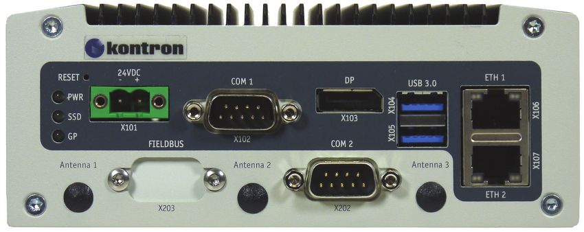
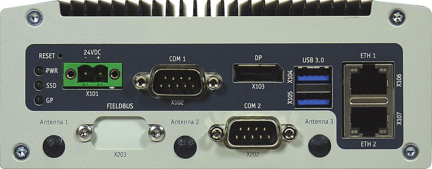
The following interfaces are available with the KBox A-203:
Standard:
24 V DC input power (X101)
DisplayPort (X103)
2x USB 3.0 (X104, X105)
2x Ethernet (X106, X107) : Gigabit Ethernet (10/100/1000)
COM 1 (X102), RS232 (optional: RS422/485)
Reset button
Power LED, SSD LED and GP LED
Optional:
COM 2 (X202), RS232
Fieldbus Connector (X203)
www.kontron.com // 20KBox A-203 – User Guide, Rev. 1.0
The device is designed to be operated in:
Vertical position: (KBox A-203 configuration with vertical mounting plate) mounted inside a control cabinet or
Vertical/horizontal: wall mounted (KBox A-203 configuration with wall mounting bracket) or
Horizontal position: KBox A-203 as desktop unit (equipped with the supplied rubber feet) or
Vertical/horizontal: KBox A-203 DIN Rail mounting (with DIN Rail mounting clip)
When powering on the KBox A-203, make sure that the cooling fins of the chassis (Figure 8,
Figure 9 and Figure 10, pos. 6) are not obstructed (covered) by any objects.
To provide sufficient heat dissipation by the cooling of the device, do not cover the cooling
fins of the
KBox A-203. Do not place any objects on the device. When installing the system, please note
the clearance recommendation in the section 6.1 “System Mounting”.
4.1. RTC
The KBox A-203 comprises a chipset external RTC. This RTC is connected to the SMBus of the processor module. A
RTC of type RV-8564 or compatible is used. To provide a valid date and time when no power is connected to the KBox
A-203, the RTC is equipped with a goldcap buffer.
4.1.1. RTC Buffer Time
The RTC buffer time is depending of the ambient temperature.
If the time is not valid this is indicated by a status bit in the RTC registers. For details see the RV-8564 application
manual.
To get the maximum buffer time it is necessary to have the system a certain time powered
on. This ensures that the buffer capacitors are fully loaded.
The buffer time depends on the ambient temperature and on how long the box is connected
to its power supply.
4.2. System Expansion Capabilities
The KBox A-203 is available in the configurations described in this manual.
If you are interested in a different, customer-specific configuration, feel free to contact Kontron and ask for your
requirements. Contact information can be found on our web site www.kontron.com.
www.kontron.com // 21You can also read