BEAMA GUIDE TO SURGE PROTECTION DEVICES =SPDs SELECTION, APPLICATION AND THEORY - Bringing power to life.
←
→
Page content transcription
If your browser does not render page correctly, please read the page content below
Bringing
                               power to life.

BEAMA GUIDE TO
SURGE PROTECTION DEVICES (SPDs)
SELECTION, APPLICATION AND THEORY

                                    JULY 2018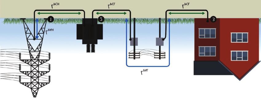
BEAMA is the long established and respected trade association for
the electrotechnical sector. The association has a strong track
record in the development and implementation of standards to
promote safety and product performance for the benefit of
manufacturers and their customers.

This Guide is intended as a practical guide for designers, specifiers
and installers to enable them to comply with surge protection
requirements in BS 7671 Requirements for Electrical Installations –
IET Wiring Regulations – 18th Edition.

This Guide has been produced by BEAMA’s Building Electrical
Systems Portfolio which comprises of major UK manufacturing
companies operating under the guidance and authority of BEAMA,
supported by specialist central services for guidance on European
Single Market, Quality Assurance, Legal and Health & Safety matters.

Details of other BEAMA Guides can be found on the BEAMA
website www.beama.org.uk

DISCLAIMER
This publication is subject to the copyright of BEAMA Ltd. While the information herein has been compiled
in good faith, no warranty is given or should be implied for its use and BEAMA hereby disclaims any liability
that may arise from its use to the fullest extent permitted under applicable law..

© BEAMA Ltd 2018
Copyright and all other intellectual property rights in this document are the property of BEAMA Ltd. Any
party wishing to copy, reproduce or transmit this document or the information contained within it in any
form, whether paper, electronic or otherwise should contact BEAMA Ltd to seek permission to do so.

Acknowledgements
BEAMA would like to thank BSI, CENELEC and IEC for allowing references to their standards.
COMPANIES INVOLVED IN THE
PREPARATION OF THIS GUIDE

ABB Furse Ltd                   Legrand Electric Ltd
Wilford Road                    Great King Street North,
Nottingham                      Birmingham B19 2LF
NG2 1EB                         Tel: +44 (0) 370 608 9020
Tel: +44 (0) 115 964 3700       Fax: +44 (0) 345 600 6760
Email: enquiry@furse.com        Email: powersales.uk@legrand.co.uk
www.furse.com                   www.legrand.co.uk

Eaton Electric Limited          Schneider Electric Ltd
270 Bath Road, Slough,          Stafford Park 5, Telford,
Berkshire SL1 4DX               Shropshire TF3 3BL
Tel: +44 (0) 8700 545 333       Tel: +44 (0) 1952 290029
Email: ukcommorders@eaton.com   Fax: +44 (0) 1952 292238
www.eaton.com/uk                www.schneider-electric.co.uk

Hager Ltd
Hortonwood 50, Telford,
Shropshire TF1 7FT
Tel: +44 (0)1952 675 689
Email: Technical@hager.co.uk
www.hager.co.uk

CONTENTS

 INTRODUCTION                                                      7

 TERMINOLOGY AND DEFINITIONS                                       8

 1. OvERvIEw                                                       9
       1.1 SURGE PROTECTION DEvICES (SPDs)                        10
       1.2 TYPES OF SURGE PROTECTION DEvICES                      10
       1.3 REqUIREMENTS wITHIN wIRING REGULATIONS                 11

 2. TRANSIENT OvERvOLTAGES (SURGES)                               12
       2.1 wHAT ARE TRANSIENT OvERvOLTAGES (SURGES)?              12
       2.2 OTHER TYPES OF ELECTRICAL DISTURBANCE                  12

 3. TRANSIENT OvERvOLTAGE DAMAGE                                  16
       3.1 BY LIGHTNING                                           16
       3.2 BY ELECTRICAL SwITCHING EvENTS                         18
       3.3 BY TRANSIENT OvERvOLTAGE                               18
       3.4 THE PROBLEMS CAUSED BY TRANSIENT OvERvOLTAGES          19

 4. BS EN 62305 PROTECTION AGAINST LIGHTNING                      21
       4.1 SOURCES OF DAMAGE                                      21
       4.2 TYPES OF DAMAGE                                        22
       4.3 TYPES OF LOSS                                          22
       4.4 CHARACTERISING TRANSIENT CURRENTS AND vOLTAGES         23
       4.5 SURGE PROTECTION MEASURES (SPM)                        26
       4.6 SPD TEST PARAMETERS, TYPES, LOCATION AND APPLICATION   29

 5. TYPES OF SURGE PROTECTION DEvICES                             30
       5.1 LIGHTNING CURRENT OR EqUIPOTENTIAL BONDING SPDs        30
       5.2 TRANSIENT OvERvOLTAGE SPDs                             30
       5.3 EqUIPOTENTIAL BONDING TO BS EN 62305                   31
       5.4 COORDINATED SPDs                                       35

 6. DESIGN CONSIDERATIONS FOR SPD PROTECTION OF EqUIPMENT         36
       6.1 RATED IMPULSE vOLTAGE Uw                               36
       6.2 INSTALLATION EFFECTS ON PROTECTION LEvELS OF SPDs      39

 7. ENHANCED SPDs REFERRED TO IN BS EN 62305                      46
       7.1 PROTECTION LEvELS AND ENHANCED SPDs                    46
       7.2 ECONOMIC BENEFITS OF ENHANCED SPDs                     47
CONTENTS

 8. PROTECTION OF SPDs                                                                           48
       8.1 PROTECTION AGAINST OvERCURRENT AND CONSEqUENCES OF SPDs END OF LIFE                   48
       8.2 DESIGN CONSIDERATIONS FOR PROTECTION OF SPDs                                          49
       8.3 SPDs AND RESIDUAL CURRENT DEvICES (RCDs)                                              50

 9. INSTALLATION OF SURGE PROTECTION DEvICES                                                     53
       9.1 CONNECTIONS                                                                           53
       9.2 NOTICE                                                                                55

 10. INSPECTION & TESTING ELECTRICAL INSTALLATIONS FITTED wITH SPDs                              56
       10.1 INITIAL vERIFICATION                                                                 56
       10.2 PERIODIC INSPECTION & TESTING                                                        56

 11. INSPECTION AND MAINTENANCE OF AN SPM SYSTEM                                                 57

 12. FREqUENTLY ASkED qUESTIONS                                                                  58

 APPENDIx A                                                                                      62
       DESIGNS OF SPD

 APPENDIx B
       BS 7671:2018 INCORPORATING SECTION 443 – PROTECTION AGAINST OvERvOLTAGES OF ATMOSPHERIC
       ORIGIN OR DUE TO SwITCHING                                                                63

 DOCUMENTS TO wHICH REFERENCE IS MADE IN THIS GUIDE                                              70
FIGURES
AND TABLES
FIGURES
Figure 1: Principle of protection system in parallel 10 Figure 35: Large distance between SPD and equipment 43
Figure 2: Transient overvoltages (surges) 12 Figure 36: Voltage doubling due to equipment capacitance
Figure 3: Normal Mains Supply Waveform 12 and long inductive cable distance 43
Figure 4: Outage 13 Figure 37: Optimal positioning of parallel SPD with
Figure 5: Undervoltages 13 dedicated OCPD 48
Figure 6: Overvoltages 13 Figure 38: SPDs installed on load side of RCD 50
Figure 7: ‘Sags’ 14 Figure 39: SPDs installed on supply side of RCD 51
Figure 8: ‘Swells’ 14 Figure 40: Installation of Types 1, 2 & 3 SPDs, for
Figure 9: Radio Frequency Interference 14 example in TN-C-S systems 52
Figure 10: Harmonics 15 Figure 41: Breaking the 50 centimetre rule 53
Figure 11: NEMP/EMP 15 Figure 42: Installed adjacent to a consumer unit (retrofit) 54
Figure 12: Potential current path in buildings connected Figure 43: Installed inside a consumer unit 54
through data communication lines 17 Figure 44: Installed adjacent to a distribution board 55
Figure 13: Inductive coupling 18 Figure 45: Installed within to distribution board 55
Figure 14: Damage 20 Figure 46: Types of SPD 62
Figure 15: Different areas of lightning strike 21 Figure 47: Illustration showing the lengths to consider for the
Figure 16: Current waveform 23 calculation of Lp 66
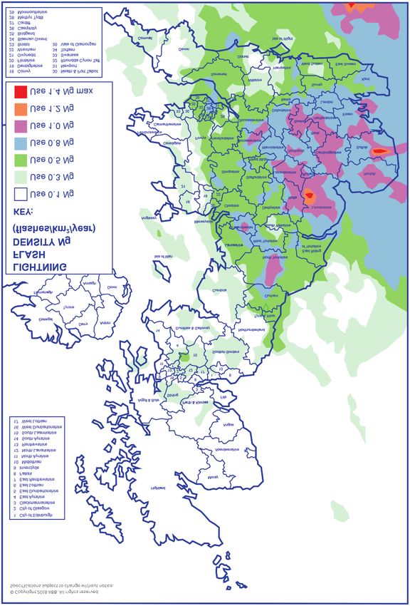
Figure 17: Voltage waveform 24 Figure 48: UK lightning flash density map 67
Figure 18: Direct Strike to Structure 24
Figure 19: Direct Strike to nearby service 25
Figure 20: Indirect Strike near Structure 25 TABLES
Figure 21: Indirect Strike near Structure 26 Table 1: Types of loss 22
Figure 22: Lightning Protection Zones concept 27 Table 2: Standardized test waveforms with peak currents
Figure 23: Lightning protection zones split by category 28 used to test SPDs at each LPZ boundary 29
Figure 24: Basic concept of SPD operation 30
Table 3: Based on 3 phase TN-S or TN-C-S
Figure 25: Simplified current division concept 33 system: 4 conductors (L1, L2, L3, N) plus
Figure 26: Current division concept for multiple services 33 Earth - 4 modes to Earth 32
Figure 27: Principle of coordinated SPDs 35 Table 4: Expected surge currents due to
Figure 28: Concept of Location Categories lightning flashes (as per BS EN 62305-1) 34
(IEEE C62.41.10) 37
Table 5: Required minimum rated impulse voltage
Figure 29: Additive effect of the inductive voltage
for a 230/240V system 36
drop to the SPD’s protection level 39
Figure 30: Influence of SPD connecting lead lengths 40 Table 6: Examples of overvoltage protection requirements 64
Figure 31: Electromagnetic field formation 41 Table 7: Calculation of fenv 65
Figure 32: Parallel or shunt installed SPD with
closely bound connecting leads to cancel magnetic
fields around the leads. 41 FLOWCHART
Figure 33: Effect of cable length on protection level 42 Flowchart 1: Overvoltage protection to Section 443 68
Figure 34: Series connected SPD 42INTRODUCTION
This publication is intended as a practical guide:
• For designers, specifiers and installers to enable them to comply with surge protection requirements in
BS 7671 Requirements for Electrical Installations – IET Wiring Regulations – 18th Edition.
• To assist those involved in the use of these standards in selecting, erecting and testing and verification of
Surge Protection Devices in accordance with BS 7671, supported by current lightning and surge
protection standards.
NOTE: BS 7671: 2018 (18th edition) applies to the design, erection and verification of electrical installations, also
additions and alterations to existing installations. Existing installations that have been installed in accordance
with earlier editions of BS 7671 may not comply with the 18th edition in every respect. This does not necessarily
mean that they are unsafe for continued use or require upgrading.
BEAMA GUIDE TO SURGE PROTECTION DEVICES (SPDs): SELECTION, APPLICATION AND THEORY 07TERMINOLOGY AND DEFINITIONS
The following common terminologies, as recognised by BS EN 61643, are used throughout SPD specifications in
order to aid correct selection and are defined as follows:
Nominal voltage U0 Is the line voltage to Earth a.c. voltage of the mains system (derived from the nominal
system voltage) for which the SPD is designed. U0 is the voltage by which the power
system is designated – e.g. 230V.
Maximum Continuous Operating Is the maximum RMS voltage that may be continuously applied to the SPD’s mode of
voltage Uc protection e.g. line to neutral mode. This is equivalent to the SPD’s rated peak voltage.
Temporary Overvoltage UT Is the stated test value of momentary voltage increase or overvoltage that the power
SPD must withstand safely for a defined time. Temporary overvoltages, typically lasting
up to several seconds, usually originate from switching operations or wiring faults (for
example, sudden load rejection, single-phase faults) as well as mains abnormalities
such as ferro-resonance effects and harmonics.
Impulse Current Iimp Is defined by three parameters, a current peak with a charge and a specific energy
typically simulated with the 10/350µs waveform to represent partial lightning currents.
This waveform is used, with peak Iimp current value stated, for the mains Type 1 SPD
Class I test and typically for data/telecom SPD Test Category D.
Nominal Discharge Current Inspd Is a defined nominal peak current value through the SPD, with an 8/20µs current
waveshape. This is used for classification of mains SPDs (Class II test) and also for
preconditioning of SPDs in Class I and Class II tests.
Maximum Discharge Current Imax Is the peak current value through the SPD, with an 8/20µs waveshape. Imax is declared
for mains Type 2 SPDs in accordance to the test sequence of the Class II operating
duty test. In general, Imax is greater than Inspd.
Combined Impulse Test with Open The test is performed using a combination wave generator where its open circuit
Circuit voltage Uoc is a hybrid voltage is defined as Uoc, typically 6kV 1.2/50µs for the mains Class III test and up to
1.2/50µs voltage test combined 4kV 1.2/50µs for signal/telecom Test Category C. With an impedance of 2 Ohm, the
with an 8/20µs current. generator also produces a peak short circuit current (sometimes referred to as Isc) at
half the value of Uoc (3kA 8/20µs for the mains Class III test and up to 2kA 8/20µs for
signal/telecom Test Category C). With both voltage and current test waveforms, the
combined impulse test is designed to stress all technologies used within SPDs.
voltage Protection Level Up Is the key parameter that characterises the performance of the SPD in limiting the
transient overvoltage across its terminals. A low protection level value (also known as
let-through voltage) is therefore particularly critical for the effective protection and
continued operation of electronic equipment. The peak voltage protection level Up is
declared when the SPD is tested with its stated nominal discharge current In (or the
peak current (Ipeak) of Iimp) and is also declared when the SPD is subject to combined
impulse test (mains Class III test for Type 3 SPDs) as well as data/telecom Test
Categories C and B.
‘Modes’ Refer to the combinations of conductors in which transient overvoltages occur.
Lightning transients are generally disturbances with respect to Earth (common mode),
whilst switching transients are disturbances between line and neutral (differential
mode). During propagation mode conversion can occur (e.g. as a result of flashover).
Hence transients can exist simultaneously between any combination of conductors.
Short-circuit current rating ISCCR Is the maximum prospective short-circuit current from the power system for which
the SPD, in conjunction with its overcurrent protective device OCPD specified, is
rated.
08 BEAMA GUIDE TO SURGE PROTECTION DEVICES (SPDs): SELECTION, APPLICATION AND THEORY1 OVERVIEW
Electronic systems now pervade almost every aspect of our lives, from the work
environment, through filling the car and even shopping at the local supermarket. As a
society, we are now heavily reliant on the continuous and efficient running of such
systems. The use of computers, electronic process controls and telecommunications has
‘increased exponentially’ during the last two decades. Not only are there more systems in
existence, the physical size of the electronics involved has reduced considerably. This
reduction in size means less energy is required to damage components.
The operation of electronic systems can be severely affected by lightning activity during ‘thunder’ storms or
electrical switching events. Both can cause very short duration increases in voltage on mains power and/or
data communication/signal/telephone lines, with potentially devastating consequences. These increases in
voltages are called surges or transient overvoltages. All sorts of electronic equipment are at risk such as
• computers
• building management systems
• PABX telephone exchanges
• CCTV equipment
• fire and burglar alarms
• uninterruptible power supplies
• programmable logic controllers (PLCs)
• plant sensors, telemetry and data acquisition equipment
• weighbridge installations
A lightning surge is severe enough to present a risk of loss of life through fire and/or electric shock hazards
through a dangerous flashover. This can occur when the surge voltage exceeds the rated impulse voltage of
the cable insulation or equipment.
The home environment has also evolved; everyday activities rely on electronic equipment. Products such as
plasma televisions, home theatre equipment, alarms, microwaves and washing machines are all vulnerable to
voltage surges. Protecting all home electronic equipment is simple with the qualified installation of a surge
protection device.
Products such as LCD screens, computer networks, data servers and industrial equipment including PLCs
provide essential services now crucial to business operational productivity. Protection against the effects of
voltage surges in business today is no longer an option, it has become a necessity.
Circuit breakers/fuses are not designed to provide overvoltage protection
Fuses and circuit breakers (aka Overcurrent Protective Devices (OCPDs) are designed to protect your home,
business, equipment, and possibly even your life from an event such as a short circuit or overload.
The Surge Protective Device (hereafter referred to as an SPD) is specifically designed to protect equipment
from events such as extremely short duration high voltage spikes. These voltage spikes or transients are
everyday occurrences, and can be caused by anything from switching on a lamp to a lightning storm. Most
spikes are of low energy. Some spikes could possibly cause irreparable damage to equipment if no SPD is
installed to redirect the harmful voltage away from the equipment.
BEAMA GUIDE TO SURGE PROTECTION DEVICES (SPDs): SELECTION, APPLICATION AND THEORY 091.1 SURGE PROTECTION DEVICES (SPDs)
A Surge Protection Device (SPDs) is a component of the electrical installation protection system. This device is
connected to the power supply in parallel with the loads (circuits) that it is intended to protect (see Fig. 1). It
can also be used at all levels of the power supply network. This is the most commonly used and most practical
type of overvoltage protection.
Principle of Surge Protection Operation
SPDs are designed to limit transient overvoltages due to lightning or switching and divert the associated surge
currents to earth, so as to limit these overvoltages to levels that are unlikely to damage the electrical
installation or equipment.
X Incoming
Circuit Breaker
X X X
S
Lightning P
D X X X X X
Current
Sensitive Loads
FIGURE 1 – PRINCIPLE OF PROTECTION SySTEM IN PARALLEL
1.2 TYPES OF SURGE PROTECTION DEVICES
There are three types of SPD according to international standards:
• Type 1 SPD – Protection Against Transient Overvoltages due to Direct Lightning Strokes
The Type 1 SPD is recommended to protect electrical installations against partial lightning currents
caused by direct lightning strokes. It can discharge the voltage from lightning spreading from the earth
conductor to the network conductors.
Type 1 SPD is characterised by a 10/350µs current wave.
• Type 2 SPD – Protection Against Transient Overvoltages due to Switching and Indirect
Lightning Strokes
The Type 2 SPD is the main protection system for all low voltage electrical installations. Installed in each
electrical switchboard, it prevents the spread of overvoltages in the electrical installations and protects
the loads.
10 BEAMA GUIDE TO SURGE PROTECTION DEVICES SPDs): SELECTION, APPLICATION AND THEORYType 2 SPD is characterised by an 8/20µs current wave.
• Type 3 SPD – Local Protection for Sensitive Loads
These SPDs have a low discharge capacity. They must therefore only be installed as a
supplement to Type 2 SPD and in the vicinity of sensitive loads. They are widely available as hard wired’
devices (frequently combined with Type 2 SPDs for use in fixed installations) However they are also
incorporated in
SURGE PROTECTED
SURGE PROTECTED TELECOMS AND DATA
PORTABLE SOCKET
SOCKET OUTLETS PROTECTION
OUTLETS
2A TYPE 1 2B TYPE 2
2C TYPE 3
Note 1 : – Combinations of SPD types are available as a single unit.
1.3 REQUIREMENTS WITHIN THE WIRING REGULATIONS
The IET Wiring Regulations (BS 7671 – Requirements for Electrical Installations) define the requirements for a safe
electrical installation. Part of the criteria is adequate protection for both people and equipment from transient over
voltages of atmospheric origin transmitted via the supply distribution system and against switching overvoltages.
Two specific sections which relate to SPDs are:
• Section 443 – Protection against transient overvoltages of atmospheric origin or due to switching
(See Annex B of this Guide for details)
• Section 534 – Devices for protection against overvoltage. This section covers the selection and erection of
SPDs for protection against transient overvoltages where required by Section 443.
BEAMA GUIDE TO SURGE PROTECTION DEVICES (SPDs): SELECTION, APPLICATION AND THEORY 112 TRANSIENT OVERVOLTAGES (SURGES)
2.1 WHAT ARE TRANSIENT OVERVOLTAGES (SURGES)?
A transient overvoltage or surge is a short duration increase in voltage measured between two or more
conductors.
In this context short means anything from microseconds (millionths of a second) to a few milliseconds
(thousandths of a second) in duration.
The increase in voltage will vary from a few volts to thousands of volts.
This voltage exists between two or more conductors. For a mains power supply, these conductors would be
the line, neutral and earth. For data, telecom and signal lines, these conductors would be line(s) and
earth/screen.
FIGURE 2 – TRANSIENT OVERVOLTAGES (SURGES)
‘Transient overvoltage’, is technically and descriptively the best terminology. However, transients are also
referred to as surges, spikes and glitches. The term ‘surge’, though widely used, should be used with caution.
In some parts of the world, the UK amongst them, surge is used by the electricity supply industry to refer to a
sustained overvoltage of several cycles duration.
2.2 OTHER TYPES OF ELECTRICAL DISTURBANCE
Transient overvoltages are by definition a very specific form of disturbance. It is therefore worth briefly
outlining other forms of electrical disturbance in order to understand what transient overvoltages are not!
Most of these disturbances can be represented as a serious deviation of the normal mains power supply as
shown by Figure 3 below.
FIGURE 3 – NORMAL MAINS SUPPLy WAVEFORM
12 BEAMA GUIDE TO SURGE PROTECTION DEVICES (SPDs): SELECTION, APPLICATION AND THEORY2.2.1 ‘Outage’
‘Outage’, ‘power cut’ and ‘blackout’ are all terms applied to total breaks in the supply lasting from
several milliseconds to many hours. Very short breaks, which cause lights to flicker, may be
sufficient to cause computers and other sensitive electronic equipment. to ‘crash’
FIGURE 4 – OUTAGE
2.2.2 Undervoltages
‘Undervoltages’ or ‘brownouts’ are sustained reductions in the supply voltage, lasting anything
over a few seconds.
FIGURE 5 – UNDERVOLTAGES
2.2.3 Overvoltages
‘Overvoltages’ are sustained increases in the supply voltage, lasting anything over a few seconds.
FIGURE 6 – OVERVOLTAGES
BEAMA GUIDE TO SURGE PROTECTION DEVICES (SPDs): SELECTION, APPLICATION AND THEORY 132.2.4 ‘Sags’
Sags’ or ‘dips’ are decreases in the supply voltage, lasting no more than a few seconds.
FIGURE 7 – ‘SAGS’
2.2.5 ‘Swells’
‘Swells’ (also called ‘surges’) are increases in the supply voltage, lasting no more than a few
seconds.
FIGURE 8 – ‘SWELLS’
2.2.6 Radio Frequency Interference
Electrical noise or Radio Frequency Interference (RFI), is a continuous high frequency (5kHz or
more) distortion of the normal sine wave.
FIGURE 9 – RADIO FREqUENCy INTERFERENCE
14 BEAMA GUIDE TO SURGE PROTECTION DEVICES (SPDs): SELECTION, APPLICATION AND THEORY2.2.7 Harmonics
Harmonics are a continuous distortion of the normal sine wave, at frequencies of up to 3kHz.
FIGURE 10 – HARMONICS
2.2.8 NEMP/EMP
Nuclear ElectroMagnetic Pulse (NEMP), or ElectroMagnetic Pulse (EMP), are pulses of energy
caused by nuclear explosions and intense solar activity. NEMP or EMP transients are much quicker
(as faster rise time) than commonly occurring transients.
FIGURE 11 – NEMP/EMP
2.2.9 Electrostatic Discharge
ElectroStatic Discharge (ESD) is a different phenomenon. Unlike the above these do not tend to
be transmitted on power or data lines. An electrostatic charge is generated by two insulating
objects being rubbed together. A charged object will discharge when it comes into contact with a
conducting object. A common example of the charging mechanism could be someone walking
over a synthetic carpet. The discharge would occur when the electrically charged person touches
a door handle or computer keyboard.
2.2.10 Electromagneic Interference
ElectroMagnetic Interference (EMI) is a very broad term referring to system interference.
ElectroMagnetic Compatibility (EMC) is a philosophy referring to attempts to prevent EMI. EMC
practice dictates that potential sources of interference are designed so as not to affect
equipment, and that potential victim equipment is designed to be immune from potential source
of interference. Lightning cannot be prevented at source, and cannot be fully protected against
with EMC.
BEAMA GUIDE TO SURGE PROTECTION DEVICES (SPDs): SELECTION, APPLICATION AND THEORY 153 TRANSIENT OVERVOLTAGE DAMAGE
Transient overvoltages are generally caused by lightning and/or electrical switching events. Transient
overvoltages can be generated by lightning, (through resistive, inductive or capacitive coupling) or by
electrical switching events. About 35% of all transients come from outside the facility from such sources as
lightning, utility grid switching, switching large capacitor banks on the utility lines, electrical accidents or
heavy motors or loads from nearby industry. The remaining 65% are generated inside our homes and
facilities and come from such unsuspected sources as microwave ovens, laser printers and copiers,
electric motors, electrical appliances and even lights being switched on or off.
3.1 BY LIGHTNING
Lightning activity can cause transient overvoltages on both mains power supplies and data
communication, signal or telephone lines.
Lightning discharges are claimed to have currents of up to half a million amperes (A), although 200 kA is an
accepted upper limit within present standards for lightning protection. Were lightning to hit a building
without a structural lightning protection scheme, this current would seek a path to earth through the
building and its fabric – in an erratic and unpredictable manner. The building is likely to be damaged and
may even catch fire. Although transient overvoltages will occur, this may be just one aspect of extensive
damage to the building and its contents.
If however, lightning strikes a building with structural lightning protection the lightning will travel to earth
in a predetermined manner.
Lightning can cause transient overvoltages through
• direct strikes to incoming electrical services
• ‘indirect’ strikes, which are coupled into electrical services through resistive, inductive and
capacitive effects.
3.1.1. Direct strikes
Direct strikes to High voltage (Hv) power cables. Strikes to HV overhead power lines are quite common.
It is often thought that the high voltage to low voltage transformer action eliminates the resultant transient
overvoltages. This is not so. Although transformers protect against transient overvoltages between line and
earth, line to line transients pass through unattenuated.
When HV lines are struck by lightning they flashover to earth. One line will flashover before the others,
converting a line to earth transient into one between line and line – these will easily pass through the
transformer.
Also, capacitance between the transformer’s windings provides transients between any combination of
conductors with a high frequency path through the transformer. This could have the effect of increasing
the size of existing line to line transients, as well as providing a path through the transformer for line to
earth transients.
Direct strikes to Low voltage (Lv) power cables or telephone lines. When lightning hits LV overhead
power cables or telephone lines, most of the current travels to earth as a result of line flashover to ground.
A relatively small (but devastating) portion of the lightning current is transmitted along the cable or line to
electronic equipment.
16 BEAMA GUIDE TO SURGE PROTECTION DEVICES (SPDs): SELECTION, APPLICATION AND THEORY3.1.2 Indirect strikes
3.1.2.1 Resistive coupling
Resistive coupling is the most common cause of transient overvoltages and it will affect both
underground and overhead lines. Resistively coupled transients occur when a lightning strike raises the
electrical potential of one or more of a group of electrically interconnected buildings (or structures).
Common examples of electrical interconnections are
• power feeds from substation to building
• building to building power feeds
• power supplies from the building to external lightning, CCTV or security equipment
• telephone lines from the exchange to the building
• between building telephone lines
• between building LANs or data communication lines
• signal or power lines from a building to external or field based sensors
Figure 12 shows two buildings. Each contains electronic equipment which is connected to Earth through
its mains power supply. A data communication line connects the two pieces of equipment and hence the
two separate Earths.
FIGURE 12 – POTENTIAL CURRENT PATH IN BUILDINGS CONNECTED THROUGH DATA COMMUNICATION LINES
A nearby lightning strike will inject a massive current into the ground. The current flows away from the
strike point – preferentially through the path of least resistance. The earth electrode, electrical cables and
the circuitry of the electronic equipment (once damaged), are all better conductors than soil. As the
current attempts to flow, devastating transient overvoltages are present across the sensitive components
of the equipment.
Resistively coupled transients can occur when separately earthed structures are only metres apart.
Resistive coupling will affect both underground and overhead cables.
Note: SPDs for data communication signal and telephone lines (‘Lightning Barriers’) are fitted into the line (i.e. in series).
This introduces a small impedance into the line and a capacitance across the line. For twisted pair signalling below 1
MHz, this generally causes no problems. However, at higher frequencies this impedance and capacitance would cause
problems. Protectors for these systems need to be specially designed to have lower line capacitance and impedance.
For impedance matched systems (e.g. coaxially wired computer networks such as Ethernet) it is essential that the
protector is impedance matched, in order to avoid reflections.
BEAMA GUIDE TO SURGE PROTECTION DEVICES (SPDs): SELECTION, APPLICATION AND THEORY 173.1.2.2 Inductive coupling
Inductive coupling is a magnetic field transformer effect between lightning and cables.
A lightning discharge is an enormous current flow and whenever a current flows, an electromagnetic field
is created around it. If power or data cabling passes through this magnetic field, then a voltage will be
picked up by, or induced onto it.
FIGURE 13 – INDUCTIVE COUPLING
3.1.2.3 Capacitive coupling
Where long lines are well isolated from earth (e.g. via transformers or opto-isolators) they can be pulled up
to high voltages by capacitance between them and charged thunder clouds. If the voltage on the line rises
beyond the breakdown strength of the devices at each end (e.g. the opto-isolators) they will be damaged.
3.2 BY ELECTRICAL SWITCHING EVENTS
Transient overvoltages caused by electrical switching events are very common and can be a source of
considerable interference. Current flowing through a conductor creates a magnetic field in which energy
is stored. When the current is interrupted or switched off, the energy in the magnetic field is suddenly
released. In an attempt to dissipate itself it becomes a high voltage transient. The more stored energy, the
larger the resulting transient. Higher currents and longer lengths of conductor, both contribute to more
energy stored and subsequently released. This is why inductive loads such as motors, transformers and
electrical drives are all common causes of switching transients
3.3 BY TRANSIENT OVERVOLTAGE
Nearly all electronic components and circuits suffer transient overvoltages damage in the same way.
There are two main physical mechanisms at work, overheating and insulation failure – both are made
much worse by the subsequent power follow-on.
Let us consider a simple resistor made from a coil of resistance wire. During transient activity the current
flowing through the wire, will cause degradation to occur. A little more heat and the wire will vaporize –
destroying the component. Heat failure, such as this, is common in fuses, printed circuit board tracks,
forward biased semiconductor junctions and the like.
In addition to heating, the current flow causes a voltage to be generated across the wire. If the voltage
difference becomes high enough to pierce the wire insulation and breakdown the air gap, flashover
occurs. This form of failure is common with reverse biased semiconductor junctions, capacitors,
transformers, motor windings and such like.
18 BEAMA GUIDE TO SURGE PROTECTION DEVICES (SPDs): SELECTION, APPLICATION AND THEORYFor example, consider a transformer winding and an earthed lamination. If a small transient voltage is
present between the winding and earth, no current flows and no heating occurs. However, if a larger
transient voltage is present, flashover or insulation breakdown occurs, and a transient current flows
through the transformer, causing heating, burning and arcing. In a minor case the transformer would be
able to continue operation after the event. The next transient would find it much easier to flashover the
now degraded insulation. The process could then continue until a catastrophic short circuit failure occurs.
In severe cases the first transient will be terminal!
When components connected across power supplies fail, the majority of the physical damage (charring,
burning or explosion) is the result of the follow-on current. This occurs when the power current flows
down the damage path created by the transient overvoltage.
It should be noted that integrated circuits are collections of components and inter-connections. Their
inter-connections behave like PCB tracks and its components include forward biased or reverse biased
junctions, resistors and capacitors.
A third form of failure is not due to a physical mechanism, but the incorrect operation of systems caused
by transients. In power supplies and power conversion equipment, two semiconductor devices are often
connected in series across a supply to form the arm of the bridge. The two devices must never be on
simultaneously. However, transient overvoltages can cause them to trigger at the wrong time, short
circuiting the supply, with devastating consequences.
3.4 THE PROBLEMS CAUSED BY TRANSIENT OVERVOLTAGES
Transient overvoltages, whether caused by lightning or by electrical switching, have similar effects:
disruption, degradation, damage and downtime.
3.4.1 Disruption
Although no physical damage is caused, the logic or analogue levels of the systems are upset, causing
• data loss
• data and software corruption
• unexplained computer crashes
• lock-ups
• the unwanted tripping of Residual Current Devices (RCDs)
The system can be reset (often just by switching off and on) and will then function normally. Much of this
nuisance may go unreported.
3.4.2 Degradation
This is somewhat more serious. Long term exposure to lower level transient overvoltages will, unknown to
the user, degrade electronic components and circuitry reducing the equipment’s expected life and
increasing the likelihood of failures.
TRANSIENT OVERVOLTAGES, WHETHER
CAUSED BY LIGHTNING OR BY ELECTRICAL
SWITCHING, HAVE SIMILAR EFFECTS:
DISRUPTION, DEGRADATION, DAMAGE
AND DOWNTIME
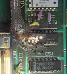
BEAMA GUIDE TO SURGE PROTECTION DEVICES (SPDs): SELECTION, APPLICATION AND THEORY 193.4.3 Damage
Large transient overvoltages can cause damage to components, circuit boards
and I/O cards. Severe transient overvoltages can physically manifest themselves
through burnt-out circuit boards, however, ordinarily damage is less spectacular
(see Fig 14). Similar degradation can occur to the silicon dioxide insulation in
integrated circuits (or microchips). Only in most severe cases do we see ruptured
cases, charring and fire. In fact much of this more spectacular damage is caused
by power follow-on and not by the transient.
When a transient overvoltage causes a short circuit failure, this can create a path
for the power supply. Consider a component connected to line and neutral on a
mains power supply, failing under short-circuit conditions as a result of a
transient. At this point no outward signs of damage exist. Current flows into the
FIGURE 14 – DAMAGE short circuit and continues until a protective device operates or the component
fails, sometime spectacularly. This also explains why it is often difficult to tell how
big a transient overvoltage was by looking at the damage it caused.
3.4.4 Downtime
Unnecessary disruption, component degradation and damage all result in equipment and systems downtime,
which means
• staff unable to work
• staff overtime
• senior managers and technical specialists unnecessarily tied-up problem solving
• lost data which may result in
• lost productivity
• delays to customers
• lost business
Example 1 – Switching transients
An engineering company invested heavily in a networked Computer Aided Design (CAD) system. However,
the system’s many advantages were overshadowed by the all too regular problems it suffered. The system
would crash unexpectedly, sometimes hours or work were lost or corrupted and circuit failures seemed to be
almost a monthly event. At first, these were assumed to be just ‘teething troubles’. But as time went on, and
design work slipped further behind schedule, relations with the system’s supplier became increasingly
difficult. Only when one of the engineering team read an article in a professional journal, did they realise that
the problem might not be the system, but the environment. They soon observed that the system’s failures
coincided with the operation of a large drawing copying machine. The operation of this equipment lead to
switching transients appearing on the mains supply to the CAD system.
Example 2 – Lightning strike to research centre
A lightning strike to a research campus had widespread effects. The PBX telephone exchange was rendered
almost totally inoperable, with 80% of the external telephone lines taken out of commission. The pattern of
damage clearly indicated induced transient overvoltages on the incoming telephone lines. Elsewhere, there
was extensive damage to computer equipment in the admin block, which was closest to the strike point. This
equipment was networked to equipment in neighbouring buildings where transceivers, repeaters and some
terminals were damaged – indicative of resistively coupled transient overvoltages.
Example 3 – Lightning strike to office block
When lightning struck an office block, its structural lightning protection ensured that the lightning current
was carried safely to earth – without damage to the building or its occupants. However, sizeable transient
overvoltages were induced on to the mains power supply within the building. Costly damage was suffered to
the building management system, its UPS, the door entry system, the telephone exchange, and a large
number of computer terminals. Over subsequent months, there were a number of failures to pieces of
equipment apparently undamaged during the initial incident – suggesting component degradation had
occurred.
20 BEAMA GUIDE TO SURGE PROTECTION DEVICES (SPDs): SELECTION, APPLICATION AND THEORY4 BS EN 62305 PROTECTION
AGAINST LIGHTNING
The BS EN 62305 standard series specifically cover the protection against lightning to structures, their
contents, persons and livestock.
BS EN 62305 accepts that we now live in the electronic age, making LEMP (Lightning Electromagnetic
Impulse) protection for electronic and electrical systems an integral part of the standard through
BS EN 62305-4. LEMP is the term given to the overall electromagnetic effects of lightning, including
conducted surges (transient overvoltages and currents) and radiated electromagnetic field effects.
Our reliance as a society on electronic equipment has increased dramatically over the last two decades;
hence BS EN 62305 has specifically recognised the protection of such equipment within a normative part
BS EN 62305-4 which states:
“Lightning as a source of harm is a very high-energy phenomenon. Lightning flashes release many
hundreds of mega-joules of energy. When compared to the milli-joules of energy that may be
sufficient to cause damage to sensitive electronic equipment in electrical and electronic systems
within a structure, it is clear that additional protection measures will be necessary to protect some of
this equipment.
“The need for this International Standard has arisen due to the increasing costs of failures of electrical
and electronic systems, caused by electromagnetic effects of lightning. Of particular importance are
electronic systems used in data processing and storage as well as process control and safety for plans
of considerable capital cost, size and complexity (for which plant outages are very undesirable for cost
and safety reasons).”
BS EN 62305 – 4 categorises the source of damage, type of damage and the type of loss
4.1 SOURCES OF DAMAGE
Damage that can be caused by lightning is sub-divided into:
• Damage to a structure (including all incoming electrical overhead and buried lines
connected to the structure)
• Damage to a service (service in this instance being part of telecommunication, data,
electrical supply, water, gas and fuel distribution networks).
S1 Flashes to
the structure
S3 Flashes to the services
connected to the structure
Overhead service connected
to the structure eg Telephone
Structure
S2 Flashes near to
the structure
S4 Flashes near to the services
connected to the structure
Ground level
Underground service connected to the
structure eg Low voltage mains supply
FIGURE 15 – DIFFERENT AREAS OF LIGHTNING STRIKE
BEAMA GUIDE TO SURGE PROTECTION DEVICES (SPDs): SELECTION, APPLICATION AND THEORY 214.2 TYPES OF DAMAGE
Each source of damage may result in one or more of three types of damage. The possible types of
damage are identified as follows:
D1 Injury of persons or livestock due to step and touch voltages
D2 Physical damage (fire, explosion, mechanical destruction, chemical release) due to lightning
current effects including sparking
D3 Failure of internal systems due to Lightning Electromagnetic Impulse (LEMP)
This wider approach of taking into account the specific services (power, telecom and other lines) that are
connected to the structure identifies that fire and or an explosion could occur as a result of a lightning
strike to or near a connected service (these being triggered by sparks due to overvoltages and partial
lightning currents that are transmitted via these connected services). This in turn could have a direct
bearing on the specific types of loss.
4.3 TYPES OF LOSS
The following types of loss may result from damage due to lightning;
L1 Loss of human life
L2 Loss of service to the public
L3 Loss of cultural heritage
L4 Loss of economic value
NOTE: L4 relates to the structure and its contents; to the service and the loss of activity, due to the loss. Typically, loss of expensive and
critical equipment that may be irretrievably damaged due to the loss of the power supply or data/telecom line Similarly the loss of vital
financial information for example, that could not be passed onto clients of a financial institution due to damage, degradation or
disruption of internal IT hardware caused by lightning transients.
The relationships of all of the above parameters are summarised in Table 1.
Point of strike Source of Type of Type of
damage damage loss
Structure S1 D1 L1, L4**
D2 L1, L2, L3, L4
D3 L1*, L2, L4
Near a S2
Structure D3 L1*, L2, L4
Service connected S3 D1 L1,L4**
to the structure D2 L1, L2, L3, L4
D3 L1*, L2, L4
Near a service S4 D3 L1*, L2, L4
TABLE 1 – TyPES OF LOSS
* Only for structures with risk of explosion and for hospitals or other structures where failures of internal
systems immediately endangers human life.
** Only for properties where animals may be lost.
22 BEAMA GUIDE TO SURGE PROTECTION DEVICES (SPDs): SELECTION, APPLICATION AND THEORYLEMP damage is so prevalent that it is identified as one of the specific types (D3) against which protection
should be provided and can occur from ALL strike points to the structure or connected services – direct or
indirect. This extended approach also takes into account the danger of fire or explosion associated with
services connected to the structure, e.g. power, telecoms and other metallic lines.
BS EN 62305-4 is an integral part of the complete standard. By integral we mean that following a risk
assessment as detailed in BS EN 62305-2, the structure in question may need both a structural lightning
protection system (LPS) and a fully coordinated set of SPDs to bring the risk below the accepted tolerable
levels defined within the standard. BS EN 62305 makes it clear that structural lightning protection must no
longer be considered in isolation from transient overvoltage/surge protection and given that lightning
from all strikes points, direct or indirect, to the structure or connected services creates a risk from
transients, SPDs are a vital means of protection whether structural lightning protection is present or not.
4.4 CHARACTERISING TRANSIENT CURRENTS AND VOLTAGES
4.4.1 Current and voltage waveforms
BS EN 62305 takes account of protection measures on metallic service lines (typically power, signal and
telecom lines) using transient overvoltage or Surge Protection Devices (SPDs) against both direct lightning
strikes as well as the more common indirect lightning strikes and switching transients. Standards such as
the BS EN 61643 series define the characteristics of lightning currents and voltages to enable reliable and
repeatable testing of SPDs (as well as lightning protection components). Although these waveforms may
differ from actual transients, the standardized forms are based upon years of observation and
measurement (and in some cases simulation). In general they provide a fair approximation of the real
world transient.
Transient waveforms have a fast rising edge and a longer tail. They are described through their peak value
(or magnitude), rise time and their duration (or fall time). The duration is measured as the time taken for
the test transient to decay to half its peak value.
The figures below illustrate the common current and voltage waveforms that are used to test SPDs for
mains, signal and telecom lines.
30
Imax at t = 8µs
Iimp at t = 10µs
Surge Current (kA)
20
10/350µs Waveform
10 Imax at t = 20µs Iimp at t = 350µs
2 2
8/20µs Waveform
200 400 600 800 1000
Time t (µs)
FIGURE 16 – CURRENT WAVEFORM
BEAMA GUIDE TO SURGE PROTECTION DEVICES (SPDs): SELECTION, APPLICATION AND THEORY 23Vpeak at t = 1.2µs
Vpeak at t = 10µs
4
10/700µs Waveform
3
Surge Current (kA)
2 Ipeak at t = 50µs Iimp at t = 700µs
2 2
1
1.2/50µs Waveform
300 600 900 1200 1500
Time t (µs)
FIGURE 17 – VOLTAGE WAVEFORM
4.4.2 Sources of damage
Lightning currents as a result of direct lightning strikes are represented by the simulated 10/350µs
waveform with a fast rise time and long decay that replicates the high energy content of direct lightning.
4.4.2.1 Direct strikes
Direct lightning can inject partial lightning currents of the 10/350µs waveform into a system where a
structure with a structural Lightning Protection System receives a direct strike (Source S1) or where
lightning directly strikes an overhead service line (Source S3).
Structural LPS
10/350µs
surge current
(Iimp)
Damped current
waveshape (8/20µs)
Ground Level
FIGURE 18 – DIRECT STRIKE TO STRUCTURE
24 BEAMA GUIDE TO SURGE PROTECTION DEVICES (SPDs): SELECTION, APPLICATION AND THEORY10/350µs
surge current
(Iimp)
(Iimp)/2
(Iimp)/2
Ground Level
FIGURE 19 – DIRECT STRIKE TO NEARBy SERVICE
4.4.2.2 Indirect strikes
Remote or indirect lightning flashes near the structure (Source S2) or near a connected service to the
structure (Source S4) of up to 1km radius away (and hence far more common) are represented by the
8/20µs waveform. Induced surges from direct lightning flashes and switching sources are also represented
by this waveform. With a much shorter decay or fall time relative to the 10/350µs waveform, the 8/20µs
waveform presents significantly less energy (for an equivalent peak current) but is still devastating enough
to damage electrical and electronic equipment.
8/20µs
surge current Ground Level
FIGURE 20 – INDIRECT STRIKE NEAR STRUCTURE
BEAMA GUIDE TO SURGE PROTECTION DEVICES (SPDs): SELECTION, APPLICATION AND THEORY 25Strike up to
1km away
Induced Surges/
Overvoltages
8/20µs
surge current
8/20µs
surge
Ground Level current
FIGURE 21 – INDIRECT STRIKE NEAR STRUCTURE
BS EN 62305-1 recognises that failure of internal systems (Damage Type D3) due to Lightning
Electromagnetic Impulse (LEMP) is possible from all points of strike to the structure or service – direct or
indirect (all Sources: S1, S2, S3 and S4).
4.5 SURGE PROTECTION MEASURES (SPM)
Surge Protection Measures (SPM) were previously known as LEMP Protection Measures Systems (LPMS) in
BS EN 62305.
There are several techniques, which can be used to minimise the lightning threat to electronic systems.
Like all security measures, they should wherever possible be viewed as cumulative and not as a list of
alternatives. BS EN 62305 defines this as a complete system of protection measures for internal systems
against LEMP with the term Surge Protection Measures (SPM).
BS EN 62305-4 describes a number of measures to minimise the severity of transient overvoltages caused
by lightning and electrical switching.
Key and basic protection measures are
• Earthing and bonding
• Electromagnetic shielding and line routing
• Coordinated Surge Protective Devices
Further additional protection measures include:
• Extensions to the structural LPS
• Equipment location
• Use of fibre optic cables (protection by isolation)
Note: For the purpose of this guide and its scope, protection measures utilising SPDs will only be considered. See BS EN
62305 for further details of all protection measures.
SPMs also have to operate within and withstand the environment in which they are located considering
factors such as temperature, humidity, vibration, voltage and current.
26 BEAMA GUIDE TO SURGE PROTECTION DEVICES (SPDs): SELECTION, APPLICATION AND THEORYSelection of the most suitable SPM is made using the risk assessment in accordance with BS EN 62305-2
taking into account both technical and economic factors. For example, it may not be practical or cost
effective to implement electromagnetic shielding measures in an existing structure so the use of
coordinated SPDs may be more suitable. Ideally SPDs are best incorporated at the project design stage,
although they can also be readily installed in existing installations.
To ensure continuous operation of critical systems even in the event of a direct strike, SPDs are essential
and these must be suitably deployed, based on the source of surge and its intensity using the Lightning
Protection Zones (LPZ) concept within BS EN 62305-4.
4.5.1 The Lightning Protection Zone (LPZ) concept
Protection against LEMP is based on a concept of the Lightning Protection Zone (LPZ) that divides the
structure in question into a number of zones according to the level of threat posed by the LEMP. The
general idea is to identify or create zones within the structure where there is less exposure to some or all
of the effects of lightning and to coordinate these with the immunity characteristics of the electrical or
electronic equipment installed within the zone. Successive zones are characterised by significant
reductions in LEMP severity as a result of bonding, shielding or the use of SPDs.
Figure 22 illustrates the basic LPZ concept defined by protection measures against LEMP as detailed in
BS EN 62305-4. Here equipment is protected against lightning, both direct and indirect strikes to the
structure and services, with an SPM. This comprises spatial shields, bonding of incoming metallic services,
such as water and gas, and the use of coordinated SPDs.
A spatial shield is the terminology used to describe an effective screen against the penetration of LEMP. An
external LPS or conductive reinforcing bars within the structure or room would constitute spatial shields.
Cable for data
transmission system
LPZ 0
Low voltage
electrical
supply cable Mast or
Boundary railing
SPD at LPZ 0/1 for lightning current protection
of LPZ 2** B
SPD at LPZ 1/2 for overvoltage protection
LPZ 2 B Extraneous-conductive-part connected to
main earthing terminal
Boundary
of LPZ 1* * Boundary of LPZ 1 is an external Lightning
Equipment Critical Protection System (LPS)
equipment * Boundary of LPZ 2 is a screened room to reduce
the effects of electromagnetic interference (EMI)
B Equipment
LPZ 1
Metallic Telecommunications
B cable
water pipe
Metallic gas pipe
FIGURE 22 – LIGHTNING PROTECTION ZONES CONCEPT
BEAMA GUIDE TO SURGE PROTECTION DEVICES (SPDs): SELECTION, APPLICATION AND THEORY 27The LPZs can be split into two categories (see Figure 23 below) – 2 external zones (LPZ 0A, LPZ 0B) and
usually 2 internal zones (LPZ 1, 2) although further zones can be introduced for a further reduction of the
electromagnetic field and lightning current if required.
LPZ 0A S1 Flash to the
structure
S3 Flash to a service
connected to
the structure
LPZ 0B
Equipotential SPD 0B/1 Safety distance
bonding by against too high
means of SPD a magnetic field
SPD 0A/1
LPZ 1 ds
Rolling sphere Rolling sphere
radius radius
S4 Flash near a service S S2 Flash near
connected to
P
D
1/2 to the
the structure S LPZ 2 structure
P
D
1/2
LPZ 0B LPZ 0B
Ground level
SPD 0A/1
LPZ OA Direct flash, full lightning current, full magnetic field
LPZ OB No direct flash, but partial lightning or induced current, full magnetic field
LPZ 1 No direct flash, but partial lightning or induced current, damped magnetic field
LPZ 2 No direct flash, or partial lightning, but induced currents, further damped magnetic field
Protected volumes inside LPZ 1 and LPZ 2 must respect safety distances ds
FIGURE 23 – LIGHTNING PROTECTION ZONES SPLIT By CATEGORy
External zones:
• LPZ 0A is the area subject to direct lightning strikes and therefore may have to carry up to the full
lightning current. This is typically the roof area of a structure without structural lightning protection.
The full electromagnetic field occurs here.
• LPZ 0B is the area not subject to direct lightning strikes and is typically the sidewalls of a structure
or a roof with structural lightning protection. However the full electromagnetic field still occurs
here and conducted partial or induced lightning currents and switching surges can occur here.
Internal zones:
• LPZ 1 is the internal area that is subject to partial lightning currents. The conducted lightning
currents and/or switching surges are reduced compared with the external zones LPZ 0A, LPZ 0B as
is the electromagnetic field if suitable shielding measures are employed. This is typically the area
where services enter the structure or where the main power switchboard is located.
• LPZ 2 is an internal area that is further located inside the structure where the remnants of lightning
impulse currents and/or switching surges are reduced compared with LPZ 1. Similarly the
electromagnetic field is further reduced if suitable shielding measures are employed. This is
typically a screened room or, for mains power at the sub-distribution board area.
The general concept of zoning is not new. It was part of Annex C of BS 6651 “Protection of structures
against lightning” and was defined by three distinct location categories with differing surge exposure levels,
(Category A, B and C).These 3 location categories are still recognised within IEEE C62.41.1 standard series.
Note: BS 6651 has been superseded by BS EN 62305 and subsequently withdrawn.
28 BEAMA GUIDE TO SURGE PROTECTION DEVICES (SPDs): SELECTION, APPLICATION AND THEORY4.7 SPD TEST PARAMETERS, TYPES, LOCATION AND APPLICATION
Given that the live cores of metallic electrical services such as mains power, data and telecom cables
cannot be bonded directly to earth wherever a line penetrates each LPZ, a suitable SPD is therefore
needed. The SPD’s characteristics at the boundary of each given zone or installation location need to take
account of the surge energy they are likely to be subject to as well as ensure the transient overvoltages are
limited to safe levels for equipment within the respective zone.
The following table details the standardized test waveforms with peak currents used to test SPDs typically
located at each zone boundary.
LPZ 0/1 LPZ 1 /2 LPZ 2/3
Typical SPD Service Entrance Sub-distribution Terminal Equipment
Installation point (e.g. Main distribution board or telecom (e.g. socket outlet)
board or telecom NTP) PBX frame
Mains Test
VI IV2 IIV3
Class/SPD Type ( 1)
Surge test waveform 10/350 current 8/20 current Combination 8/20 current
and 1.2/50 voltage
Typical peak test 25kA (2) 40kA 3kA (with 6kV)
current (per mode)
Signal/Telecom D1 (3) C2 (3) C1 1. Tests to BS EN 61643 series
Test Category ( 1) 2. Peak current (per mode) for
a phase SPD to protect a
Surge test waveform 10/350 current Combination 8/20 Combination 8/20
current and 1.2/50 current and 1.2/50 TNS mains system
voltage voltage 3. Test category B2 10/700
2.5kA voltage waveform (also within
Typical peak test 2kA (with 4kV) 0.5kA (with1kV)
ITU-T standards) up to 4kV
current (per mode)
peak also permissible
TABLE 2 – STANDARDIZED TEST WAVEFORMS WITH PEAK CURRENTS USED TO TEST SPDs AT EACH LPZ BOUNDARy
BEAMA GUIDE TO SURGE PROTECTION DEVICES (SPDs): SELECTION, APPLICATION AND THEORY 29You can also read