Shaping concrete An investigation of knitted formwork for concrete casting
←
→
Page content transcription
If your browser does not render page correctly, please read the page content below
Shaping concrete
An investigation of knitted formwork for concrete casting

Master’s thesis in Master’s Program Structural Engineering and Building Technology

VERA SEHLSTEDT

Department of Architecture and Civil Engineering
Research Group for Architecture and Engineering
CHALMERS UNIVERSITY OF TECHNOLOGY
Master’s Thesis ACEX30
Gothenburg, Sweden 2021
Master’s thesis ACEX30

                               Shaping concrete

                An investigation of knitted formwork for concrete casting

Master’s Thesis in the Master’s Programme Structural Engineering and Building Technology

                                   VERA SEHLSTEDT

                     Department of Architecture and Civil Engineering
                     Research Group for Architecture and Engineering
                    CHALMERS UNIVERSITY OF TECHNOLOGY
                               Gothenburg, Sweden 2021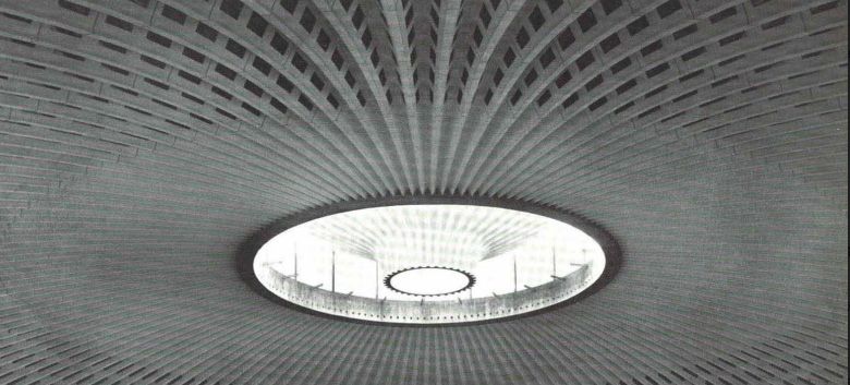
Forma betong

                   Utforskning av stickade gjutformar för betong

Master’s Thesis in the Master’s Programme Structural Engineering and Building Technology
VERA SEHLSTEDT

  VERA SEHLSTEDT, 2021

Examensarbete ACEX30
Instutionen för arkitektur och samhällsbyggnadsteknik
Chalmers tekniska högskola, 2021
Department of Architecture and Civil Engineering
Research Group Architecture and Engineering
Chalmers University of Technology
SE-41296 Göteborg
Sweden
Telephone: + 46 (0)31-772 1000

Cover:
Model scale 1:5 of concrete shell

Department of Architecture and Civil Engineering
Göteborg, Sweden, 2021
Shaping concrete
An investigation of knitted formwork for concrete casting
Master’s thesis in the Master’s Programme Structural Engineering and Building Technology
VERA SEHLSTEDT

Department of Architecture and Civil Engineering
Research group for Architecture and Engineering
Chalmers University of Technology

ABSTRACT
Double-curved geometries have never been easier to design with the advancements
in 3d software. However, realizing these structures are often complicated, time-
consuming, and wasteful. The formwork for casting concrete structures represents
more than half of the total cost for complex geometries making it unfeasible in most
cases. Not only does this limit the architectural expression but also the engineering
possibilities. Admired structures, such as the ones built by acclaimed engineers
like Felix Candela and Pier Luigi Nervi, rely on curved geometry to carry the load
efficiently.

In this thesis, knitted formwork is examined as an alternative production method
for double-curved geometries. The production method is studied to optimize the
production phase to increase the feasibility of such complex structures. In addition,
the method is also studied to produce efficient structures to reduce material usage in
the structural system.

The exploration of knitted formwork is done in a design study where models of
varying scales are produced. To complement the physical models, computational
simulations are performed to support the design process by generating knitting
patterns, form-finding and analysis of the shell structure. The final design is a
result of an iterative design process where the fabrication method, as well as the
structural system, is expressed. Only when these are in symbiosis can the design be a
representation of efficiency.

Keywords:

Knitted formwork
Form finding
Shell structures
Concrete casting
Digital fabrication

              CHALMERS Architecture and Civil Engineering Master’s Thesis ACEX30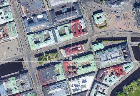
PREFACE
The thesis stems from the appreciation of and admiration for great tectonic
architecture. The pioneers within structural engineering were renaissance men,
combining their knowledge in engineering, building and architecture. We still have
much to learn from them as the building sector is faced with the environmental
challenges of our time. In bringing back holistic thinking, linking the production to
the finished structural system, can a more true efficiency be reached.

ACKNOWLEDGEMENTS
Firstly I would like to acknowledge the contribution of August Sjölin and thank
him for the collaboration during the thesis work. I would also like to thank August’s
supervisor, Jens Olsson, for his insight and support during the thesis work.

I would also like to show my gratitude to my examiner Dr. Mats Ander and supervisor
Prof. Karl-Gunnar Olsson. Their joint enthusiasm and guidance have been nothing
short of priceless. I would also like to thank Rastislav Bartek for his support.

Last but not least a big thanks to my opponents Maria Roll Bruzell and Alexander
Angrén for their conversations during this work.

           CHALMERS Architecture and Civil Engineering Master’s Thesis ACEX30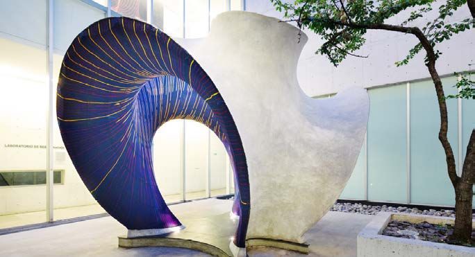
WORDLIST
Course direction - The direction of the width of a knit, that is decided by the number
of needles/loops
Eigenmode pattern - Color gradient of deformation under applied eigenfrequency
Falsework - Temporary scaffolding etc that supports the form.
Formwork - Elements that come in direct contact with the wet concrete giving its
form.
Gaussian curvature - Product of the principal curvatures in a point of a surface
Minimal surface - A surface of the minimal area within a given boundary,
mathematically represented having zero mean curvature
Pareto front - The pool of optimal solutions for several parameters
PSS- Particle spring system
Wale direction - The direction along the length of the knit that is decided by the
numbers of rows that are knitted
Short-rowing - When a knitted row stops short leaving loops from being knitted that
row

           CHALMERS Architecture and Civil Engineering Master’s Thesis ACEX30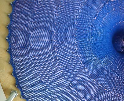
CONTENT
1. INTRODUCTION								1
    1.1 Aim									1
    1.2 Method		           						1

2. CONTEXT									3
    2.1 Efficient concrete structures                                        3
		2.1.1 Concrete structures					3
			2.1.1.1 Non-prismatic structural members		4
			2.1.1.2 Concrete shells					4
			2.1.2 Fabric structures					6
    2.2 Production methods                                                   6
		2.2.1 Casting concrete						7
			2.2.1.1 Cast-in-place					7
			2.2.1.2 Pre-cast					8
			2.2.1.3 Sliding formwork				9
			2.2.1.4 Flexible formwork				9
		2.2.2 Membrane patterning					11
		2.2.3 Knitting production					12
    2.3 Theoretical principles                                               14
		2.3.1 Shell analysis						14
		         2.3.2 Computational simulation of fabric			                       14
           2.3.3 Form-finding                                                15
		2.3.4 Particle spring system					16
           2.3.5 Eigenmode parametrisation                                   17

3. LIMITATIONS								18

4. DESIGN STUDY								19
    4.1 Site and constraints for design proposal                             19
    4.2 Methodology                                                          20

        CHALMERS Architecture and Civil Engineering Master’s Thesis ACEX30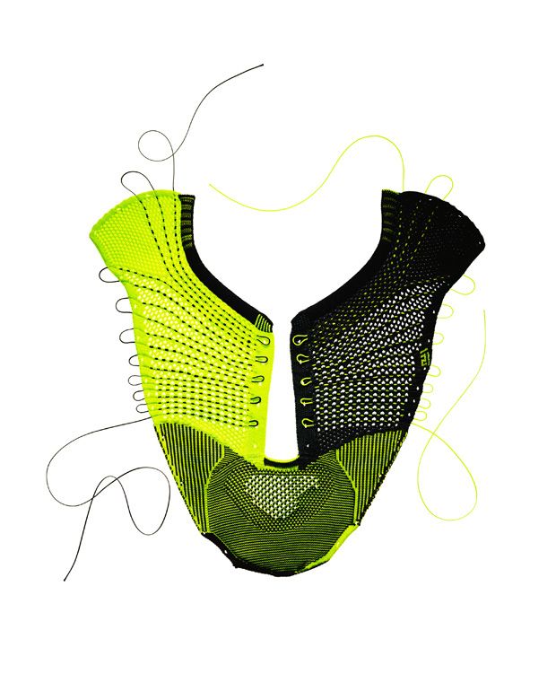
4.3 Material study                                                       21
		4.3.1 Knitting samples						21
		4.3.2 Casted knitting samples					23
		4.3.3 Computational model					27
		4.3.4 Stretch test						28
             4.3.5 Reflections from material study                             29
      4.4 Model study                                                          30
		4.4.1 Structural element					30
		4.4.2 Structural concept					32
		4.4.3 Shaping knitting pattern					32
             4.4.4 Model of umbrella structure                                 35
             4.4.5 Digital model compared with physical model                  37
		           4.4.6 Eigenmode pattern redistribution of mass		                  38
             4.4.7 Model with inflated pockets                                 39
             4.4.8 Reflection from model study                                 41
      4.5 Final design                                                         42
             4.5.1 Concept of structural system                                42
             4.5.2 Fabrication of element                                      44
             4.5.3 Erection sequence of umbrella                               44
             4.5.4 Model study of umbrella fabrication                         46
             4.5.5 Design flow                                                 51
             4.5.6 FE-analysis                                                 52
             4.5.7 Comparison to flat slab                                     56
             4.5.8 Reflection from final design                                57

5. DISCUSSION                                                                  59

6. CONCLUSION AND FUTURE WORK					                                             64

BIBLIOGRAPHY                                                                   65

          CHALMERS Architecture and Civil Engineering Master’s Thesis ACEX30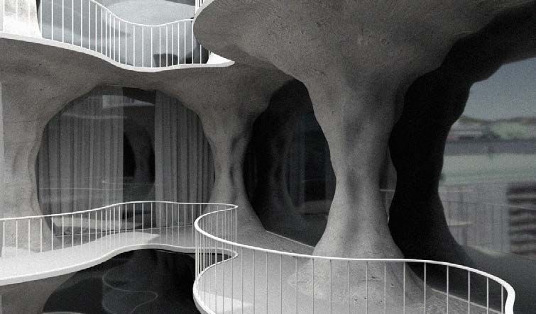
1. Introduction
“…the most fertile, ductile and complete construction method that mankind has yet
found”, is just one of many quotes about concrete from Pier Nervi’s book Aesthetics
and Technology in Building (1965). According to Nervi, this enormous potential of
concrete is due to two properties that no other material possesses, (1) its semifluid
initial state during casting and (2) the monolithic quality of the final product.

Today concrete is the material that is used the most of all materials in the construction
industry. It is also known that this industry is responsible for approximately 40% of
the global carbon equivalent emissions as well as produces 40% of the global waste
(Block, 2020). Knowing both the scale of use and the environmental impact of the
industry, it becomes crucial to use the material efficiently. When reducing material,
the structure relies on geometrical stiffness rather than the sheer volume of mass.
It is instead only placed where needed, following the logic of the internal forces.
This however imposes challenges in productions as the complexity of the shape is
increased. (Popescu, 2019)

1.1.     Aim
The main focus of this master thesis is to examine knitted formwork for casting
concrete structures. Exploring if knitted formwork can be an efficient solution to
producing complex geometries that might otherwise be difficult to achieve. The
efficiency of a concrete element that is the result from casting using knitted formwork
will also be studied. This is done to evaluate if the production method of knitted
formwork not only decreasing cost, labour and waste in production but also reduce
the volume of concrete in the structural element.

1.2.     Method
The thesis is done in two parts, a literary study, and a design study. The literary
study is done to research the field of efficient structures in concrete and membrane
structurers. In relation to this is also the production methods for concrete structures
as well as membrane structures studied. In the literary study is also the theoretical
principles applied in the design study researched. This work is presented in the
Chapter 2, the contextualization and is a starting point for the design study.

The design study is where the knitted formwork is examined. This is done in an
iterative matter, starting small and building an understanding for the knit’s structure at
a basic level. With that knowledge can complexity be added and go up in scale. The
exploration is mainly through physical models. The three stages of the design study
are: Material study, Model study and Final design. In the first stage, Material study,
is the focus to explore the possibilities of the knitted fabric in relation to concrete
casting. This is done by generating many samples in an aimless manner and then post-

                                            1
processing the result to evaluate which methods have qualities that can be used in the
design proposal. In the Model study is the design process done in a more controlled
manner where a sought-after result is strived for. However, the process is still in a
trial-and-error stage where the method for finding the wished result is iterated. In the
last stage, Final design, is the resulting design evaluated. The aim is to use the design
study as a tool to demonstrate knitted formwork and a resulting structural system
in a project setting. In Chapter 4.2 is a thorough methodology for the design study
presented.
The design study is done in parallel with architect student August Sjölin. His research
is regarding contemporary ornaments and explores if ornaments can be based on
structural performance and/or the fabrication method. For further reading please refer
to Sjölin’s thesis “Ornament and Structure – a reconnection to ornament through
knitted formwork”. The collaboration is mainly connected to model making and
illustrations.
CHALMERS Architecture and Civil Engineering Master’s Thesis ACEX30
22. Context
The contextualization of the research is done in this chapter by picking key historic or
contemporary example that relates to the research presented in this paper. Examples
of efficient structures and production methods are presented both as a source of
learning and inspiration. The context will also serve as a basis for the discussion,
where the research presented in this thesis can be weighted against.
2.1. Efficient structures
The structural efficiency for a single element can be measured as the actual stress
over maximum allowed stress. As for a structural system the mass of the structure is
related to the load carried. In the following chapters, structures that can in some sense
be described as efficient will be presented that are relevant for the thesis.
2.1.1. Concrete structures
Today the overwhelming majority of concrete is used to create straight beams and
prismatic columns. Elements that express no desire or consideration for the internal
forces. As concrete is a large greenhouse gas contributor, 4-8% of the global CO2
emissions, (Watts, 2019) which also implies that the more efficient structural systems
for concrete can have a large impact on the industry’s overall environmental footprint.
Where material used is used only where needed in a reserved and deliberate manner.
Figure 2.1 Pier Luigi Nervi, Floor system in tobacco factory, Bologna, 1949
32.1.1.1. Non-prismatic structural members
A structural member seldom has the same stresses throughout the whole length of
it. Diagrams for bending moment, shear and normal stress are common design tools
for engineers. It shows how the forces acting on the member vary along the length.
Instead of only extract peak values and design thereafter, the diagrams can inform the
design for a non-prismatic element.
In Nervi’s Tobacco factory the internal forces shape the geometry. Ribs of
reinforcements create a grid pattern, where the ribs’ cross-sections vary along the
span. The fixed ends of the ribs where the moment peaks, are also where more
material is added. The same logic is used for the beams creating a harmonious
architectural expression ruled by “logical shaping”. (Nervi, 1965)
In Figure 2.2 a beam designed by Mark West can be seen. Here the moment diagram
is used as a starting point when designing the beam. The rather organic shape reflects
the peak moments over the supports and middle of the span.
LOAD
BENDING MOMENT
Figure 2.2 Mark West’s non-prismatic beam shaped by the moment diagram from uniform load
2.1.1.2. Concrete shells
Shell structures are mostly classified through their geometry consisting of a curved
surface that is thin in the perpendicular direction. These structures work primarily
with in-plane membrane stresses since the thin section has limited bending capacity.
To eliminate bending moments the geometry of the shell needs to be carefully
designed. (Williams, 2014)
Shell structures had their prime year 1920-1960 (Veenendaal, 2017). Félix Candela
is credited to play a large role in the development and implementation of shell
structures. Candela was very productive during his career designing a large number
of shells. One of the more recognized works by Candela and his self-proclaimed
favorites is the Restaurante Los Manantiales in Xochimilco from 1958. The shell
CHALMERS Architecture and Civil Engineering Master’s Thesis ACEX30
4structure is constructed out of an eight-sided groin vault where four hyperbolic
paraboloids intersect. The thinness of the structure is striking, only 4cm thick.
The light structure could be achieved due to Candela’s exemplary intuition and
experience with concrete shells. Normally, would the dead load of the structure
caused bending in the groins. As the groins bows outward this would push at the
saddles forcing the edge to balloon out. This deformation would have caused cracks
to propagate at the edge going inwards. To prevent cracking the edge could be
stiffened with an edge beam. However, Candela did not consider the shell structure
pure if the thinness could not be expressed through the sharp edge.
Instead of addressing the edge, Candela addressed the groin. The shell thickness
increases in the groins, creating V-shaped beams. This eliminates the problematic
deformation and instead, tension forces occur at the edge. Rather pulling the edge
backward and eliminating the need to stiffen the edge. (Burger, Billington, 2006)
Figure 2.3 Félix Candela, Los Manantiales Restaurant, Xochimilco, Mexico City, 1958
52.1.2 Fabric structures
Fabric or membrane structures have long been used in architecture. It is used in the
smallest scale of architecture as a tent, ranging to some of the largest structures,
arenas. Membrane structures are extremely light but through curvature and
pretension can carry significant loads (Bechthold, 2008). Characteristic for tensile
structures is their anticlastic shape to ensure that the load is carried in tension.
Under tensile load, the fabric will strive for a minimal shape and if it is not already
adopted the fabric will wrinkle. A minimal surface is the shape of the surface that
has the smallest area within the boundary. This can be described mathematically by a
surface where the mean curvature is zero at all points. (Olsson, 2020)
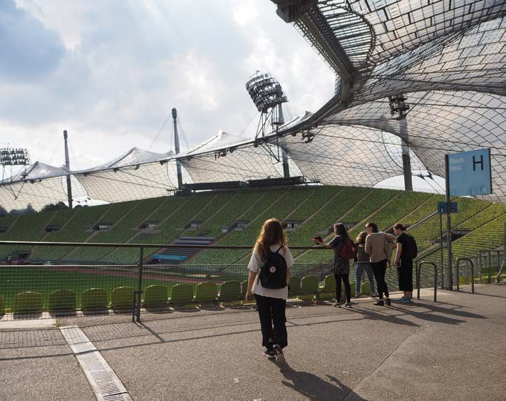
Structural engineer Frei Otto was active at the Institute of Light Weight structures in
Stuttgart. The institute and Otto himself are credited with many developments within
the field of minimal surfaces and tensile structures. (Olsson, 2020) The roof for the
Olympic Stadium in Munich for the Summer Olympics in 1972 is one of the most
recognized works by Otto.
Figure 2.4 Frei Otto, Munich Olympic stadium membrane roof structure, 1972
2.2. Production methods
It becomes evident by examining examples of efficient structures that a complexity
of geometry is added. This complexity will affect the production with parameters
such as cost, time and waste. Limiting the reach of these types of geometries to iconic
buildings where the budget allows for it. (Popescu, 2019)
CHALMERS Architecture and Civil Engineering Master’s Thesis ACEX30
62.2.1. Casting concrete
The possible geometries that can be achieved when producing concrete are limited by
the material used to produce the formwork, as it is a reflection of it (Olsson, 2020).
Many of the pioneers in shell structures also had a long experience in not only design
but also construction. This was crucial since the shell’s thinness and curvature made
the construction difficult. (Billington, 1990)
The formwork also stands for a significant part of the total cost of a structure, it is
estimated to be accountable for approximately 50% of the total coast. When the
element has a highly complex geometry the formwork cost can represent more than
70% of the total cost. (Popescu, 2019)
2.2.1.1. Cast-in-place
Shell structures are most commonly cast-in-place structures. The framework
is usually made from timber by skilled carpenters. For complex double-curved
geometry, the timber must be bent, or CNC milled. This process can be time-
consuming and wasteful. The material for the formwork can seldom be reused and
ends up as waste.
Felix Candela factored the building process into the design. Candela’s hyperbolic
paraboloids shaped shells could be constructed by linear elements since the surface
is a ruled surface. This significantly reduced the cost and facilitated the construction
process.
Figure 2.5 Félix Candela, Los Manantiales Restaurant, Xochimilco, Mexico City, 1958
72.2.1.2. Pre-cast
Casting off-site and bringing complete elements onto site can be an option to reduce
some of the need for extensive scaffolding (Billington, 1990). The same mold
can also be used to produce several elements and the level of accuracy is higher.
However, there are some limitations to pre-casting elements. The size of the elements
is restricted to transport but also the on-site connections are more demanding.
(Olsson, 2020)
The dome structure in Nervis’s Palazzo dello Sport consists of a combination of pre-
cast and casting on site. The dome structure is approximately 100 meters in diameter,
with pre-cast ferrocement units originating from the center and radiating outwards.
Ferrocement is constructed by encasing a thin mesh of rebar in mortar. The rows of
V-shaped units vary in depth from 0.3m to 1.2m at the edge. On top of the V-shapes
are precast slabs placed. In-situ reinforced concrete is cast in the valleys and crests
making the outer surface homogenous. The dome structure was completed in only 2.5
months. (Campbell, 1959)
The dome is not only an example of fast and efficient construction but also an
efficient structural system. In a half-sphere, the hoop stresses in the top are in
compression and change to tension in the bottom part. As the dome of Palazzo dello
Sport is cut at the level where the hoop stresses changes sign the result is a dome
structure in pure compression under gravity load.
Figure 2.6 Roof structure of Palazzo dello Sport, Nervi, 1959
Figure 2.7 Section drawing of V-shaped units and the entire buildings
CHALMERS Architecture and Civil Engineering Master’s Thesis ACEX30
82.2.1.3. Sliding formwork
To reduce the cost of the formwork can a partial mold be used that can slide. A
sliding formwork was used for the Tobacco factory to reduce the cost of the intricate
geometry. The slab was cast in segments as seen in Figure 2.8. When the slab was
self-supporting the mold was lowered and slid on the tracks to the next position.
Figure 2.8 Nervi, Sliding formwork for Tobacco factory, 1949
The geometry of the building limits the use of sliding formwork. Linear buildings
with for instance flat slabs or barrel roofs are well suited. As well as domes where a
pie-shaped formwork slides in a circle.
Another drawback is that the structure must be self-supporting when incomplete.
For instance, a dome structure would have to be self-supporting without any hoop
stresses. (Billington, 1990)
2.2.1.4. Flexible formwork
Within the field of flexible formwork, there are different approaches. Some of the
approaches are using a woven fabric, cable net and knitted formwork.
The beam seen in Figure 2.2 is formed by fabric formwork. But also larger elements
such as the three columns in Omer Arbel’s project 75.9. The elements are formed
by pouring concrete into a fabric that was restrained by plywood ribs. The concrete
was poured at a slow pace to let it cure simultaneously to limit the hydrostatic
pressure on the base. The fabric releases air bubbles from the concrete through
micro-perforations. (Arbel, 2018) If the fabric is water-permeable excess water in the
concrete can escape that’s not chemically bound. This can increase the quality of the
concrete as too high water content will reduce the concrete strength. (West, 2016)
A significant amount of research at ETH Zurich has been done in the area of flexible
formwork. A hyperbolic paraboloid shell was constructed by casting concrete on a
9Figure 2.9 Omer Arbel, 75.9 construction process, Surrey, Canada, 2018
pre-tensioned grid of cables. The shape is well known from buildings by Candela
among others. However, the shell geometry was not limited to a ruled surface
which was used when constructing the formwork from straight timber members.
The freedom enabled the shell to be optimized and have increased stiffness. (Block,
Veenendaal, 2014)
ETH Zurich along with ZHCODE constructed a 5 tone sculpture using knitted fabric
formwork as guide work. The knitted formwork had an integrated cable network and
air pockets and the total weight of the formwork was 55kg. (Popescu, 2019)
Figure 2.10 ETH & ZHCODE, KnitCandela, Mexico, 2018 (photo credits: Angelica Ibarra).)
CHALMERS Architecture and Civil Engineering Master’s Thesis ACEX30
102.2.2. Membrane patterning
Where woven fabrics or other foils are used for tensile membrane structure, a
cutting pattern is necessary to cut, sew and assemble the structure. The patterning
can be quite difficult to be designed since it’s based on the final tensioned shape and
therefore must be offset with regards to strain and Poisson’s ratio. The final geometry
which is often a double-curved geometry also needs to be discretized into smaller
developable surfaces that can be cut from the fabric.
Figure 2.11 Woven and knitted fabric with zoom on knitted fabric
When using knitting the fabric can be manipulated by the different operations as
seen in Figure 2.16. The operation to increase, decrease and slip can redirect material
and create 3D shapes. This results in a significant part of the manual labor can be
eliminated when knitted fabrics are used for a double-curved surface.
At ETH Zurich an open-source tool for generating knitting patterns has been
developed. A mesh based on the loop height and width is generated on the desired
surface. Each loop is representing a square, with each triangle representing an
operation, either increase, decrease or slip. When loops are slipped it is called short
rowing as that row stops short. Loops from the previous row will stretch over to the
next knitted row, adding volume to where the loops are not slipped.
Figure 2.12 Short-rowing description
Figure 2.13 Knitting patterning generated using Rhino/Grasshopper plug-in Cockatoo
112.2.3. Knitting production
Knitting is believed to have been around since the 5th century as a method to produce
fabrics. It has a rich history and traditions with different techniques. As in most
industries, significant developments have been made to automate to process for mass
production. However, the different techniques of how to interlock the loops of yarn
are still the same but now produced with machines rather than by hand.
A flatbed knitting machine consists of the needle bed and the carriage. The carriage
travels back and forth over the needle bed with the yarn. When the carriage moves
over a needle it causes this needle to be pushed out and in, this movement enables the
needle to catch the yarn and pull the previous loop over the yarn creating a new one.
Usually the there is two needle bed facing each other. The upper array of needles
is the main bed and the lower array the ribber bed. The most simple knit, the single
jersey is knitted using only the main bed. The more elastic knit, the double jersey is
knitted one every other needle on the main and ribber bed.
The knitted running shoe is a good example of CNC knitting. The shoe features
change in geometry, colors and yarns and integrated channels/holes for the lace. All
of this is done in on simultaneous knit in one go. A CNC knitting machine is fed with
a pattern made up of pixels with different colors. Each pixel controls one needle and
the color describes the movement of the needle.
Figure 2.14 Single needle forming a new loop and set-up with two needle beds
CHALMERS Architecture and Civil Engineering Master’s Thesis ACEX30
12The complexity of the operations depends on the machine. The SK840 with a ribber
SRP60N that Chalmers University has can be programmed to knit or not knit (slip)
using a color chart and pick between yarns. However, transfers have to be done by
hand. On an industrial-grade machine all of these operations can be programmed.
Once the pixel map of the pattern is generated, the machine will knit without any
human interaction needed.
Figure 2.15 Nike knitfly, Knitted shoe upper, 2012
Figure 2.16 Examples of pixel and pixel sequences for pattern making
132.3. Theoretical principles
In the following chapters, theory applied in the design study will be presented. The
theory will be used both as a comparison to physical models and as a design tool.
2.3.1. Shell analysis
Shell structures are mostly classified through their geometry consisting of a curved
surface that is thin in the normal direction. For a shell, all the modes of other
structures, such as beams, struts, cables, plates are available with the addition of
‘shell action’. In-plane membrane stresses are a central part of shell theory. There
are three unknown stresses, the normal stress in x- and y-direction and shear stress
perpendicular to each of the normal stresses, which through moment equilibrium
can be determined to be equal. From the plane stresses there are two equations of
equilibrium.
For the membrane theory of shells, the same in-plane stresses are used. However,
with the addition of the equilibrium equation. The equation is in the perpendicular
direction of the tangent of the shell surface. The force is balanced with the membrane
stresses multiplied by the curvature. Since the curvature has the unit m-1, the load
would have unit kNm-2, and the membrane stresses kNm-1.
The curvature of a shell is often described by using Gaussian curvature. The Gaussian
curvature is the product of the two principal curves of the surface. A synclastic
surface has positive Gaussian curvature, an example of this is a dome. The anticlastic
surface has negative Gaussian curvature, such as a saddle. For a surface with zero
Gaussian curvature, the surface is also developable and could be laid flat, for
example, a cylinder. (Williams, 2014)
Figure 2.17 Dome (positive Gaussian curvature), cylinder (zero Gaussian curvature),
saddle (negative Gaussian curvature).
CHALMERS Architecture and Civil Engineering Master’s Thesis ACEX30
14Due to the thinness of the shells, the bending stiffness is limited. Therefore it is
desirable to have a funicular shell that carries the load in membrane action with
no bending moment. Concrete’s mechanical properties allow for much greater
compression forces than tension forces. Therefore concrete shells are usually
designed to be in primary compression. To limit the need for reinforcement is
beneficial as this can be very complex for doubly curved surfaces as shells.
One of the most common failure modes for concrete is local buckling. Since the
shell is often in compression with a thin cross-section, local instability is often of
great concern. (Williams, 2014) One option that is often seen in for instance Nervi’s
structures is increasing the stiffness by introducing ribs. The ribs stiffen the surface
without adding as much material as if the entire shell thickness is increased.
2.3.2. Computational simulation of fabric
Simulation of fabric can be a complicated matter. Simulation on a larger scale, like
the one of architecture, the textile is usually simplified to a continuous surface or
course mesh containing the mechanical properties. The material properties are usually
orthotropic, for instance, the stiffness in each directions. (Hörteborn, 2020)
When simulating a knitted fabric, it is even more complicated than for a woven
fabric. For a woven fabric several threads are acting parallel to each other as for the
knitted fabric a single thread is looped together. The behavior of interlocking loops
and the friction of sliding the loops are difficult to capture.
By translating the knit into a hexagonal grid containing “interlocking” elements that
can slide along the neighboring elements have Cirio et al (2016) been able to digitally
simulate the behavior of the knit on a loop level. This is done to represent knitted
fabric for computer graphics.
2.3.3. Form-finding
The field of form-finding is especially important for membrane and shell structures.
For a tensile membrane, the form-finding process is crucial to make certain that the
membrane will contain its shape and eliminate wrinkling of the surface.
For shell structures, the form-finding is to eliminate bending moments to ensure that
the shell works primarily with in-plane stresses. Concrete as known is weak in tension
but very strong in compression. Therefore, the goal of form-finding a concrete shell
is often to have a structure in primary compression. The hanging model analogy is
often used for this purpose both in physical models and computational models. The
most primitive version of the analogy is when inverting the shape of a hanging chain
the structure will go from pure tension to pure compression. (Bechthold, 2008)
15Antoni Gaudí modeled Sagrada de Familia using string and weights. The weight
was the self-weight of the structure and the strings adopted their shape according
to the weights. Heinz Isler used sheets as a tool for form-finding his shell structure.
(Chilton, 2010) The sheets were hung, and the shape inverted going from a sheet in
tension to a shell in compression as seen in Figure 2.18.
Figure 2.18 Heinz Isler, Physical form-finding by hanging fabrics and construction of
concrete shell designed, Norwich Sports Park, Norwich England, 1991
2.3.4. Particle spring system
The objective of the particle spring system is to find a shape in statical equilibrium.
A system is discretized into a network of springs and particles. The springs have an
associated length and stiffness, and the particles have a mass and load. The system
has converged when the sum of the forces in the system equalizes. For instance, can
the particles can be loaded with gravitational pull causing the springs to elongate.
This elongation of the spring generates a force in the spring and the system converges
when the force in the spring eliminates the downward force from the gravitational
pull. The motion of the particles is governed by Newton’s second law and the force of
the spring is governed by Hook’s law.
INITIAL STATE
MASS = 0
MASS = M REST LENGTH = 0
REST LENGTH =L
EQUILIBRIUM STATE
Figure 2.19 Hanging model simulation and stretching of fabric using PSS
CHALMERS Architecture and Civil Engineering Master’s Thesis ACEX30
16When applying the method of PS systems there are a few parameters that control
the outcome. Boundary conditions are important and will affect the result greatly.
This determines which nodes are free to move and which are fixed in space. The
parameter of the rest length and the loading of every node determines the “goal” of
the simulation. This model can be used to simulate hanging models such as Gaudi and
Isler used, but also stretching of fabric as seen in Figure 2.19.
For the simulation of knitted fabric, a small rest length is set. This will simulate the
stretching of the fabric between the prescribed boundary curves. The load in the
particles is not relevant in this case since the tension of stretching the fabric will be
much greater than the load caused by the weight of the fabric. (Block, 2016)
2.3.5. Eigenmode parametrisation
When shells are designed as pure compression shells it is usually for the dominating
load case, for instance, the self-weight. The structure also has to resist additional
loading, non-symmetrical loads and geometrical imperfections. The full spectrum
of load cases will most likely impose some bending moments in the structure. In
addition, the shell has to be designed for instability such as local buckling. The
shell can be dimensioned so that it can handle such load by having a thicker shell
or stiffeners can be used. Much like the roof of the sports arena by Nervi where the
dome interacts with a diagrid of beam/stiffeners.
When designing a shell with ribs the placement of the stiffeners needs to be
superimposed on the shell geometry. This can be difficult as the surface geometry’s
complexity can make it difficult to orient. One way to parametrize the surface to
find the placement of ribs or openings was proposed by Panagiotis Michalatos and
Sawako Kaijima (2014) is to use the vibration eigenmodes. The patterns themselves
are not per default the optimal solution but need to be post-processed to find which
pattern performs the best.
The advantages of using the eigenmode pattern are that the result of the optimization
process will be a logical pattern as opposed to a random-looking and scattered result.
The result is also visually strong and could contribute to the architectural expression.
Figure 2.20 First 20 vibration patterns for square plate
173. Limitations
The thesis will compare casting with knitted formwork to other production methods
regarding aspects such as waste, labour, time and environmental impact. However, a
full carbon footprint in a life cycle analysis is not in the scope. The comparison will
instead be based on literary study and empirical results from the design study.
As the thesis aims to explore knitted formwork in a project setting is a site in
Gothenburg is chosen. The site will serve as a reference for dimensions etc. The
design study will result in one conceptual design for a key element in the building but
not resolve the structural system in its entirety. Foundation and ground conditions will
not be considered.
The design study is also done in collaboration together with August Sjölin, a student
doing his Master’s Thesis in architecture at Chalmers University. This imposes other
demands from an architectural point, for example spatial, acoustical and artistic that
will make the project more complete in its entirety. The collaboration is not only a
source of limitations but first and foremost a great source of inspiration, guidance and
help to achieve a well-rounded project.
For examination of the knitted fabric’s behavior is an SK840 knitting machine with an
SRP60N ribber attached is used. The machine is not suitable for producing an entire
formwork for a building element since the size is limited to 200 needles wide and is
relativity manual compared to industrial-type knitting machines. However, whatever
can be done on the simple machine could be translated to an industrial machine if to
implemented on a larger scale.
Figure 3.1 Knitting machine set-up
CHALMERS Architecture and Civil Engineering Master’s Thesis ACEX30
184. Design study
The design process is a tool to examine the knitted formwork for concrete casting in
a project setting. A conceptual design for key element is presented at the end of the
study. As the study is done in an iterative matter will the resulting design embody the
findings throughout the process. The project is done in collaboration with architect
student August Sjölin at Chalmers University with the expectation is that architectural
values will be reflected in the study.
4.1. Site and constraints for the design proposal
The location of the design proposal is in Gothenburg, Sweden at Södrahamngatan
47. This location is also known as Brändatomten as the previous building was badly
damaged in a fire resulting in the need to tear it down. The gap that was left between
the two adjacent buildings has since been in the location of many design proposals.
The characteristics of the site are that it is very narrow but deep, with dimensions
12 meters by 35 meters. The adjacent building both have a public ground floor with
approximately 4.5 meters in ceiling height. The right building is in total 4 stories and
the left building 5 stories.
Figure 4.1 Location of design proposal Södrahamngatan 47, Gothenburg
Figure 4.2 Location of design proposal Södrahamngatan 47, Gothenburg
194.2. Methodology
The study is done in an iterative matter and have a research-by-design approach.
A large emphasis is on model making. Nervi wrote in Structures (1956) that the
education for engineers should be focused around model making as this gives a
structural intuition, especially form resistant structures. Especially as form resisting
structures was not yet a part of the subconscious of our structural thinking. In
addition, is knitting in a building environment relatively unexplored making it well
suited to investigate with models as the reference base is limited.
Nervi (1965) also emphasized the architectural qualities should not be ignored rather
embraced by the structural engineers. As the design study is being done in close
collaboration with architect student August Sjölin are the architectural values present
throughout the work.
The design study is done in three stages where the scale and level of detail will vary.
In the first stage, the emphasis is on the knitted fabric which is examined on a scale
of 1:1. This is done in a quantitative matter where a significant amount of tests will
result in a large pool of results to draw conclusions from.
In the second stage, the context of the site enters forcing the narrative to broaden.
External demands on an architectural scale are the focus, however, remaining in a
conceptual design phase.
In the last stage, is a final design proposal presented. The design is still conceptual
but with some verifications and quantifications as an indication of the viability of the
design proposal.
MATERIAL STUDY MODEL STUDY FINAL DESIGN
KNITTING SAMPLES ELEMENT PROTOTYPE LARGE SCALE MODEL
CASTED SAMPLES PATTERNING STRUCTURAL ANALYSIS
COMPUTATIONAL MODEL FORM-FINDING ERECTION SEQUENCE
Figure 4.3 Workflow diagram with purple for physical model work and green for
computational work
CHALMERS Architecture and Civil Engineering Master’s Thesis ACEX30
204.3. Material study
In the following subchapters the material study is presented. The focus is on small
material tests but on a scale of 1:1 to capture the material behavior and develop a
understanding of the structure of the knit and its interaction with concrete.
4.3.1. Knitting samples
A large sample of knittings are produced. The intention of the samples is to get
a better understanding of the behavior of the knitted fabric and how it could be
manipulated. Some of the knitting samples are presented below with a short comment
on the special characteristics of the sample.
Figure 4.4 Single jersey
Stockinette or single jersey, the simplest
knit.
Figure 4.5 Single jersey with drop stitch
Varying density of the knit. The area
where loops were knitted on both the
main bed and ribber bed and then the
ribber loops were unraveled. Adding
volume to adjacent loops then gets
looser with approximately double the
size of the regular loops.
Figure 4.6 Single jersey fair isle
Multiple colored knit using fair isle
where the inactive color runs loose on
the backside.
21Figure 4.7 Jacquard knit
Much more elastic knit compared to
the single jersey, especially in course
direction. The knit has a front and
back and the inactive color is enclosed
between the two layers.
Figure 4.8 Single jersey with slip stitch
The sample has a 3d effect. The area
where the stitches are not slipped
bulged out of the plane of the knit.
Figure 4.9 Tubular knit, single jersey
The top half was knitted with a higher
tension than the bottom half. When
the tube was tensioned the frame
tilted towards the tighter side which
is straighter while the looser half gets
more curvature.
Figure 4.10 Tubular knit with drop stitch
The tube was tensioned and become
somewhat faceted. Tension bands
form where there are continuous strips
without drop stitches can be located.
CHALMERS Architecture and Civil Engineering Master’s Thesis ACEX30
224.3.2. Cast knitting samples
As the intention is to use the knit as formwork for concrete casting, some knitting
samples are tensioned in a frame with wet concrete poured into or coated onto. This
is done to document the effects on the knit and the finished concrete. The first tests
are simple squares with different knitting techniques to manipulate the fabric. In the
progression are different geometries tested, both solid models and more shell-like
models were produced.
Figure 4.11 Single jersey, every needle
No visible deflection under the weight
of wet concrete.
Figure 4.12 Single jersey, every other needle
Significant homogeneous deflection
under the weight of wet concrete, some
leakage.
Figure 4.13 Mixing every and every other
needle
Homogenous deflection.
23Figure 4.14 Drop stitch
Large difference in deflection under the
weight of concrete. In the drop stitch
area, a bulge is formed. Plastic foil was
used to prevent leakage.
Figure 4.15 Short-rowing
A bump was created using short rowing
on the sides. In the first sample, the
bump was knitted with double the
amounts of rows compared to the
second. The bump was reflected in
the casted product as well. However,
significant leakage in the first slipped
loop per row.
Figure 4.16 Crochet
On a single jersey knit tight bands of
crocheting are added. The lines are
reflected in the casted samples as lines
limiting the deflection.
Figure 4.17 Inflated pocket
Pocket on a single jersey where an
inflated balloon was added. The balloon
is reflected with an indent in the casted
sample. The squared perimeter of the
pocket is also visible. Plastic foil was
used as lining.
CHALMERS Architecture and Civil Engineering Master’s Thesis ACEX30
24Figure 4.18 Partial double jersey
Single jersey with two areas of rib,
one with full rib and single rib. The rib
reflects in the texture of the concrete
sample, however, the deflection is
homogenous.
Figure 4.19 Solid model with drop stitch
The concrete adopts the shape of the
dope stitch areas where the concrete
protrudes more in the less stiff areas.
Figure 4.20 Tube with drop-stitch
A latex membrane is used to pour the
concrete into. Areas with drop-stitch
are less stiff and do not restrict the
membrane to the same extent resulting
in a bumpy cylinder.
Figure 4.21 Large square to smaller circle
Four panels are joined to a tube. The
formwork is tensioned from top to
bottom and cast. The resulted geometry
smoothly transforms from a square to a
circle.
25Figure 4.22 Saddle shape formwork
A wooden laser cut frame is cut. The
sides have the same curve but in
different directions. When the knit
is stretch and fastened by the nails it
adopted an anticlastic curvature.
Figure 4.23 Casted saddle shape
A single jersey knit was tensioned in
the frame and glass fiber mixed with
concrete was placed on the fabric.
The result is an anticlastic shell
approximately 3mm thick with some
variation.
Figure 4.24 Saddle shape with drop stitch
The knit is tensioned in the frame with
a highly elastic membrane to prevent
leakage. When cast no visible deflection
for the drop stitch area.
Figure 4.25 Tubular
Concrete was poured into the tubular
knit while rotated for 30 minutes,
resulting in a shell tube. The knit is
fully embedded in the concrete.
CHALMERS Architecture and Civil Engineering Master’s Thesis ACEX30
264.3.3. Computational model
Form finding of the knit is done by using PSS, described in chapter 3.2.1. The system
was set up in Rhino/Grasshopper using Kangaroo’s dynamic relaxation solver that is
appropriate for large displacements of non-linear systems. Four different mesh option,
seen in Figure 4.26, was evaluated to be the most appropriate to use in a simulation of
knitted fabric.
Figure 4.26 Tubular mesh form found with particle spring system where rest-length is set to 10%
of original length, a. Hexagon mesh b. Quadrilateral mesh c. Diagrid mesh d. Triangulated mesh
The triangulated mesh warps as the diagonals are not equally distributed. The other
three all behaved in a very similar way, with the difference in circumference of
the waist. This could also be controlled by the rest length or relative stiffness of
the springs. Therefore, is the quad mesh chosen as it is much simpler to map on an
irregular surface than for instance hexagonal mesh. It also follows the same logic
as the loops in the knit and the mesh can therefore be more direct interpretation.
The mesh can be directly translated from a knitting pattern where x by x loops can
represent one facet in the quad mesh.
The spring system simulation is applied to recreate some of the material samples with
drop stitch. To simulate the added volume in the loops of the drop stitches, the rest
length was modified to be double the one for the rest of the mesh. In Figure 4.27 a.
the springs are pre-tensioned by giving them a rest length of 0.5 their original length,
making the dropped stitches rest length their original. In Figure 4.27 b. is the spring
system loaded with pressure to simulating the load of the wet concrete. The results of
the simulations is a distortion of the mesh in-plane respective distortion out-of-plane.
The result can be compared with casting samples in Figure 4.24 and 4.14.
Figure 4.27 Drop stitch simulation with a. in-plane distortion and b. relative out-of-plane
displacement
274.3.4. Stretch test
Knitted fabric has two main directions with different stiffness in each direction.
In order to evaluate the relative stiffness of the directions is a stress/strain test
performed. Two pieces of single jersey of the approximate size of 10cm by 10cm
are made. The fabric pieces are fastened on a squared background with one side to
the backboard and the opposite a frame along the edge. The frame of the free edge
a newtonmeter was fasted and pulled. The stretching of the fabric was measured
against the squared 5 by 5mm background with corresponding force measured by the
newtonmeter.
The two pieces of fabric were oriented in different directions in order to evaluate the
two main directions, measuring the stress/strain in the wale and the course direction.
The result is plotted in diagram in Figure 4.28. As can be seen, the material has a
non-linear behavior where the initial stretching of the fabric can be done without
much force applied. This is to be expected as the loops contract in the perpendicular
direction of the applied force. As the loop tightens more linear behavior can be seen
as the loop cannot reconfigure in the pediculate direction as much as initially.
FORCE [kN/m]
WALE
COURSE
APPROXIMATE
RELATIVE STIFFNESS:
W/C=0.9
LENGTH [cm]
Figure 4.28 Uniaxel stress-strain plot for knitted fabric in course and wale direction
To further improve the PSS simulations is the relative stiffness in the course and wale
direction extracted from the test. The approximate value is based on the slope in the
later stage of the stretching where the elongation is a more linear. The initial non-
linear behavior is reasoned can be discarded as the original state of the knit will be
assumed to be after the initial stretching. For instance, will the loop size be based on
a slightly stretched sample piece to not account for this when mapping the knitting
pattern.
The stretch test was conducted using mercerize cotton yarn knitted with tension
setting on 2. For other yarns and settings on the knitting machine would show a
different result. The same yarn and similar settings are used throughout the thesis.
However, in further development would a more precis stress-strain test for a large
number of fabric samples be desirable.
CHALMERS Architecture and Civil Engineering Master’s Thesis ACEX30
284.3.5. Reflections from material study
It is clear that the knitted fabric can be manipulated in many different manners. Shape,
density and stretch are some of the ways that the knit properties can be changed.
The properties are also often intertwined not least the density and the elasticity. As
seen in Figure 4.11 and Figure 4.12 is the knit of every other needle compared to
every needle much more flexible and deflects significantly. The looser, less dense
knit is also the one with the most stretch. The opposite relationship can be seen in
the jacquard knit where the density is almost that of two fabrics but also significantly
more flexible than that of a single knit. As the jacquard knit is structured more like
a full rib where the yarns run back and forth between the main bed and ribberbed.
This can be seen in the fabric as it has two right-facing sides and will add length to
the yarn. However, this length is mostly added in the course direction making the
jacquard significantly more flexible in that direction but with similar stiffness in the
wale direction as a single jersey.
One key difference in the manipulation is the difference in global and local geometry.
The global properties are how the overall geometry of the knit acts under for instance
the pressure of fresh concrete or when tensioned. The local is where the geometry
can deviate from the global geometry. One example of this is in Figure 4.14 where
the area of the drop stitch is bulging out, interrupting the global geometry. Such effect
can not be seen in Figure 4.13 where the loose, every other needle knit is mixed with
the tighter every needle knit. The result is instead a homogenous deflection where no
local effect can be seen between the two areas. The difference between a loose-knit
and drop stitch knit is that the loop size is larger for the drop stitch in both course
and wale direction whereas every other needle volume is only added in the course
direction. Volume needs to be added in both directions as the stiffer direction will
otherwise act as the main load-carrying direction making the tension in the other
direction less important. This conclusion can also be supported by observation from
Figure 4.18. Where the ribbing is adding volume again in course direction without
seeing any local deflection.
Short-rowing, seen in Figure 4.8, proves to be an efficient way to create curvature
within the knit. The local geometry can be changed by having additional rows in
certain areas. However, as seen in Figure 4.15, can drastic changes in the geometry
create strain localized in a single loop. Leading to the conclusion that short-rowing is
well suited to shape the global geometry that often has a more gentle curvature. While
more drastic local geometry should be done with some care.
Other knitting techniques of interest moving into the next stage considered are
the inflated pocket and drop stitch as they in contrast to short-rowing displays the
ability of locally impact the geometry. The air pocket and drop stitch show inverted
results as one removes concrete by making an indent and the other adds material by
protruding out.
29By comparing the figures from Chapter 4.3.3 with corresponding knitted samples in
Chapter 4.3.2 the conclusion can be drawn that the PSS can be used successfully as
a simulation for knitted fabrics. Further development is to implement the stretch test
to the PSS. Since the stretch test was quite analog and not very precise should the
values extracted not be used for any detailed analysis. However, it could inform the
PPS of the relative stiffness in the course and wale direction to calibrate that model
somewhat.
4.4. Model study
In the following chapter is the second iteration of the design study presented. The
focus is to translate the findings from the material study and apply that knowledge to
elements. The context of the site and other external demands enters at this stage.
4.4.1. Structural element
When using pre-tensioned knitted formwork, the consequence is that the element gets
an anticlastic shape as this is how tension only membrane works. In order to explore
the design space are some initial shapes generated using quadrilateral mesh and PSS
system with zero-length elements. The result can be seen on the next page where an
intuition of the design language can start to develop.
Figure 4.29 Anticlastic shapes A. Hypar B. Coinic C. Barrel vault
Moving forward will the “umbrella” structure be used, where a single column
expands out to a slab. The structure has the potential to fully demonstrate how knitted
formwork can be used.
Listed below are the reasoning for why the umbrella structure is considered the
strongest candidate:
- Produce a “complete” independent structure as one unit.
- Utilize the existing boundaries (walls and floor) to tension the formwork.
- Complex and very large formwork if using traditional casting methods.
In addition to the umbrella structure will a “half column” element be used. This
element will be used to implement ribs in the shell structure. The half colum is used
out of practical reasons since the back is easily accessible and a similar formwork as
seen in Figure 4.22 can be used to produce it.
CHALMERS Architecture and Civil Engineering Master’s Thesis ACEX30
30Figure 4.30 Element design options generated using PSS with zero-length elements
314.4.2. Structural concept
The umbrella shape is intended to work as a shell structure in predominant
compression. Form finding using stretching of fabric for shell structures has been
done before for instance in the Ponte sul Basento bridge. The points where the fabric
is being pulled are in the finished structure where the load is applied, going from a
fabric in tension to a shell in compression. Here the load from the bridge girder is
considered to be the dominated load and the self-weight of the shell superstructure
negligible in comparison.
Figure 4.31 Sergio Musmeci, Bridge on the Basento river, physical models and realization, 1974.
KNIT FRONT
In the umbrella structure fabric is not only used to form-find but also as formwork.
When tensioning the formwork, the resultant force should be inverted to compression
when the shell is cast. As the gravity load is not angled a third horizontal force will
complete the equilibrium. As seen in Figure 4.32 the gravity load will be balanced
with compression in the shell and tension in the slab. As the slab is flat and not doubly
KNIT Y1 FRONT
curved like the rest of the structure this will be easier to reinforce to carry the tensile KNIT Y2 BACK
forces.
FORMWORK FINISHED STRUCTURE
FROM FRONT
TO BACK
Figure 4.32 Sketch of structural concept
CHALMERS Architecture and Civil Engineering Master’s Thesis ACEX30
324.4.3. Shaping knitting pattern
The knitting pattern generated using the open-source tool from ETH Zurich
in Chapter 2.2.3 is not optimal for the knitting machine available at Chalmers
University. A custom script for knitting patterns is produced that considered the
limitations of the SK840 knitting machine. For shaping the geometry is only short-
rowing used and not moving, decreasing, or increasing the number of loops, since
these operations needed to be done manually. Manually operations are very time-
consuming and likely to attract mistakes due to the human factor. Short-rowing on the
other hand could be done automatically using the interactive software DesignaKnit8.
The pattern is generated by dividing the top and bottom edge curves based on the
loop height. The points on the bottom curve find the point on the top curve that will
generate the shortest path on the surface. These lines are then divided based on the
loop width. The distance between neighboring points is calculated and divided again
based on the loop height. First, the straight segments are generated by the rows which
contain the same number of points. Then the branching paths are generated by the
shortest segments that will continue the path. Step by step is seen in Figure 4.34.
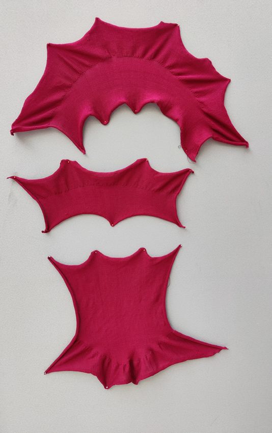
In Figure 4.33 the shape of the umbrella model. The pattern was generated in three
pieces with the knitting pattern for the top part visible. Each line is in a color that
represents the length and number of loops for that row. The pattern is constructed so
that each line represents two rows of knitting. This is done to eliminate yarn to run
loose which it will if the row doesn’t start in the same position that it ended.
The generated knitting pattern is also later used as a mesh to represent the knit. When
generating the mesh the loop size is not relevant but instead, the size input represents
how coarse the mesh is. For the mesh representation both the branching elements
are used not only the shorter one as the loop is connected on both sides and would
otherwise cause a hole in the mesh.
Figure 4.33 Pattern for top purple part of model
33You can also read