SBI-7127RG GPU Blade Module - User's Manual Revison 1.0a
←
→
Page content transcription
If your browser does not render page correctly, please read the page content below
SBI-7127RG
GPU Blade Module

 User’s Manual
     Revison 1.0a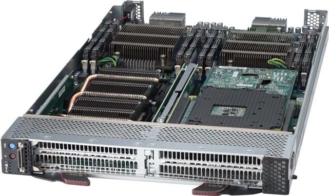
SBI-7127RG GPU Blade Module User’s Manual

The information in this User’s Manual has been carefully reviewed and is believed to be accurate. The
vendor assumes no responsibility for any inaccuracies that may be contained in this document, makes no
commitment to update or to keep current the information in this manual, or to notify any person or
organization of the updates. Please Note: For the most up-to-date version of this manual, please see
our web site at www.supermicro.com.

Super Micro Computer, Inc. (“Supermicro”) reserves the right to make changes to the product described
in this manual at any time and without notice. This product, including software and documentation, is the
property of Supermicro and/or its licensors, and is supplied only under a license. Any use or reproduction
of this product is not allowed, except as expressly permitted by the terms of said license.

IN NO EVENT WILL SUPERMICRO BE LIABLE FOR DIRECT, INDIRECT, SPECIAL, INCIDENTAL,
SPECULATIVE OR CONSEQUENTIAL DAMAGES ARISING FROM THE USE OR INABILITY TO USE
THIS PRODUCT OR DOCUMENTATION, EVEN IF ADVISED OF THE POSSIBILITY OF SUCH
DAMAGES. IN PARTICULAR, SUPERMICRO SHALL NOT HAVE LIABILITY FOR ANY HARDWARE,
SOFTWARE, OR DATA STORED OR USED WITH THE PRODUCT, INCLUDING THE COSTS OF
REPAIRING, REPLACING, INTEGRATING, INSTALLING OR RECOVERING SUCH HARDWARE,
SOFTWARE, OR DATA.

Any disputes arising between manufacturer and customer shall be governed by the laws of Santa Clara
County in the State of California, USA. The State of California, County of Santa Clara shall be the
exclusive venue for the resolution of any such disputes. Super Micro's total liability for all claims will not
exceed the price paid for the hardware product.

FCC Statement: This equipment has been tested and found to comply with the limits for a Class A digital
device pursuant to Part 15 of the FCC Rules. These limits are designed to provide reasonable protection
against harmful interference when the equipment is operated in a commercial environment. This
equipment generates, uses, and can radiate radio frequency energy and, if not installed and used in
accordance with the manufacturer’s instruction manual, may cause harmful interference with radio
communications. Operation of this equipment in a residential area is likely to cause harmful interference,
in which case you will be required to correct the interference at your own expense.

California Best Management Practices Regulations for Perchlorate Materials: This Perchlorate warning
applies only to products containing CR (Manganese Dioxide) Lithium coin cells. Perchlorate
Material-special handling may apply. See www.dtsc.ca.gov/hazardouswaste/perchlorate for further
details.

WARNING: HANDLING OF LEAD SOLDER MATERIALS USED IN THIS PRODUCT MAY
EXPOSE YOU TO LEAD, A CHEMICAL KNOWN TO THE STATE OF CALIFORNIA TO
CAUSE BIRTH DEFECTS AND OTHER REPRODUCTIVE HARM.

Manual Revison 1.0a
Release Date: January 11, 2013

Unless you request and receive written permission from Super Micro Computer, Inc., you may not copy
any part of this document.

Information in this document is subject to change without notice. Other products and companies referred
to herein are trademarks or registered trademarks of their respective companies or mark holders.

Copyright © 2013 by Super Micro Computer, Inc.
All rights reserved.
Printed in the United States of America

                                                       ii
Preface
     About this Manual
This manual is written for professional system integrators, Information Technology
professionals, service personnel and technicians. It provides information for the
installation and use of Supermicro's SBI-7127RG GPU blade module. Installation and
maintenance should be performed by experienced professionals only.

     Manual Organization
Chapter 1: Introduction
The first chapter provides a checklist of the main components included with the
SBI-7127RG GPU blade module and describes its main features.
Chapter 2: System Safety
You should familiarize yourself with this chapter for a general overview of safety
precautions that should be followed when installing and servicing the SBI-7127RG GPU
blade module.
Chapter 3: Setup and Installation
Refer to this chapter for details on installing the SBI-7127RG GPU blade module into the
Superblade chassis. Other sections cover the installation and placement of memory
modules and the installation of hard disk drives into the blade module.
Chapter 4: Blade Module Features
This chapter coves features and component information about the SBI-7127RG GPU
blade module. Included here are descriptions and information for mainboard
components, connectors, LEDs and other features of the blade module.
Chapter 5: BIOS
BIOS setup is covered in this chapter for the SBI-7127RG GPU blade module.
Appendix A: BIOS POST Codes
BIOS POST Codes for the SBI-7127RG GPU blade module are explained in this
appendix.

                                         iii
SBI-7127RG GPU Blade Module User’s Manual

                               Notes

                                  iv
Table of Contents
Chapter 1 Introduction....................................................................... 1-1
    1-1 Overview ............................................................................................. 1-1
    1-2 Product Checklist of Typical Components..................................... 1-1
    1-3 Blade Module Features .................................................................... 1-2
       Processors .............................................................................................. 1-2
       Memory ................................................................................................... 1-3
       Storage.................................................................................................... 1-3
       Density .................................................................................................... 1-3
    1-4 Contacting Supermicro ..................................................................... 1-5
Chapter 2 Standardized Warning Statements ..................... 2-1
    2-1 About Standardized Warning Statements ...................................... 2-1
       Warning Definition................................................................................... 2-1
       Installation Instructions ........................................................................... 2-3
       Circuit Breaker ........................................................................................ 2-4
       Power Disconnection Warning ................................................................ 2-5
       Equipment Installation............................................................................. 2-6
       Restricted Area ....................................................................................... 2-7
       Battery Handling ..................................................................................... 2-9
       Redundant Power Supplies .................................................................. 2-10
       Backplane Voltage ................................................................................ 2-11
       Comply with Local and National Electrical Codes................................. 2-12
       Product Disposal................................................................................... 2-13
       Hot Swap Fan Warning ......................................................................... 2-14
       Power Cable and AC Adapter .............................................................. 2-15
Chapter 3 Setup and Installation ................................................. 3-1
    3-1 Overview ............................................................................................. 3-1
    3-2 Installing Blade Modules .................................................................. 3-1
       Powering Up a Blade Unit....................................................................... 3-1
       Powering Down a Blade Unit .................................................................. 3-1
       Removing a Blade Unit from the Enclosure ............................................ 3-1
       Removing/Replacing the Blade Cover .................................................... 3-2
       Installing a Blade Unit into the Enclosure ............................................... 3-2
    3-3 Processor Installation ....................................................................... 3-4
       Removing a Processor............................................................................ 3-4

                                                          v
SBI-7127RG GPU Blade Module User’s Manual
Installing a Processor.............................................................................. 3-4
3-4 Onboard Battery Installation ............................................................ 3-9
3-5 Memory Installation ........................................................................... 3-9
Populating Memory Slots ........................................................................ 3-9
DIMM Installation .................................................................................. 3-10
3-6 Hard Drive Installation .................................................................... 3-11
3-7 Installing GPU Expansion Cards .................................................. 3-12
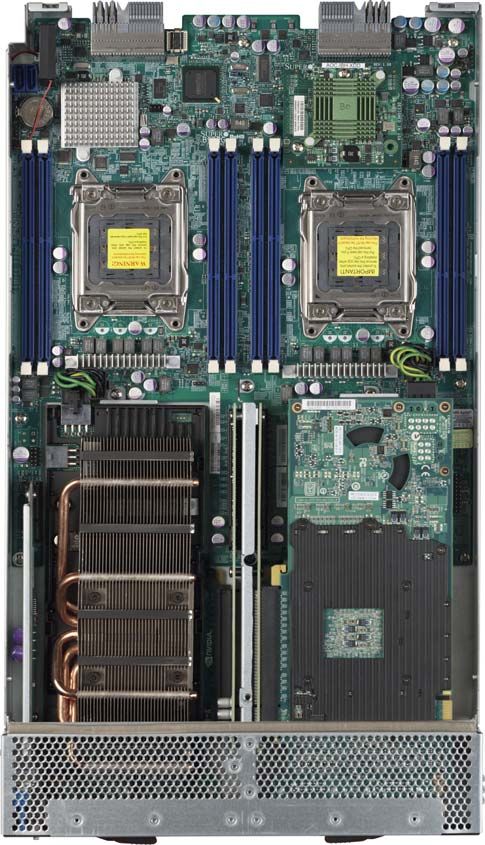
Chapter 4 Blade Module Features .............................................. 4-1
4-1 Control Panel ..................................................................................... 4-2
Power Button .......................................................................................... 4-3
KVM Button............................................................................................. 4-3
LED Indicators ........................................................................................ 4-3
KVM Connector....................................................................................... 4-3
4-2 Mainboard........................................................................................... 4-4
Jumpers .................................................................................................. 4-6
CMOS Clear............................................................................................ 4-6
USB Port Connector ............................................................................... 4-6
4-3 Blade Unit Components ................................................................... 4-7
Memory Support ..................................................................................... 4-8
Hard Disk Drives ..................................................................................... 4-8
Chapter 5 BIOS ....................................................................................... 5-1
5-1 Introduction......................................................................................... 5-1
System BIOS .......................................................................................... 5-1
How To Change the Configuration Data ................................................. 5-1
Starting the Setup Utility.......................................................................... 5-1
5-2 BIOS Updates .................................................................................... 5-2
Flashing BIOS......................................................................................... 5-2
5-3 Running Setup ................................................................................... 5-3
5-4 Main BIOS Setup............................................................................... 5-4
5-5 Advanced Setup ................................................................................ 5-5
5-6 Event Logs Setup ............................................................................ 5-14
5-7 IPMI Setup ........................................................................................ 5-15
5-8 Boot ................................................................................................... 5-16
5-9 Security ............................................................................................. 5-16
5-10 Save & Exit..................................................................................... 5-17
vi:
Appendix A AMI UEFI BIOS POST Codes..............................A-1
A-1 Checkpoint Ranges ..........................................................................A-1
A-2 Standard Checkpoints ......................................................................A-2
A-3 OEM-Reserved Checkpoint Ranges .............................................A-9
viiSBI-7127RG GPU Blade Module User’s Manual
Notes
viiiChapter 1
Introduction
1-1 Overview
The SBI-7127RG GPU blade module is a compact self-contained server that connects
into a pre-cabled enclosure that provides power, cooling, management and networking
functions. One enclosure for the SBI-7127RG GPU blade module can hold ten blade
units.
In this manual, “blade system” refers to the entire system (including the enclosure and
blades units), “blade” or “blade unit” refers to a single blade module and “blade
enclosure” is the chassis that the blades, power supplies and modules are housed in.
Please refer to our web site for information on operating systems that have been
certified for use with the SuperBlade (www.supermicro.com/products/superblade/).
Note: A complete list of safety warnings is provided on the Supermicro web site at
http://www.supermicro.com/about/policies/safety_information.cfm.
1-2 Product Checklist of Typical Components
Your blade module ships with its mainboard already installed in its chassis. Memory,
hard disk drives and the CPU must all be installed by the user after shipment. See
Chapter 3: "Setup and Installation" on page 3-1 for details on installation of these
components.
Aside from the blade module unit itself, the following optional Mezzanine add-on cards
(with Infiniband Switch) may be ordered for your blade module:
• AOC-XEH-iN2
• AOC-IBH-XDD
• AOC-IBH-XQD
• AOC-IBH-XQS
• AOC-IBH-XDS
See the Supermicro website and the SuperBlade Network Modules User’s Manual on
your SuperBlade system’s CD-ROM for more details on these add-on cards.
1-1SBI-7127RG GPU Blade Module User’s Manual
1-3 Blade Module Features
Table 1-1 lists the main features of the SBI-7127RG GPU blade module. See the
proceeding section for components typically included in a blade system and other
optional components. Specific details on the SBI-7127RG GPU blade module is found in
Chapter 4: " Blade Module Features" on page 4-1.
Table 1-1. SBI-7427RG Blade Specification Features
B9DRG (proprietary form factor)
Mainboard
Chassis Dimensions (HxWxD): 11.32” x 1.67” x 18.9”
Single or dual Intel™ Xeon®E5-2600 series 2011-pin (LGA 2011 Socket R)
Processors processors. Please refer to our web site for a complete listing of supported
processors.
FSB Speed QPI up to 8.0 GT/s bus speed
Chipset Intel C602
Graphics Controller Nuvoton WPCM450 BMC with graphic controller
BIOS 128 MB SPI Flash EEPROM with AMI® BIOS
Supports up to 256 GB of RDIMM and 64 GB of UDIMM DDR3 1600/1333/
Memory Capacity
1066 MHz speed SDRAM in eight (8) 240-pin DIMM sockets
Expansion Slots Two (2) PCI-E 3.0 x16 expansion slots
Processors
The SBI-7127RG GPU blade module supports up to dual Intel Xeon E5-2600 series
2011-pin (LGA 2011 Socket R) processors.
Refer to the Supermicro web site for a complete listing of supported processors (http://
www.supermicro.com/products/superblade). Please note that you will need to check the
detailed specifications of a particular blade module for a list of the CPUs it supports.
Details on installation of the processor into the SBI-7127RG GPU blade module are
found in Chapter 3: "Setup and Installation" on page 3-1.
1-2Chapter 1: Introduction
Memory
The SBI-7127RG GPU blade module has eight (8) 240-pin DIMM sockets that can
support up to 256 GB of DDR3 1600/1333/1066 MHz speed SDRAM. Both interleaved
and non-interleaved memory are supported, so you may populate any number of DIMM
slots.
Please refer to the Supermicro web site for a list of supported memory
(www.supermicro.com/products/superblade). The detailed specifications for a blade
module will contain a link to a list of recommended memory sizes and manufacturers.
Details on installation of memory modules into the SBI-7127RG GPU blade module are
found in Chapter 3: "Setup and Installation" on page 3-1.
Storage
The SBI-7427RG GPU blade module does not contain any hard disk drives or drive
carriers. The SBI-7127RG blade module however does include a SATA port for an
optional SATA DOM module which you may use instead as a storage device for files or
an operating system.
Density
A maximum of ten blade modules may be installed into a single blade enclosure. Each
blade enclosure is a 7U form factor, so a standard 42U rack may accommodate up to six
enclosures with 60 blade modules, or the equivalent of 60 1U servers. With the inclusion
of six CMM modules, twelve Gigabit Ethernet switches and six InfiniBand switches, this
would occupy up to 84U space in a conventional 1U server configuration.
Figure 1-1 displays a view of a full rack with six blade enclosures in it, each with ten
blades to an enclosure.
1-3SBI-7127RG GPU Blade Module User’s Manual
Figure 1-1. Full Rack of Blade Enclosures and Blade Servers
1-4Chapter 1: Introduction
1-4 Contacting Supermicro
Headquarters
Address: Super Micro Computer, Inc.
980 Rock Ave.
San Jose, CA 95131 U.S.A.
Tel: +1 (408) 503-8000
Fax: +1 (408) 503-8008
marketing@supermicro.com (General Information)
Email:
support@supermicro.com (Technical Support)
Web Site: www.supermicro.com
Europe
Address: Super Micro Computer B.V.
Het Sterrenbeeld 28, 5215 ML
‘s-Hertogenbosch, The Netherlands
Tel: +31 (0) 73-6400390
Fax: +31 (0) 73-6416525
sales@supermicro.nl (General Information)
Email: support@supermicro.nl (Technical Support)
rma@supermicro.nl (Customer Support)
Asia-Pacific
Address: Super Micro Computer, Inc.
4F, No. 232-1, Liancheng Rd.
Chung-Ho 235, Taipei County
Taiwan, R.O.C.
Tel: +886-(2) 8226-3990
Fax: +886-(2) 8226-3991
Web Site: www.supermicro.com.tw
Technical Support:
Email: support@supermicro.com.tw
Tel: +886-(2) 8226-5990
1-5SBI-7127RG GPU Blade Module User’s Manual
Notes
1-6Chapter 2
Standardized Warning Statements
2-1 About Standardized Warning Statements
The following statements are industry standard warnings, provided to warn the user of
situations which have the potential for bodily injury. Should you have questions or
experience difficulty, contact Supermicro's Technical Support department for assistance.
Only certified technicians should attempt to install or configure components.
Read this appendix in its entirety before installing or configuring components in the
Supermicro chassis
These warnings may also be found on our web site at http://
www.supermicro.com/about/policies/safety_information.cfm.
Warning Definition
Warning!
This warning symbol means danger. You are in a situation that could cause
bodily injury. Before you work on any equipment, be aware of the hazards
involved with electrical circuitry and be familiar with standard practices for preventing
accidents.
此警告符号代表危险。
您正处于可能受到严重伤害的工作环境中。在您使用设备开始工作之前,必须充分意识到
触电的危险,并熟练掌握防止事故发生的标准工作程序。请根据每项警告结尾的声明号码
找到此设备的安全性警告说明的翻译文本。
此警告符號代表危險。
您正處於可能身體可能會受損傷的工作環境中。在您使用任何設備之前,請注意觸電的危
險,並且要熟悉預防事故發生的標準工作程序。請依照每一注意事項後的號碼找到相關的
翻譯說明內容。
2-1SBI-7127RG GPU Blade Module User’s Manual
Warnung
WICHTIGE SICHERHEITSHINWEISE
Dieses Warnsymbol bedeutet Gefahr. Sie befinden sich in einer Situation, die zu
Verletzungen führen kann. Machen Sie sich vor der Arbeit mit Geräten mit den Gefahren
elektrischer Schaltungen und den üblichen Verfahren zur Vorbeugung vor Unfällen
vertraut. Suchen Sie mit der am Ende jeder Warnung angegebenen
Anweisungsnummer nach der jeweiligen Übersetzung in den übersetzten
Sicherheitshinweisen, die zusammen mit diesem Gerät ausgeliefert wurden.
BEWAHREN SIE DIESE HINWEISE GUT AUF.
INSTRUCCIONES IMPORTANTES DE SEGURIDAD
Este símbolo de aviso indica peligro. Existe riesgo para su integridad física. Antes de
manipular cualquier equipo, considere los riesgos de la corriente eléctrica y
familiarícese con los procedimientos estándar de prevención de accidentes. Al final de
cada advertencia encontrará el número que le ayudará a encontrar el texto traducido en
el apartado de traducciones que acompaña a este dispositivo.
GUARDE ESTAS INSTRUCCIONES.
IMPORTANTES INFORMATIONS DE SÉCURITÉ
Ce symbole d'avertissement indique un danger. Vous vous trouvez dans une situation
pouvant entraîner des blessures ou des dommages corporels. Avant de travailler sur un
équipement, soyez conscient des dangers liés aux circuits électriques et
familiarisez-vous avec les procédures couramment utilisées pour éviter les accidents.
Pour prendre connaissance des traductions des avertissements figurant dans les
consignes de sécurité traduites qui accompagnent cet appareil, référez-vous au numéro
de l'instruction situé à la fin de chaque avertissement.
CONSERVEZ CES INFORMATIONS.
תקנון הצהרות אזהרה
על מנת להזהיר את המשתמש מפני חבלה,הצהרות הבאות הן אזהרות על פי תקני התעשייה
יש ליצור קשר עם מחלקת תמיכה, במידה ויש שאלות או היתקלות בבעיה כלשהי.פיזית אפשרית
. טכנאים מוסמכים בלבד רשאים להתקין או להגדיר את הרכיבים.טכנית של סופרמיקרו
.יש לקרוא את הנספח במלואו לפני התקנת או הגדרת הרכיבים במארזי סופרמיקרו
. ﺗﺤﺬﻳﺮ!ﻫﺬﺍ ﺍﻟﺮﻣﺰ ﻳﻌﻨﻲ ﺧﻄﺮ ﺍﻧﻚ ﻓﻲ ﺣﺎﻟﺔ ﻳﻤﻜﻦ ﺃﻥ ﺗﺘﺴﺒﺐ ﻓﻲ ﺍﺻﺎﺑﺔ ﺟﺴﺪﻳﺔ
ﻛﻦ ﻋﻠﻰ ﻋﻠﻢ ﺑﺎﻟﻤﺨﺎﻁﺮ ﺍﻟﻨﺎﺟﻤﺔ ﻋﻦ ﺍﻟﺪﻭﺍﺋﺮ،ﻗﺒﻞ ﺃﻥ ﺗﻌﻤﻞ ﻋﻠﻰ ﺃﻱ ﻣﻌﺪﺍﺕ
ﺍﻟﻜﻬﺮﺑﺎﺋﻴﺔ
ﻭﻛﻦ ﻋﻠﻰ ﺩﺭﺍﻳﺔ ﺑﺎﻟﻤﻤﺎﺭﺳﺎﺕ ﺍﻟﻮﻗﺎﺋﻴﺔ ﻟﻤﻨﻊ ﻭﻗﻮﻉ ﺃﻱ ﺣﻮﺍﺩﺙ
ﺍﺳﺘﺨﺪﻡ ﺭﻗﻢ ﺍﻟﺒﻴﺎﻥ ﺍﻟﻤﻨﺼﻮﺹ ﻓﻲ ﻧﻬﺎﻳﺔ ﻛﻞ ﺗﺤﺬﻳﺮ ﻟﻠﻌﺜﻮﺭ ﺗﺮﺟﻤﺘﻬﺎ
2-2Chapter 2: Standardized Warning Statements
BELANGRIJKE VEILIGHEIDSINSTRUCTIES
Dit waarschuwings symbool betekent gevaar. U verkeert in een situatie die lichamelijk
letsel kan veroorzaken. Voordat u aan enige apparatuur gaat werken, dient u zich
bewust te zijn van de bij een elektrische installatie betrokken risico's en dient u op de
hoogte te zijn van de standaard procedures om ongelukken te voorkomen. Gebruik de
nummers aan het eind van elke waarschuwing om deze te herleiden naar de
desbetreffende locatie.
BEWAAR DEZE INSTRUCTIES
Installation Instructions
Warning!
Read the installation instructions before connecting the system to the power
source.
警告
将此系统连接电源前 , 请先阅读安装说明。
警告
將系統與電源連接前,請先閱讀安裝說明。
Warnung
Vor dem Anschließen des Systems an die Stromquelle die Installationsanweisungen
lesen.
¡Advertencia!
Lea las instrucciones de instalación antes de conectar el sistema a la red de
alimentación.
Attention
Avant de brancher le système sur la source d'alimentation, consulter les directives
d'installation.
2-3SBI-7127RG GPU Blade Module User’s Manual
.יש לקרוא את הוראות התקנה לפני חיבור המערכת למקור מתח
ﺍﻗﺮ ﺇﺭﺷﺎﺩﺍﺕ ﺍﻟﺘﺮﻛﻴﺐ ﻗﺒﻞ ﺗﻮﺻﻴﻞ ﺍﻟﻨﻈﺎﻡ ﺇﻟﻰ ﻣﺼﺪﺭ ﻟﻠﻄﺎﻗﺔ
Waarschuwing
Raadpleeg de installatie-instructies voordat u het systeem op de voedingsbron aansluit.
Circuit Breaker
Warning!
This product relies on the building's installation for short-circuit (overcurrent)
protection. Ensure that the protective device is rated not greater than: 250 V,
20 A.
警告
此产品的短路 ( 过载电流 ) 保护由建筑物的供电系统提供 , 确保短路保护设备的额定电流
不大于 250V,20A。
警告
此產品的短路 ( 過載電流 ) 保護由建築物的供電系統提供 , 確保短路保護設備的額定電
流不大於 250V,20A。
Warnung
Dieses Produkt ist darauf angewiesen, dass im Gebäude ein Kurzschluss- bzw.
Überstromschutz installiert ist. Stellen Sie sicher, dass der Nennwert der
Schutzvorrichtung nicht mehr als: 250 V, 20 A beträgt.
¡Advertencia!
Este equipo utiliza el sistema de protección contra cortocircuitos (o sobrecorrientes) del
edificio. Asegúrese de que el dispositivo de protección no sea superior a: 250 V, 20 A.
Attention
Pour ce qui est de la protection contre les courts-circuits (surtension), ce produit dépend
de l'installation électrique du local. Vérifiez que le courant nominal du dispositif de
protection n'est pas supérieur à :250 V, 20 A.
יש לוודא כי.מוצר זה מסתמך על הגנה המותקנת במבנים למניעת קצר חשמלי
250 V, 20 A-המכשיר המגן מפני הקצר החשמלי הוא לא יותר מ
2-4Chapter 2: Standardized Warning Statements
ﻫﺬﺍ ﺍﻟﻤﻨﺘﺞ ﻳﻌﺘﻤﺪ ﻋﻠﻰ ﻣﻌﺪﺍﺕ ﺍﻟﺤﻤﺎﻳﺔ ﻣﻦ ﺍﻟﺪﻭﺍﺋﺮﺍﻟﻘﺼﻴﺮﺓ ﺍﻟﺘﻲ ﺗﻢ ﺗﺜﺒﻴﺘﻬﺎ ﻓﻲ
ﺍﻟﻤﺒﻨﻰ
20A, 250V :ﺗﺄﻛﺪ ﻣﻦ ﺃﻥ ﺗﻘﻴﻴﻢ ﺍﻟﺠﻬﺎﺯ ﺍﻟﻮﻗﺎﺋﻲ ﻟﻴﺲ ﺃﻛﺜﺮ ﻣﻦ
Waarschuwing
Dit product is afhankelijk van de kortsluitbeveiliging (overspanning) van uw electrische
installatie. Controleer of het beveiligde aparaat niet groter gedimensioneerd is dan
220V, 20A.
Power Disconnection Warning
Warning!
The system must be disconnected from all sources of power and the power
cord removed from the power supply module(s) before accessing the chassis
interior to install or remove system components.
警告
在你打开机箱并安装或移除内部器件前 , 必须将系统完全断电 , 并移除电源线。
警告
在您打開機殼安裝或移除內部元件前,必須將系統完全斷電,並移除電源線。
Warnung
Das System muss von allen Quellen der Energie und vom Netzanschlusskabel getrennt
sein, das von den Spg.Versorgungsteilmodulen entfernt wird, bevor es auf den
Chassisinnenraum zurückgreift, um Systemsbestandteile anzubringen oder zu
entfernen.
2-5SBI-7127RG GPU Blade Module User’s Manual
¡Advertencia!
El sistema debe ser disconnected de todas las fuentes de energía y del cable eléctrico
quitado de los módulos de fuente de alimentación antes de tener acceso el interior del
chasis para instalar o para quitar componentes de sistema.
Attention
Le système doit être débranché de toutes les sources de puissance ainsi que de son
cordon d'alimentation secteur avant d'accéder à l'intérieur du chassis pour installer ou
enlever des composants de systéme.
אזהרה מפני ניתוק חשמלי
!אזהרה
יש לנתק את המערכת מכל מקורות החשמל ויש להסיר את כבל החשמלי מהספק
.לפני גישה לחלק הפנימי של המארז לצורך התקנת או הסרת רכיבים
ﻳﺠﺐ ﻓﺼﻞ ﺍﻟﻨﻈﺎﻡ ﻣﻦ ﺟﻤﻴﻊ ﻣﺼﺎﺩﺭ ﺍﻟﻄﺎﻗﺔ ﻭﺇﺯﺍﻟﺔ ﺳﻠﻚ ﺍﻟﻜﻬﺮﺑﺎء ﻣﻦ ﻭﺣﺪﺓ ﺍﻣﺪﺍﺩ
ﺍﻟﻄﺎﻗﺔ ﻗﺒﻞ
ﺍﻟﻮﺻﻮﻝ ﺇﻟﻰ ﺍﻟﻤﻨﺎﻁﻖ ﺍﻟﺪﺍﺧﻠﻴﺔ ﻟﻠﻬﻴﻜﻞ ﻟﺘﺜﺒﻴﺖ ﺃﻭ ﺇﺯﺍﻟﺔ ﻣﻜﻮﻧﺎﺕ ﺍﻟﺠﻬﺎﺯ
Waarschuwing
Voordat u toegang neemt tot het binnenwerk van de behuizing voor het installeren of
verwijderen van systeem onderdelen, dient u alle spanningsbronnen en alle
stroomkabels aangesloten op de voeding(en) van de behuizing te verwijderen.
Equipment Installation
Warning!
Only trained and qualified personnel should be allowed to install, replace, or
service this equipment.
警告
只有经过培训且具有资格的人员才能进行此设备的安装、更换和维修。
警告
只有經過受訓且具資格人員才可安裝、更換與維修此設備。
2-6Chapter 2: Standardized Warning Statements
Warnung
Das Installieren, Ersetzen oder Bedienen dieser Ausrüstung sollte nur geschultem,
qualifiziertem Personal gestattet werden.
¡Advertencia!
Solamente el personal calificado debe instalar, reemplazar o utilizar este equipo.
Attention
Il est vivement recommandé de confier l'installation, le remplacement et la maintenance
de ces équipements à des personnels qualifiés et expérimentés.
!אזהרה
. להחליף את הציוד או לתת שירות עבור הציוד,צוות מוסמך בלבד רשאי להתקין
ﻳﺠﺐ ﺃﻥ ﻳﺴﻤﺢ ﻓﻘﻂ ﻟﻠﻤﻮﻅﻔﻴﻦ ﺍﻟﻤﺆﻫﻠﻴﻦ ﻭﺍﻟﻤﺪﺭﺑﻴﻦ ﻟﺘﺮﻛﻴﺐ ﻭﺍﺳﺘﺒﺪﺍﻝ ﺃﻭ ﺧﺪﻣﺔ ﻫﺬﺍ ﺍﻟﺠﻬﺎﺯ
Waarschuwing
Deze apparatuur mag alleen worden geïnstalleerd, vervangen of hersteld door
geschoold en gekwalificeerd personeel.
Restricted Area
Warning!
This unit is intended for installation in restricted access areas. A restricted
access area can be accessed only through the use of a special tool, lock and
key, or other means of security. (This warning does not apply to workstations).
警告
此部件应安装在限制进出的场所,限制进出的场所指只能通过使用特殊工具、锁和钥匙或
其它安全手段进出的场所。
警告
此裝置僅限安裝於進出管制區域,進出管制區域係指僅能以特殊工具、鎖頭及鑰匙或其
他安全方式才能進入的區域。
2-7SBI-7127RG GPU Blade Module User’s Manual
Warnung
Diese Einheit ist zur Installation in Bereichen mit beschränktem Zutritt vorgesehen. Der
Zutritt zu derartigen Bereichen ist nur mit einem Spezialwerkzeug, Schloss und
Schlüssel oder einer sonstigen Sicherheitsvorkehrung möglich.
¡Advertencia!
Esta unidad ha sido diseñada para instalación en áreas de acceso restringido. Sólo
puede obtenerse acceso a una de estas áreas mediante la utilización de una
herramienta especial, cerradura con llave u otro medio de seguridad.
Attention
Cet appareil doit être installée dans des zones d'accès réservés. L'accès à une zone
d'accès réservé n'est possible qu'en utilisant un outil spécial, un mécanisme de
verrouillage et une clé, ou tout autre moyen de sécurité.
אזור עם גישה מוגבלת
!אזהרה
הגישה ניתנת בעזרת.יש להתקין את היחידה באזורים שיש בהם הגבלת גישה
.(' מנעול וכד,כלי אבטחה בלבד )מפתח
. ﺗﻢ ﺗﺨﺼﻴﺺ ﻫﺬﻩ ﺍﻟﻮﺣﺪﺓ ﻟﺘﺮﻛﻴﺒﻬﺎ ﻓﻲ ﻣﻨﺎﻁﻖ ﻣﺤﻈﻮﺭﺓ
،ﻳﻤﻜﻦ ﺍﻟﻮﺻﻮﻝ ﺇﻟﻰ ﻣﻨﻄﻘﺔ ﻣﺤﻈﻮﺭﺓ ﻓﻘﻂ ﻣﻦ ﺧﻼﻝ ﺍﺳﺘﺨﺪﺍﻡ ﺃﺩﺍﺓ ﺧﺎﺻﺔ
ﻗﻔﻞ ﻭﻣﻔﺘﺎﺡ ﺃﻭ ﺃﻱ ﻭﺳﻴﻠﺔ ﺃﺧﺮﻯ ﻟﻼﻷﻣﺎﻥ
Waarschuwing
Dit apparaat is bedoeld voor installatie in gebieden met een beperkte toegang. Toegang
tot dergelijke gebieden kunnen alleen verkregen worden door gebruik te maken van
speciaal gereedschap, slot en sleutel of andere veiligheidsmaatregelen.
2-8Chapter 2: Standardized Warning Statements
Battery Handling
Warning!
There is the danger of explosion if the battery is replaced incorrectly. Replace
the battery only with the same or equivalent type recommended by the
manufacturer. Dispose of used batteries according to the manufacturer's instructions.
警告
电池更换不当会有爆炸危险。请只使用同类电池或制造商推荐的功能相当的电池更换原有
电池。请按制造商的说明处理废旧电池。
警告
電池更換不當會有爆炸危險。請使用製造商建議之相同或功能相當的電池更換原有電
池。請按照製造商的說明指示處理廢棄舊電池。
Warnung
Bei Einsetzen einer falschen Batterie besteht Explosionsgefahr. Ersetzen Sie die
Batterie nur durch den gleichen oder vom Hersteller empfohlenen Batterietyp.
Entsorgen Sie die benutzten Batterien nach den Anweisungen des Herstellers.
Attention
Danger d'explosion si la pile n'est pas remplacée correctement. Ne la remplacer que par
une pile de type semblable ou équivalent, recommandée par le fabricant. Jeter les piles
usagées conformément aux instructions du fabricant.
¡Advertencia!
Existe peligro de explosión si la batería se reemplaza de manera incorrecta.
Reemplazar la batería exclusivamente con el mismo tipo o el equivalente recomendado
por el fabricante. Desechar las baterías gastadas según las instrucciones del fabricante.
!אזהרה
יש להחליף.קיימת סכנת פיצוץ של הסוללה במידה והוחלפה בדרך לא תקינה
.את הסוללה בסוג התואם מחברת יצרן מומלצת
.סילוק הסוללות המשומשות יש לבצע לפי הוראות היצרן
ﻫﻨﺎﻙ ﺧﻄﺮ ﻣﻦ ﺍﻧﻔﺠﺎﺭ ﻓﻲ ﺣﺎﻟﺔ ﺍﺳﺘﺒﺪﺍﻝ ﺍﻟﺒﻄﺎﺭﻳﺔ ﺑﻄﺮﻳﻘﺔ ﻏﻴﺮ ﺻﺤﻴﺤﺔ ﻓﻌﻠﻴﻚ
ﺍﺳﺘﺒﺪﺍﻝ ﺍﻟﺒﻄﺎﺭﻳﺔ
ﻓﻘﻂ ﺑﻨﻔﺲ ﺍﻟﻨﻮﻉ ﺃﻭ ﻣﺎ ﻳﻌﺎﺩﻟﻬﺎ ﻛﻤﺎ ﺃﻭﺻﺖ ﺑﻪ ﺍﻟﺸﺮﻛﺔ ﺍﻟﻤﺼﻨﻌﺔ
ﺗﺨﻠﺺ ﻣﻦ ﺍﻟﺒﻄﺎﺭﻳﺎﺕ ﺍﻟﻤﺴﺘﻌﻤﻠﺔ ﻭﻓﻘﺎ ﻟﺘﻌﻠﻴﻤﺎﺕ ﺍﻟﺸﺮﻛﺔ ﺍﻟﺼﺎﻧﻌﺔ
2-9SBI-7127RG GPU Blade Module User’s Manual
Waarschuwing
Er is ontploffingsgevaar indien de batterij verkeerd vervangen wordt. Vervang de batterij
slechts met hetzelfde of een equivalent type die door de fabrikant aanbevolen wordt.
Gebruikte batterijen dienen overeenkomstig fabrieksvoorschriften afgevoerd te worden.
Redundant Power Supplies
Warning!
This unit might have more than one power supply connection. All connections
must be removed to de-energize the unit.
警告
此部件连接的电源可能不止一个,必须将所有电源断开才能停止给该部件供电。
警告
此裝置連接的電源可能不只一個,必須切斷所有電源才能停止對該裝置的供電。
Warnung
Dieses Gerät kann mehr als eine Stromzufuhr haben. Um sicherzustellen, dass der
Einheit kein trom zugeführt wird, müssen alle Verbindungen entfernt werden.
¡Advertencia!
Puede que esta unidad tenga más de una conexión para fuentes de alimentación. Para
cortar por completo el suministro de energía, deben desconectarse todas las
conexiones.
Attention
Cette unité peut avoir plus d'une connexion d'alimentation. Pour supprimer toute tension
et tout courant électrique de l'unité, toutes les connexions d'alimentation doivent être
débranchées.
אם קיים יותר מספק אחד
!אזהרה
יש להסיר את כל החיבורים על מנת לרוקן.ליחדה יש יותר מחיבור אחד של ספק
.את היחידה
2-10Chapter 2: Standardized Warning Statements
.ﻗﺪ ﻳﻜﻮﻥ ﻟﻬﺬﺍ ﺍﻟﺠﻬﺎﺯ ﻋﺪﺓ ﺍﺗﺼﺎﻻﺕ ﺑﻮﺣﺪﺍﺕ ﺍﻣﺪﺍﺩ ﺍﻟﻄﺎﻗﺔ
ﻳﺠﺐ ﺇﺯﺍﻟﺔ ﻛﺎﻓﺔ ﺍﻻﺗﺼﺎﻻﺕ ﻟﻌﺰﻝ ﺍﻟﻮﺣﺪﺓ ﻋﻦ ﺍﻟﻜﻬﺮﺑﺎء
Waarschuwing
Deze eenheid kan meer dan één stroomtoevoeraansluiting bevatten. Alle aansluitingen
dienen verwijderd te worden om het apparaat stroomloos te maken
Backplane Voltage
Warning!
Hazardous voltage or energy is present on the backplane when the system is
operating. Use caution when servicing.
警告
当系统正在进行时,背板上有很危险的电压或能量,进行维修时务必小心。
警告
當系統正在進行時,背板上有危險的電壓或能量,進行維修時務必小心。
Warnung
Wenn das System in Betrieb ist, treten auf der Rückwandplatine gefährliche
Spannungen oder Energien auf. Vorsicht bei der Wartung.
¡Advertencia!
Cuando el sistema está en funcionamiento, el voltaje del plano trasero es peligroso.
Tenga cuidado cuando lo revise.
Attention
Lorsque le système est en fonctionnement, des tensions électriques circulent sur le fond
de panier. Prendre des précautions lors de la maintenance.
מתח בפנל האחורי
!אזהרה
יש להיזהר במהלך.קיימת סכנת מתח בפנל האחורי בזמן תפעול המערכת
.העבודה
2-11SBI-7127RG GPU Blade Module User’s Manual
ﻫﻨﺎﻙ ﺧﻄﺮ ﻣﻦ ﺍﻟﺘﻴﺎﺭ ﺍﻟﻜﻬﺮﺑﺎﺋﻲ ﺃﻭﺍﻟﻄﺎﻗﺔ ﺍﻟﻤﻮﺟﻮﺩﺓ ﻋﻠﻰ ﺍﻟﻠﻮﺣﺔ
ﻋﻨﺪﻣﺎ ﻳﻜﻮﻥ ﺍﻟﻨﻈﺎﻡ ﻳﻌﻤﻞ ﻛﻦ ﺣﺬﺭﺍ ﻋﻨﺪ ﺧﺪﻣﺔ ﻫﺬﺍ ﺍﻟﺠﻬﺎﺯ
Waarschuwing
Een gevaarlijke spanning of energie is aanwezig op de backplane wanneer het systeem
in gebruik is. Voorzichtigheid is geboden tijdens het onderhoud.
Comply with Local and National Electrical Codes
Warning!
Installation of the equipment must comply with local and national electrical
codes.
警告
设备安装必须符合本地与本国电气法规。
警告
設備安裝必須符合本地與本國電氣法規。
Warnung
Die Installation der Geräte muss den Sicherheitsstandards entsprechen.
¡Advertencia!
La instalacion del equipo debe cumplir con las normas de electricidad locales y
nacionales.
Attention
L'équipement doit être installé conformément aux normes électriques nationales et
locales.
תיאום חוקי החשמל הארצי
!אזהרה
.התקנת הציוד חייבת להיות תואמת לחוקי החשמל המקומיים והארציים
ﺗﺮﻛﻴﺐ ﺍﻟﻤﻌﺪﺍﺕ ﺍﻟﻜﻬﺮﺑﺎﺋﻴﺔ ﻳﺠﺐ ﺃﻥ ﻳﻤﺘﺜﻞ ﻟﻠﻘﻮﺍﻧﻴﻦ ﺍﻟﻤﺤﻠﻴﺔ ﻭﺍﻟﻮﻁﻨﻴﺔ ﺍﻟﻤﺘﻌﻠﻘﺔ
ﺑﺎﻟﻜﻬﺮﺑﺎء
2-12Chapter 2: Standardized Warning Statements
Waarschuwing
Bij installatie van de apparatuur moet worden voldaan aan de lokale en nationale
elektriciteitsvoorschriften.
Product Disposal
Warning!
Ultimate disposal of this product should be handled according to all national
laws and regulations.
警告
本产品的废弃处理应根据所有国家的法律和规章进行。
警告
本產品的廢棄處理應根據所有國家的法律和規章進行。
Warnung
Die Entsorgung dieses Produkts sollte gemäß allen Bestimmungen und Gesetzen des
Landes erfolgen.
¡Advertencia!
Al deshacerse por completo de este producto debe seguir todas las leyes y reglamentos
nacionales.
Attention
La mise au rebut ou le recyclage de ce produit sont généralement soumis à des lois et/
ou directives de respect de l'environnement. Renseignez-vous auprès de l'organisme
compétent.
סילוק המוצר
!אזהרה
.סילוק סופי של מוצר זה חייב להיות בהתאם להנחיות וחוקי המדינה
ﻋﻨﺪ ﺍﻟﺘﺨﻠﺺ ﺍﻟﻨﻬﺎﺋﻲ ﻣﻦ ﻫﺬﺍ ﺍﻟﻤﻨﺘﺞ ﻳﻨﺒﻐﻲ ﺍﻟﺘﻌﺎﻣﻞ ﻣﻌﻪ ﻭﻓﻘﺎ ﻟﺠﻤﻴﻊ ﺍﻟﻘﻮﺍﻧﻴﻦ ﻭﺍﻟﻠﻮﺍﺋﺢ ﺍﻟﻮﻁﻨﻴﺔ
2-13SBI-7127RG GPU Blade Module User’s Manual
Waarschuwing
De uiteindelijke verwijdering van dit product dient te geschieden in overeenstemming
met alle nationale wetten en reglementen.
Hot Swap Fan Warning
Warning!
The fans might still be turning when you remove the fan assembly from the
chassis. Keep fingers, screwdrivers, and other objects away from the
openings in the fan assembly's housing.
警告
当您从机架移除风扇装置,风扇可能仍在转动。小心不要将手指、螺丝起子和其他物品太
靠近风扇
警告
當您從機架移除風扇裝置,風扇可能仍在轉動。小心不要將手指、螺絲起子和其他物品
太靠近風扇。
Warnung
Die Lüfter drehen sich u. U. noch, wenn die Lüfterbaugruppe aus dem Chassis
genommen wird. Halten Sie Finger, Schraubendreher und andere Gegenstände von
den Öffnungen des Lüftergehäuses entfernt.
¡Advertencia!
Los ventiladores podran dar vuelta cuando usted quite ell montaje del ventilador del
chasis. Mandtenga los dedos, los destornilladores y todos los objetos lejos de las
aberturas del ventilador
Attention
Il est possible que les ventilateurs soient toujours en rotation lorsque vous retirerez le
bloc ventilateur du châssis. Prenez garde à ce que doigts, tournevis et autres objets
soient éloignés du logement du bloc ventilateur.
!אזהרה
יש. יתכן והמאווררים עדיין עובדים,כאשר מסירים את חלקי המאוורר מהמארז
להרחיק למרחק בטוח את האצבעות וכלי עבודה שונים מהפתחים בתוך המאוורר
2-14Chapter 2: Standardized Warning Statements
ﻣﻦ ﺍﻟﻤﻤﻜﻦ ﺃﻥ ﺍﻟﻤﺮﺍﻭﺡ ﻻ ﺗﺰﺍﻝ ﺗﺪﻭﺭﻋﻨﺪ ﺇﺯﺍﻟﺔ ﻛﺘﻠﺔ ﺍﻟﻤﺮﻭﺣﺔ ﻣﻦ ﺍﻟﻬﻴﻜﻞ ﻳﺠﺐ ﺇﺑﻘﺎء
ﺍﻷﺻﺎﺑﻊ ﻭﻣﻔﻜﺎﺕ ﺍﻟﺒﺮﺍﻏﻲ
.ﻭﻏﻴﺮﻫﺎ ﻣﻦ ﺍﻷﺷﻴﺎء ﺑﻌﻴﺪﺍ ﻋﻦ ﺍﻟﻔﺘﺤﺎﺕ ﻓﻲ ﻛﺘﻠﺔ ﺍﻟﻤﺮﻭﺣﺔ
Waarschuwing
Het is mogelijk dat de ventilator nog draait tijdens het verwijderen van het
ventilatorsamenstel uit het chassis. Houd uw vingers, schroevendraaiers en eventuele
andere voorwerpen uit de buurt van de openingen in de ventilatorbehuizing.
Power Cable and AC Adapter
Warning!
When installing the product, use the provided or designated connection
cables, power cables and AC adaptors. Using any other cables and adaptors
could cause a malfunction or a fire. Electrical Appliance and Material Safety Law
prohibits the use of UL or CSA -certified cables (that have UL/CSA shown on the code)
for any other electrical devices than products designated by Supermicro only.
警告
安装此产品时,请使用本身提供的或指定的连接线,电源线和电源适配器.使用其它线材或
适配器可能会引起故障或火灾。除了 Supermicro 所指定的产品 , 电气用品和材料安全法
律规定禁止使用未经 UL 或 CSA 认证的线材。( 线材上会显示 UL/CSA 符号 )。
警告
安裝此產品時 , 請使用本身提供的或指定的連接線 , 電源線和電源適配器 . 使用其它線
材或適配器可能會引起故障或火災。除了 Supermicro 所指定的產品 , 電氣用品和材料安
全法律規定禁止使用未經 UL 或 CSA 認證的線材。( 線材上會顯示 UL/CSA 符號 )。
2-15SBI-7127RG GPU Blade Module User’s Manual
Warnung
Bei der Installation des Produkts, die zur Verfügung gestellten oder benannt
Anschlusskabel, Stromkabel und Netzteile. Verwendung anderer Kabel und Adapter
kann zu einer Fehlfunktion oder ein Brand entstehen. Elektrische Geräte und Material
Safety Law verbietet die Verwendung von UL-oder CSA-zertifizierte Kabel, UL oder
CSA auf der Code für alle anderen elektrischen Geräte als Produkte von Supermicro
nur bezeichnet gezeigt haben.
¡Advertencia!
Al instalar el producto, utilice los cables de conexión previstos o designados, los cables
y adaptadores de CA. La utilización de otros cables y adaptadores podría ocasionar un
mal funcionamiento o un incendio. Aparatos Eléctricos y la Ley de Seguridad del
Material prohíbe el uso de UL o CSA cables certificados que tienen UL o CSA se
muestra en el código de otros dispositivos eléctricos que los productos designados por
Supermicro solamente.
Attention
Lors de l'installation du produit, utilisez les bables de connection fournis ou désigné.
L'utilisation d'autres cables et adaptateurs peut provoquer un dysfonctionnement ou un
incendie. Appareils électroménagers et de loi sur la sécurité Matériel interdit l'utilisation
de UL ou CSA câbles certifiés qui ont UL ou CSA indiqué sur le code pour tous les
autres appareils électriques que les produits désignés par Supermicro seulement.
AC חשמליים ומתאמי
!אזהרה
אשרAC ספקים ומתאמים, יש להשתמש בכבלים,כאשר מתקינים את המוצר
שימוש בכל כבל או מתאם אחר יכול לגרום לתקלה או.נועדו וסופקו לשם כך
קיים איסור, על פי חוקי שימוש במכשירי חשמל וחוקי בטיחות.קצר חשמלי
)כשאר מופיע עליהם קוד שלCSA - או בUL -להשתמש בכבלים המוסמכים ב
.( עבור כל מוצר חשמלי אחר שלא צוין על ידי סופרקמיקרו בלבדUL/CSA
ﻭﺍﻟﻜﺎﺑﻼﺕ ﺍﻟﻜﻬﺮﺑﺎﺋﻴﺔ،ﻋﻨﺪ ﺗﺮﻛﻴﺐ ﺍﻟﺠﻬﺎﺯ ﻳﺠﺐ ﺍﺳﺘﺨﺪﺍﻡ ﻛﺎﺑﻼﺕ ﺍﻟﺘﻮﺻﻴﻞ
ﻭﻣﺤﻮﻻﺕ ﺍﻟﺘﻴﺎﺭ ﺍﻟﻤﺘﺮﺩﺩ
. ﺃﻥ ﺍﺳﺘﺨﺪﺍﻡ ﺃﻱ ﻛﺎﺑﻼﺕ ﻭﻣﺤﻮﻻﺕ ﺃﺧﺮﻯ ﻳﺘﺴﺒﺐ ﻓﻲ ﺣﺪﻭﺙ ﻋﻄﻞ ﺃﻭ ﺣﺮﻳﻖ. ﺍﻟﺘﻲ
ﺗﻢ ﺗﻮﻓﻴﺮﻫﺎ ﻟﻚ ﻣﻊ ﺍﻟﻤﻨﺘﺞ
UL ﺃﻭCSA ﺍﻷﺟﻬﺰﺓ ﺍﻟﻜﻬﺮﺑﺎﺋﻴﺔ ﻭﻣﻮﺍﺩ ﻗﺎﻧﻮﻥ ﺍﻟﺴﻼﻣﺔ ﻳﺤﻈﺮ ﺍﺳﺘﺨﺪﺍﻡ ﺍﻟﻜﺎﺑﻼﺕ
ﻣﻌﺘﻤﺪﺓ ﻣﻦ ﻗﺒﻞ
Supermicro ﻷﻱ ﺃﺟﻬﺰﺓ ﻛﻬﺮﺑﺎﺋﻴﺔ ﺃﺧﺮﻯ ﻏﻴﺮ ﺍﻟﻤﻨﺘﺠﺎﺕ ﺍﻟﻤﻌﻴﻨﺔ ﻣﻦ ﻗﺒﻞ
(UL/CSA )ﺍﻟﺘﻲ ﺗﺤﻤﻞ ﻋﻼﻣﺔ
2-16Chapter 2: Standardized Warning Statements
Waarschuwing
Bij het installeren van het product, gebruik de meegeleverde of aangewezen kabels,
stroomkabels en adapters. Het gebruik van andere kabels en adapters kan leiden tot
een storing of een brand. Elektrisch apparaat en veiligheidsinformatiebladen wet
verbiedt het gebruik van UL of CSA gecertificeerde kabels die UL of CSA die op de code
voor andere elektrische apparaten dan de producten die door Supermicro alleen.
2-17SBI-7127RG GPU Blade Module User’s Manual
Notes
2-18Chapter 3: Setup and Installation
Chapter 3
Setup and Installation
3-1 Overview
This chapter covers the setup and installation of the blade module and its components.
3-2 Installing Blade Modules
Up to ten SBI-7127RG GPU blade modules may be installed into a single blade
enclosure (depending upon your enclosure and blade). Blade modules with Windows
and Linux operating systems may be mixed together in the same blade enclosure.
Powering Up a Blade Unit
Each blade unit may be powered on and off independently from the rest of the blades
installed in the same enclosure. A blade unit may be powered up in two ways:
• Press the power button on the blade unit.
• Use IPMIView or the web-browser based management utility to apply power using
either a CMM module, or by the use of the onboard BMC chip in the blade module.
Powering Down a Blade Unit
A blade unit may be powered down in either of the following ways:
• Press the power button on the blade unit.
• Use IPMIView or the web-browser based management utility to power down (if you
have Operator or Admin privileges on the CMM).
• Use IPMItool when connected to the CMM to power down (if you have Operator or
Admin privileges on the CMM).
Removing a Blade Unit from the Enclosure
Although the blade system may continue to run, individual blades should always be
powered down before removing them from the enclosure.
Removing a Blade Unit from the Enclosure
1. Power down the blade unit (see "Powering Down a Blade Unit" above).
2. Squeeze both handles to depress the red sections then pull out both handles
completely and use them to pull the blade unit from the enclosure.
Note: Blade Modules can be Hot-Plugged from the enclosure.
3-1SBI-7127RG GPU Blade Module User’s Manual
Removing/Replacing the Blade Cover
The blade cover must be removed to access the mainboard when you need to install or
remove processors, memory units, the onboard battery and so on.
Removing/Replacing the Blade Cover
1. Remove the blade unit from the enclosure (see "Removing a Blade Unit from the
Enclosure" above).
2. Remove the retaining screw from the top of the blade cover, then depress the two
buttons on the cover while pushing the cover toward the rear of the blade unit.
When it stops, lift the cover off the blade unit.
3. To replace the cover, fit the six grooves in the cover into the studs in the sides of the
blade, then slide the cover toward the front of the blade to lock it into place. Rescrew
the blade cover retaining screw back into place.
Installing a Blade Unit into the Enclosure
Make sure the cover of the blade unit has been replaced first before installing a blade
unit in the enclosure.
Installing a Blade Unit into the Enclosure
1. Slowly push the blade unit into its bay with the handles fully pulled out (see
Figure 3-1).
2. When the blade stops, push the handles back in to their locked position, making
sure the notches in both handles catch the lip of the enclosure (see Figure 3-2).
Note: Blade Modules can be Hot-Plugged into the enclosure.
Warning: Use extreme caution when inserting a blade module into the enclosure.
If the blade's power connector becomes damaged, it can damage pins on other blade
bays that it is inserted into.
Note: The below illustrations in Figure 3-1 and Figure 3-2 demonstrate the removal and
insertion for all Supermicro blade modules. Your blade module or enclosure may appear
different than illustrated but uses the same handles and method of insertion.
3-2Chapter 3: Setup and Installation
Figure 3-1. Inserting a Blade into the Enclosure
Figure 3-2. Locking the Blade into Position
3-3SBI-7127RG GPU Blade Module User’s Manual
3-3 Processor Installation
One or two processors may be installed to the mainboard of each blade unit. See
Chapter 1 for general information on the features of the blade unit and the Supermicro
web site for further details including processor, memory and operating system support.
Warning: This action should only be performed by a trained service technician. Allow
the processor heatsink to cool before removing it.
Removing a Processor
Warning: This action should only be performed by a trained service technician.
Removing a Processor
1. Power down and remove the blade unit from the enclosure (see Section 3-2:
Installing Blade Modules on page 3-1 for details).
2. Remove the cover of the blade unit (see "Removing/Replacing the Blade Cover" on
page 3-2).
3. Loosen the four screws that secure the heatsink to the mainboard.
4. Remove the heatsink by gently rotating it back-and-forth sideways with your fingers
to release it from the processor. Set the heatsink aside and upside-down so that
nothing comes into contact with the thermal grease on its underside.
5. Raise the lever of the processor socket up until the processor is released from the
socket, then lift the silver cover plate and remove the processor.
6. Reapply plastic socket covers to the LGA2011 sockets to prevent pin damage.
Installing a Processor
Warning: When handling the processor package, avoid placing direct pressure on the
label area.
Warning: Always connect the power cord last, and always remove it before adding,
removing or changing any hardware components. Make sure that you install the
processor into the CPU socket before you install the CPU heatsink.
Warning: Important! If you buy a CPU separately, make sure that you use an
Intel-certified multi-directional heatsink only.
Caution: When receiving a server board without a processor pre-installed, make sure
that the plastic CPU socket cap is in place and none of the socket pins are bent;
otherwise, contact your retailer immediately.
Note: Make sure to install the system board into the chassis before you install the CPU
heatsink.
Note: Refer to the Supermicro website for updates on CPU support.
3-4Chapter 3: Setup and Installation
Installing a Processor
1. There are two load levers on the LGA2011 socket. To open the socket cover, first
press and release the load lever labeled 'Open 1st' (Figure 3-3).
Figure 3-3. Open First Load Lever
WA WA
RN R NI
IN NG
G! !
OP OP
EN EN
1st 1st
Press down on Load
Lever labeled 'Open
2. Press the second load lever labeled 'Close 1st' to release the load plate that covers
the CPU socket from its locking position (Figure 3-4).
Figure 3-4. Close First Load Lever
Press down on
Load the Lever
labeled 'Close 1st'
WA WA
R NI R NI
NG NG
! !
OP OP
EN EN
1st 1st
Pull lever away from the socket
3-5SBI-7127RG GPU Blade Module User’s Manual
3. With the lever labeled 'Close 1st' fully retracted, gently push down on the 'Open 1st'
lever to open the load plate. Lift the load plate to open it completely (Figure 3-5).
Figure 3-5. Opening the Load Plate
Gently push down to
pop the load plate
WA WA
RN R NI
IN NG
G! !
OP
EN
1st
4. Using your thumb and the index finger, remove the 'WARNING' plastic cap from the
socket (Figure 3-6).
Figure 3-6. Removing the Warning Plastic Cap
WA
R NIN
G!
3-6Chapter 3: Setup and Installation
5. Use your thumb and index finger to hold the CPU on its edges. Align the CPU keys,
which are semi-circle cutouts, against the socket keys (Figure 3-7).
Figure 3-7. Aligning CPU Keys with Socket Keys
Socket Keys
CPU Keys
6. Once the keys are aligned, carefully lower the CPU straight down into the socket
(Figure 3-8). Do not drop the CPU on the socket. Do not move the CPU horizontally
or vertically. Do not rub the CPU against the surface or against any pins of the
socket to avoid damaging the CPU or the socket.
Figure 3-8. Lowering the CPU into the Socket
Caution: You can only install the CPU inside the socket in one direction. Make sure that
the CPU is properly inserted into the CPU socket before closing the load plate. If it
doesn't close properly, do not force it as it may damage your CPU. Instead, open the
load plate again and double-check that the CPU is aligned properly.
3-7SBI-7127RG GPU Blade Module User’s Manual
7. With the CPU inside the socket, inspect the four corners of the CPU to make sure
that the CPU is properly installed.
8. Close the load plate with the CPU inside the socket (Figure 3-9). Lock the lever
labeled 'Close 1st' first (Figure 3-10), then lock the lever labeled 'Open 1st' second
(Figure 3-11). Use your thumb to gently push the load levers down to the lever
locks.
Figure 3-9. Closing the Load Plate
Figure 3-10. Locking the Close First Lever
Push down and lock the
level labeled 'Close 1st'.
OP
EN
1st
Figure 3-11. Locking the Open 1st Lever
Lever Lock
OP OP
EN EN
1st 1st
Push down and lock the
lever labeled 'Open 1st'
3-8Chapter 3: Setup and Installation
3-4 Onboard Battery Installation
A battery is included on the mainboard to supply certain volatile memory components
with power when power has been removed from the blade module. If this battery dies, it
must be replaced with an equivalent CR2032 Lithium 3V battery. Dispose of used
batteries according to the manufacturer's instructions. See Figure 3-12 for a diagram of
installing a new onboard battery.
Warning: There is a danger of explosion if the onboard battery is installed upside down,
which reverses its polarities.
Figure 3-12. Installing the Onboard CR2032 Battery
Lithium Battery
Battery Holder
3-5 Memory Installation
The mainboard of each blade unit must be populated with DIMMs (Dual In-line Memory
Modules) to provide system memory. The DIMMs should all be of the same size and
speed and from the same Super Micro authorized manufacturer due to
compatibility issues. See details below on supported memory and our web site
(www.supermicro.com/products/superblade for recommended memory.
Note: For all SBI-7427 series blades, ONLY VLP (Very low profile) memory can be
used.
Populating Memory Slots
The mainboard of a SBI-7127RG blade module has eight (8) memory slots, depending
upon the blade model. For optimized memory bandwidth it is strongly recommended
that ALL memory slots in this GPU blade module be populated by DIMMs. DIMM layout
is shown in Figure 3-13 on the next page.
3-9SBI-7127RG GPU Blade Module User’s Manual
Figure 3-13. 8-Slot DIMM Numbering
P2-DIMMG1
P1-DIMMC1
P1-DIMMD1
P1-DIMMB1
P1-DIMMA1
P2-DIMMH1
P2-DIMME1
P2-DIMMF1
CPU1 CPU2
Note: Though multiple DIMM memory module types and speeds may be supported, you
need to use DIMM memory modules of the same speed and type.
DIMM Installation
Warning: Exercise extreme care when installing or removing DIMM modules to prevent
any possible damage.
Installing DIMM Memory Modules
1. Power down the blade module (see "Powering Down a Blade Unit" on page 3-1).
2. Remove the blade from the enclosure and the cover from the blade (see
"Removing/Replacing the Blade Cover" on page 3-2).
3. Insert each DIMM vertically into its slot, starting with slots 1A and 2A. Pay attention
to the notch along the bottom of the module to prevent inserting the DIMM
incorrectly (see Figure 3-14).
3-10Chapter 3: Setup and Installation
Figure 3-14. Installing a DIMM into a Memory Slot
To Install: Insert module vertically
and press down until it snaps into
place. Pay attention to the bottom
notch.
Notch
To Remove: Use your thumbs to
gently push each release tab
outward to free the DIMM from the Side View
slot.
Release Tabs
Note: The notch should align with
the receptive key point on the slot.
Top View
4. Gently press down on the DIMM until it snaps into place in the slot. Repeat for all
modules.
5. Replace the air shroud and the blade cover and install the blade module back into
the enclosure.
6. Power up the blade unit (see "Powering Up a Blade Unit" on page 3-1).
3-6 Hard Drive Installation
The SBI-7127RG blade module does not mount a hard disk drive system. However you
may install an optional SATA DOM module for file or operating system storage. See
"Hard Disk Drives" on page 4-8 for more details.
3-11SBI-7127RG GPU Blade Module User’s Manual
3-7 Installing GPU Expansion Cards
If you need to install GPU extension cards into the SBI-7127RG blade module, then you
must first remove the top cover, and then the Blade Module Front Assembly and GPU
PCI-E Expansion Card Bracket first (see Figure 3-15). Use the procedure below to
install GPU cards to the blade module.
Figure 3-15. Reassembling the Front Blade Assembly and Top Cover
Top Cover
Blade Module Front
Assembly with GPU
Card Bracket
Bottom Blade
Chassis
3-12Chapter 3: Setup and Installation
Installing GPU Cards in the Blade Module
1. Unscrew the retaining screw on the top cover of the blade module and remove the
top cover from the module (see Figure 3-16).
Figure 3-16. Remove the Top Blade Cover
3-13SBI-7127RG GPU Blade Module User’s Manual
2. Remove the fourteen (14) retaining screws for the module’s riser card and assembly
front and lift off the front assembly (see Figure 3-17 and Figure 3-18).
Figure 3-17. Remove Front Blade Assembly
Figure 3-18. Front Assembly
3-14Chapter 3: Setup and Installation
3. Remove the two I/O plates from the front assembly by removing their retaining
screws (four screws per GPU card) and detaching them.
4. Replace with the new front I/O plates (part # MCP-120-00056-0N) shipped in the
blade accessory kit, with three front screws (see Figure 3-19).
Figure 3-19. Remove I/O Plates from GPU Front Assembly
5. Slide the end of the front I/O plate into the reserved I/O slot while inserting the GPU
card into the PCI-E slot.
3-15SBI-7127RG GPU Blade Module User’s Manual
6. The completed assembly will have the GPU cards connected to the to the
Supermicro I/O plates and the I/O cards connected to the riser card’s PCI-E
connectors (see Figure 3-20 for completed assembly).
Figure 3-20. Re-attach I/O Plates
3-16Chapter 3: Setup and Installation
7. Attach retention brackets to the back of each of the GPU cards with two (2) screws
each (see Figure 3-21). Also unscrew the retention bracket screws from the module
serverboard for assembly installation into the bottom blade chassis.
Figure 3-21. Attaching Retention Brackets to GPU Cards
Note: The SBI-7127RG blade module uses a different size and type of brackets for each
of the GPUs installed in the module. Use (part # MCP-640-00063-0N) for the right GPU
and (part # MCP-640-00062-0N) for the left GPU (for the orientation as shown in
Figure 3-21 above).
8. (Optional) Install the SATA DOM module and its associated power cable before
replacing the front assembly back on the blade module at this time. See "Hard Disk
Drives" on page 4-8 for details.
9. Reattach the Riser Card/Front Blade Assembly back into the blade module.
Resecure it with its fourteen (14) retaining screws and screw the two retention
bracket screws to the GPUs and the serverboard (see step 7).
10. Install the two GPU card power cables for each GPU card. One end attaches to the
GPU card’s 8-pin socket, the other end attaches to the power socket on the blade
module’s serverboard.
11. Replace the top cover and secure it with its one retention screw (see Figure 3-16).
3-17You can also read