I-Light-Intelligent Luminaire Based Platform for Home Monitoring and Assisted Living - MDPI
←
→
Page content transcription
If your browser does not render page correctly, please read the page content below
electronics
Article
i-Light—Intelligent Luminaire Based Platform for
Home Monitoring and Assisted Living
Iuliana Marin 1 , Andrei Vasilateanu 1, * ID , Arthur-Jozsef Molnar 2 , Maria Iuliana Bocicor 2, *,
David Cuesta-Frau 3,4 ID , Antonio Molina-Picó 3 ID and Nicolae Goga 1,5, *
 1    Faculty of Engineering in Foreign Languages, University Politehnica of Bucharest,
      060042 Bucharest, Romania; iuliana.marin@upb.ro
 2    S.C. Info World S.R.L., 023828 Bucharest, Romania; arthur.molnar@infoworld.ro
 3    Innovatec Sensing & Communication S.L., 03801 Alcoi, Spain; dcuestaf@innovatecsc.com (D.C.-F.);
      amolina@innovatecsc.com (A.M.-P.)
 4    Technological Institute of Informatics, Polytechnic University of Valencia, Alcoi Campus, Plaza Ferrandizy
      Carbonell 2, 03801 Alcoi, Spain
 5    Molecular Dynamics Group, University of Groningen, Nijneborgh 7, 9747 AG Groningen, The Netherlands
 *    Correspondence: andrei.vasilateanu@upb.ro (A.V.); iuliana.bocicor@infoworld.ro (M.I.B.);
      nicolae.goga@upb.ro (N.G.)

 Received: 9 September 2018; Accepted: 25 September 2018; Published: 28 September 2018

 Abstract: We present i-Light, a cyber-physical platform that aims to help older adults to live safely
 within their own homes. The system is the result of an international research project funded by the
 European Union and is comprised of a custom developed wireless sensor network together with
 software services that provide continuous monitoring, reporting and real-time alerting capabilities.
 The principal innovation proposed within the project regards implementation of the hardware
 components in the form of intelligent luminaires with inbuilt sensing and communication capabilities.
 Custom luminaires provide indoor localisation and environment sensing, are cost-effective and are
 designed to replace the lighting infrastructure of the deployment location without prior mapping or
 fingerprinting. We evaluate the system within a home and show that it achieves localisation accuracy
 sufficient for room-level detection. We present the communication infrastructure, and detail how the
 software services can be configured and used for visualisation, reporting and real-time alerting.

 Keywords: ambient assisted living; intelligent luminaires; wireless sensor network; indoor
 localisation; indoor monitoring

1. Introduction
     Ambient Assisted Living (AAL) systems are designed to offer support for people with various
diseases or disabilities, or older adults, thus enabling them to live as independently as possible in their
own homes. Such systems create intelligent environments in people’s personal residences and are
able to monitor the indoor ambient, people’s activities, behaviour and even health status. They were
conceived to adapt independently to the needs of their users and to offer timely assistance in case of
emergency or problematic situations, thus improving the quality of life [1].
     AAL systems appeared in recent years, in the current context of profound demographic
transformations. As shown by the 2012 European Commission report on ageing [2], the ratio between
the inactive population aged 65 to active persons (aged 15–64) will “rise significantly from around
39% in 2010 to 71% in 2060” [2]. Similar transformations are expected to take place in the rest of the
world: in wide areas of Asia and North America, more than 30% of the population will be 60 or older
by 2050 [3]. While members of the geriatric population can opt to live at home or in nursing homes,

Electronics 2018, 7, 220; doi:10.3390/electronics7100220                       www.mdpi.com/journal/electronics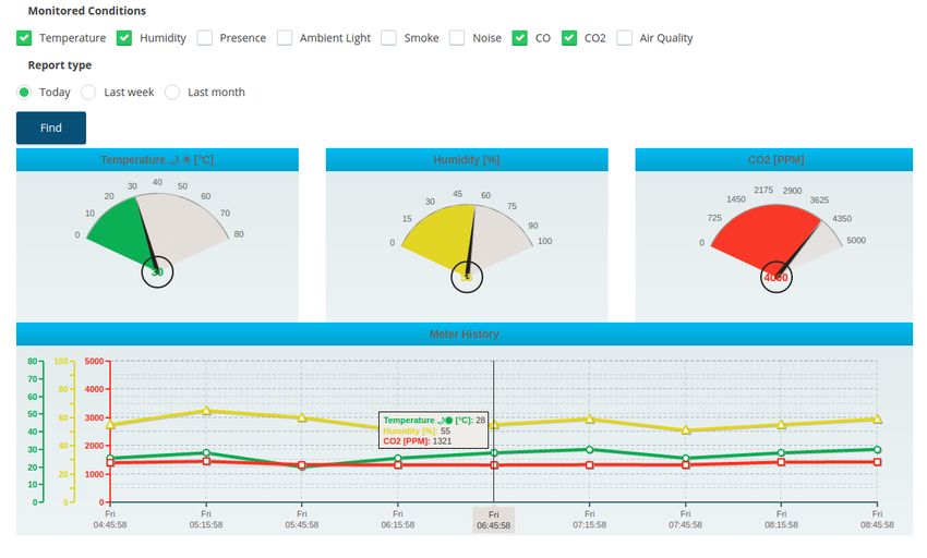
Electronics 2018, 7, 220                                                                            2 of 24

the favoured choice for most of them is to continue living autonomously in their own homes and
communities, with support from family, friends and caregivers.
     Depending on their functionality and design, AAL systems can be used for various purposes:
monitoring at home, intervention in case of emergency, or telehealth services. They all have the
same goal of allowing older adults to maintain an autonomous lifestyle in safety and with optimised
costs by discarding the need for constant caregiver supervision. To provide the required features,
the majority of systems comprise wireless sensor networks, medical devices and software applications
for monitoring and reporting. However, in many cases, these systems are cumbersome to deploy and
maintain, leave an unwanted visual footprint in the monitored person’s home and can be a source of
frustration or stress through the visible indicators of the person being constantly monitored.
     This paper describes the first prototype of i-Light, a pervasive cyber-physical system targeted
toward older adult supervision and home monitoring [4,5]. The system is being developed under
the umbrella of European Union research funding. One of its innovative aspects, as described in the
present paper, is that all system components are embedded in unobtrusive luminaires, providing the
following capabilities:

•     Continuous supervision of the monitored person’s indoor whereabouts and activities
      through localisation.
•     Constant monitoring of indoor ambient conditions in order to ensure the safety of
      monitored persons.
•     Real-time alerts and notifications provided to the monitored person and selected caregivers in
      case of emergency situations.
•     Interoperability with third-party medical devices for telehealth purposes.

     To achieve all these, the system is composed of a wireless network of sensors and a suite of
multi-platform software applications for indoor localisation, ambient data monitoring and analysis,
reporting and real-time alerting. In addition, an important innovation brought by i-Light is that the
nodes of the wireless network are custom developed energy-efficient luminaire devices embedded
with sensing, localisation and communication capabilities. As such, system deployment is simple
and inexpensive, requiring only the replacement of existing electrical illumination devices in the
household with the intelligent luminaires. This creates a pervasive and complete home monitoring
scheme, while removing current adoption barriers related to deployment complexity and associated
costs. Nevertheless, the system’s main advantage remains that it ensures timely assistance from family
members, friends and caregivers in case of emergency.
     The present work details the intelligent luminaires embedded with lighting and sensor modules,
the system’s software components, its communication capabilities and hardware-software integration.
Luminaires can be either smart or dummy, depending on their purpose. Both types are described
within the present paper. Software applications were conceived for indoor localisation, sensor data
collection, aggregation and analysis, as well as creation and visualisation of reports. Furthermore,
the system can create and send real-time alerts to monitored persons and designated caregivers in case
of emergency or undesired ambient conditions.

2. State of the Art
      Research required for the presented system spans several topics including ambient assisted living,
interior localisation and intelligent luminaires. We provide a concise account of the current state of the
art related to all three research directions, with particular emphasis on state of the art AAL systems.

2.1. Ambient Assisted Living
     Current technological solutions are targeted towards monitoring and offering support for several
vulnerable categories including people in nursing homes, people suffering from disease or disability,
or older adults living in their own homes.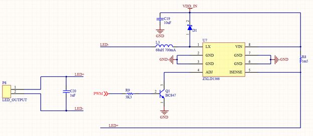
Electronics 2018, 7, 220                                                                             3 of 24

     Of these systems, we find the most relevant to be those designed for residential homes.
The electronic Medication Administration Record system (eMAR), a product of Extended Care Pro
company [6], provides alerts and reminders for taking prescribed medication, signalling medication
errors or missed follow-ups, performs various analyses and synchronises medication changes with
an associated pharmacy. Carevium Assisted Living Software [7] provides features for medication
administration, activity tracking, alerts and progress notes, appointments, physician communications,
pharmacy interactions and others. Yardi offers a senior living suite of solutions, among which the
Yardi EHR [8] and the Yardi eMAR [9] are of interest. The first one, an electronic health record system
enables senior living providers to enhance operations and care, to manage medication and streamline
caregivers’ tasks, while the second one helps improving resident care by ensuring safe medication
intake, enabling connections with pharmacies and consolidating medication management.
     Further, we focus on systems that target users living in their personal homes and who need
supervision due to specific conditions such as disease, disability or old age. The Necessity intelligent
system [10] includes an adaptive mechanism that considers the monitored person’s routines and
detects abnormal situations. Lynx [11] uses a wireless network of heterogeneous sensors to collect data
about the monitored person’s environment and daily activities. The data are used to infer activities
and identify behaviour patterns, which are subsequently employed by an expert knowledge system to
detect dangerous situations and send real-time alerts to caregivers. Considering these solutions, Lynx is
similar to the system we are proposing in regards to the provided features. However, its deployment
necessitates the installation of a multitude of heterogeneous sensors, while our system’s deployment is
easy, as existing light bulbs must only be replaced by the system’s intelligent luminaires. This also
reduces the supervised person’s mental discomfort, given that they will not feel constantly observed.
Another advantage of i-Light is given by its location detection algorithms that run uninterruptedly,
while in Lynx indoor positioning is achieved using presence sensors and sensors detecting door
opening. Finally, from a medical point of view, the two systems are quite different: while Lynx
extracts information from medical records to find correlations between the patient’s diagnosis, disease
and treatment, i-Light provides communication with third-party medical devices for monitoring the
person’s health status.
     Other systems which aim to determine a person’s activities for behavioural pattern identification
are described in [12–14]. These use either acoustic wireless sensor networks, comprised of audio and
ultrasound receivers, or video data. Acoustic features extracted from data allow the identification of
the monitored person’s current activity with a high degree of accuracy [12], automatic assessment of
the risk of falling (a serious threat to older adults’ well-being) [13] and the detection of gait related
parameters [14], which can be employed to determine user activity. From the point of view of
the final goal (person supervision and risk reduction), these systems are similar to the one we are
proposing. However, they achieve it by inferring current activities from several parameters measured
via acoustic or video devices, which should be installed within the residence, while our system uses
the embedded intelligent luminaires, which replace the existing light bulbs. Furthermore, i-Light is
more complex, as it monitors the environment for an increased level of safety and it communicates
with standards-compliant third-party medical devices to transmit data to a server, where it can be
accessed by caregivers and health professionals.
     In the area of home monitoring of neurological patients suffering from conditions such as epilepsy,
Parkinson’s and Alzheimer’s, the literature provides examples of solutions comprising sensors and
decision support systems for assisting both patients and doctors. Accelerometers attached to the
supervised person’s extremities and an unsupervised learning method contribute to seizure detection in
epileptic children [15,16]. Behavioural patterns of Alzheimer’s patients are identified via a probabilistic
approach [17], while hardware devices with pressure sensors and accelerometers that measure tremor
and a screening system including data analysis using feature selection and artificial neural networks
classification are used to provide decision support in case of Parkinson’s patients [18]. A proof of
concept for a digital assistant which provides clinical support to patients and facilitates medical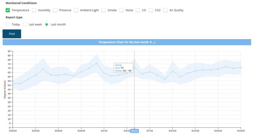
Electronics 2018, 7, 220                                                                             4 of 24

and caregiver intervention via smart voice recognition is presented in [19]. Considering patient
self-assessment provided using voice, the system provides feedback in the form of advice or warnings
and can trigger interventions in case of risk detection.
      There are also a few commercially available solutions. Healthsense [20] offers a service for
monitoring senior persons’ behaviour and activities via sensor networks and remotely alerts caregivers
about changes in routine, which could mean potentially dangerous situations. Although not present
in the current version, our system will also include an intelligent component, for which we have
already started research [21], to analyse activity patterns and to detect any deviations from them.
Additionally, the advantage of i-Light compared to Healthsense is represented by the intelligent
luminaires, which involve reduced deployment costs and by the supplementary feature of ambient
monitoring. Philips’ in-home monitoring devices [22] allow patients to take and transmit their own
vital signs and measurements to a server. Medtronic CareLink Network [23] uses specific devices
such as the Medtronic CareLink Home Monitor to allow sending data over a standard phone line or
the Internet to the clinic, connecting cardiac device patients with their clinician. The aforementioned
devices are focused on health monitoring, which is also one of i-Light features. This will be achieved
within the system via communication between the intelligent luminaires and medical standards
compliant devices that send data to the bulbs, which further forward them to the platform’s server.

2.2. Indoor Positioning
      The standard positioning service used for outdoor localisation is the well known Global
Positioning System (GPS), developed within the United States, and available globally. Competing
systems are the Russian GLONASS and the European Union developed Galileo system, expected to
become fully functional in 2019. A common limitation of these systems is that none work reliably when
indoors, due to interference caused by buildings and surrounding objects. While indoor positioning
systems have been developed, none of them are regarded as standard.
      The i-Light system uses well established wireless technologies to enable indoor localisation, and
therefore our focus in this section falls on similar efforts. However, we briskly mention other types of
indoor localisation techniques that have been proposed. One alternative to using wireless technology
is visible light communication using LED or OLED-based lighting [24], employed in systems such as
those offered by GE Lighting [25] or Acuity Brands [26]. In [27], the positions of laser points shot by
an unmanned aerial vehicle, in an indoor environment, are used to compute the vehicle’s location.
Acoustic background fingerprinting [28] or user movement [29] are other techniques proposed for
indoor positioning.
      The main difference between these systems and ours remains that wireless signal, unlike light,
is in most implementations omni-directional and it passes through walls and other obstacles. There are
two techniques exploited for this type of localisation: triangulation, i.e. angle calculation between
node and anchor points; and trilateration, i.e. distance measurement. Trilateration is usually preferred,
as it is less complex and less expensive. Most systems employ trilateration via the received strength
signal index (RSSI) [30], time of arrival (ToA) [31] or time difference of arrival, which can achieve
precision of up to a few centimetres [32]. Our choice for indoor localisation is trilateration, considering
its benefits mentioned above. Compared to the work in [32], our positioning algorithms obtain a higher
error (Section 6), but the aforementioned paper uses mobile nodes embedded in the person’s clothes.
As opposed to this method, our approach is less interfering, as the monitored persons do not need to
wear “smart” clothes and will not feel constantly observed given that our nodes are embedded within
the light bulbs. Therefore, we consider this error—guinea pig effect trade-off—advantageous for our
system. “Fingerprinting” is an approach that can be used with both Wi-Fi and Bluetooth technology
and which involves recording the RSSI in multiple locations within the indoor environment and later
the user’s location is computed using a prerecorded map [33]. The effectiveness of the newer Bluetooth
Low Energy (BLE) standard for indoor positioning has also been studied [34]. By exploring a variety
of algorithms and approaches, Dahlgren [34] concluded that BLE is suitable for indoor localisation,
Electronics 2018, 7, 220 5 of 24
offering reasonable accuracy and inexpensive deployment. Wi-Fi based fingerprinting and trilateration
have been experimented with for indoor localisation in [35]. Other methods based on trilateration,
using both Wi-Fi and BLE technologies with RSSI measurements are presented in [36–38], together
with means for noise and bias elimination, as well as for obtaining a good trade-off between accuracy,
deployment cost and effort.
Finally, we also mention a few commercially available solutions. Zonith’s real time location
system [39] is capable of locating persons, as long as they always wear a discoverable Bluetooth
device. Similar systems, based on Bluetooth or Wi-Fi beacons, or even ultra-wideband technology [40]
are provided by many companies, such as BlooLoc [41], Senion [42], Estimote [43], Pozyx [40] or
Infsoft [44].
2.3. Intelligent Luminaires
Light emitting diodes (LEDs) have revolutionised illumination technology, becoming the most
suitable candidates for new, intelligent illumination devices. Intelligent luminaires are relatively new
products and so far research and development have mostly been oriented towards somewhat basic
tasks, such as controlling light intensity. There are several bulbs on the market that allow remote
control of light intensity and colour. Using Wi-Fi technology, the Lifx bulb [45] can be controlled using
a smart phone, can change its colors and allows creating lighting schedules. The Lumen Smart Bulb [46]
is energy efficient, can create light in a spectrum of 16 million colours and can be controlled from
a mobile application using Bluetooth. Philips [47] and Elgato [48] offer similar products: as opposed to
other smart lights, Elgato Avea can also be controlled by Apple Watch via Bluetooth, while Philips Hue
provides lighting for security and the possibility of setting up timers and geofences. Additional sensing
is integrated in the iLumi smart bulb [49], which can detect presence and automatically light users’
path inside their homes.
Luminaires presented in [50] address the next level of complexity. Using incorporated
photosensors, they respond to daylight changes in the indoor environment, by dimming or increasing
light levels. Furthermore, these devices also have built-in occupancy sensors which allow them
to determine when a person is in the room and fade or switch off whenever necessary, leading to
significant energy savings.
The group of applications presented above is characterised by lighting control with smartphones
for security or energy-saving purposes, but not more. Our solution has a clear, innovative
advantage over the aforementioned existing solutions by: harnessing the current electrical and
lighting infrastructure to decrease the cost of the product and deployment; pervasive individual
monitoring to provide timely assistance to family members, friends, and informal and formal carers;
and interoperability with third-party devices. The intelligent luminaires composing the hardware
element of our platform include three main parts: an illumination module, a sensing module and a
processing unit (for more details, we refer the reader to Section 4). These components, together with
the software system of the i-Light platform, collaborate to achieve its final purpose: home monitoring,
assisted living and ensuring the safety of the monitored older adults.
3. Platform Overview
The high-level architecture of the cyber-physical system is illustrated in Figure 1. This section
presents the general overview of the platform, while details about its hardware and software
components are provided in Sections 4 and 5. The i-Light system [5] has two main components:
• Ambient tracking network: Sensors and hardware devices that perform ambient monitoring and
interior localisation of supervised persons.
• Multiplatform software applications: A software suite that includes Android and web applications
for ambient data monitoring, indoor localisation, analysis, reporting and real time alerting.Electronics 2018, 7, 220 6 of 24
Figure 1. High-level architecture of the system.
The system employs two types of luminaires dubbed dummy and smart. Together, they create
an area-wide coverage in which the signal strength from BLE emitting devices such as smartphones,
smart bracelets or Bluetooth beacons are recorded and used for positioning. As opposed to dummy
bulbs, which are simply used for light dimming and, indirectly, for indoor localisation purposes,
smart luminaires are also capable of environment sensing through an incorporated module, as well as
receiving data from medical devices. The luminaires are described in more detail in Section 4.
The system also includes all the required software components to leverage the available
hardware. The server web application is responsible for securely storing user profile data including
the deployment location’s layout, user preferences, notification settings and designated caregiver
permissions. The server also houses the data store, as well as data acquisition and client facing
subsystems which expose a web interface for customising preferences and managing smart bulbs.
Other substantial capabilities worth mentioning are the visualisation and reporting functionalities
available over the same web interface. Notifications and real time alerts can be received via short
message service or a smartphone application.
Our method of choice for indoor localisation is trilateration [36–38]. Our system uses at least
three nodes with known positions and the user’s coordinates are trilaterated using the received signal
strength indices. With regard to the technology employed, our experiments have shown that Bluetooth
appears more accurate for short distances, while Wi-Fi signal is better suited once the distance is
increased or when obstacles are added [37].
Smart nodes contain a sensor module, which includes sensors for monitoring various conditions.
For complex measurements, several physical measurements are aggregated. Abnormal values are
first validated with data acquired from the closest smart nodes, to rule out the possibility of errors.
There are three types of sensors in the module: environmental, presence and location. All readings are
sent to the server which stores them for creating alerts or for further analyses.
An essential component of the system is the real time alerting module. It continuously verifies
data received from sensors and checks them against a number of predefined system rules, as well as
user defined rules. In case readings are outside the permitted range, an additional reading is taken to
rule out the possibility of errors. If the reading is confirmed, an alert is generated by the system, and
transmitted according to preferences recorded within the system.Electronics 2018, 7, 220 7 of 24
4. Wireless Network of Intelligent Luminaires
This section details the most significant hardware components of the i-Light system. To ensure the
system is cost-effective, it consists of two kinds of luminaires: dummy bulbs and smart bulbs. Both device
types share the capability of dimming the LEDs, but they differ with regard to CPU power, available
communication interfaces and installed sensor array.
4.1. Dummy Bulbs
Dummy bulbs are built around a Bluegiga BLE112 Bluetooth Low Energy module [51] which is
used to establish connection with smart bulbs and accept commands from them. Dummy bulbs have
the capability of managing the intensity of their LEDs according to a value provided by the smart bulb
they are connected to. In addition, dummy bulbs perform Bluetooth scans in order to detect other
nearby devices and report their physical addresses and signal strength. Thus, these types of luminaires
are employed for indoor localisation, but only indirectly, by collecting RSSI values and sending them
to a smart bulb over Bluetooth.
4.2. Smart Bulbs
Smart bulbs are built around a single Raspberry Pi 3 board [52]. They share the capabilities for
LED intensity management with the dummy bulbs, as well as the capability of performing BLE scans
for detecting signal strength. In addition, they incorporate several sensing stages to sense temperature,
humidity, CO2 , dust and volatile organic compound (VOC) gases, as well as ambient light intensity.
Furthermore, smart bulbs incorporate a passive infrared sensor for detecting movement. Smart bulbs
can establish communication with the software server using both Wi-Fi and Ethernet connection. Signal
strength recorded by several bulbs is forwarded using a smart bulb to the software server, which runs
the localisation algorithm. Finally, an important functionality of smart bulbs is that, when connected
over BLE with a medical device implementing Bluetooth medical protocols or ISO/IEEE 11073 [53],
measured data are captured, aggregated and forwarded to the designated software endpoint over
a secure connection.
4.3. Lighting Module
Both smart and dummy bulbs contain an LED-based lighting module. LEDs were chosen due
to their efficacy, low energy consumption, reduction of electronic waste and suitability for being
controlled via software. Our project aims to advance the state of the art by augmenting these bulbs with
computing and communication resources to make them more useful, without significant additional
expense. To achieve this, the considered LED will employ a constant current driver that provides
longer operating life and less wasted heat than an alternative constant voltage driver.
The LED management stage is built around the Zetex ZXLD1366 [54] integrated circuit.
It is designed for driving single or multiple series connected LEDs with great efficiency from a voltage
source higher than the LED voltage. The device operates using an input between 6 V and 60 V.
This voltage range allows for the creation of several kinds of luminaires, in different sizes and number
of LEDs. Figure 2 shows the schematic of this LED dimming stage. The different elements of the
circuit are:
• P8 is a screw connection used to connect the LED set.
• VDD_IN is the power signal provided by the LED driver. The LED driver output can be up
to 60 V and it is obtained from the mains. This signal is introduced to the PCB board using
a screw connection.
• R8 is a resistor that sets the nominal current provided to the LEDs.
• PWM is the signal provided by the BLE module that sets the desired dimming applied to the
LED set.
• C19, L3 and D1 are electronic components required for proper operation of the ZXLD1366 circuit.Electronics 2018, 7, 220 8 of 24
Figure 2. Schematic of the LED dimming stage.
To achieve the LED dimming stage in both dummy and smart bulbs, the components are placed
both at the top and at the bottom of the printed circuit board to meet placement constraints required
for the proper operation of the ZXLD1366 and to reduce the board size, thus facilitating the printed
circuit board’s integration into different luminaire designs.
4.4. Sensor Module
Smart nodes are endowed with a sensor module containing sensors that can be classified in three
main categories: environmental, presence and location. The module senses ambient light, temperature,
humidity, dust, volatile organic compounds and carbon dioxide gas. Furthermore, it also senses the
presence of people as well as nearby BLE devices. Sensor data formats and interfaces are different.
There are sensors that offer an analog output that must be digitally converted, while others allow
connection and internal register readings using serial communication protocols. In terms of power
supply, most sensors accept a specific range of voltages, so two power supply levels are required:
3.3 V and 5 V. Table 1 illustrates all implemented sensor types together with their characteristics.
Table 1. Sensors and their characteristics.
Output Required Power Applied Power
Sensor Magnitude
Type Supply (V) Supply (V)
Humidity and
SHT21 [55] Digital I2C 2.1 to 3.6 3.3
temperature
AMS302 [56] Ambient light Analog 3.3 3.3
Winsen WSP2110 [57] Air quality Analog 5 5
Winsen MG812 [58] CO2 Analog 5 5
GP2Y1010AU0F [59] Smoke/Dust Analog 4.5 to 5 5
EKMC1601111 [60] Presence Digital GPIO 3.3 3.3
Presence and 3.3 or 5, depending on
GridEye [61] Digital I2C Both correct
location the mounted version
4.5. Communication Interface
As illustrated in Figure 1, data flow in the direction of smart nodes, and from smart nodes to
the software server. Inter-node communication is achieved via Bluetooth, while smart node to server
communication is achieved using Wi-Fi or Ethernet, depending on deployment location.Electronics 2018, 7, 220 9 of 24
4.5.1. Communication between Smart and Dummy Luminaires
Bluetooth Low Energy (BLE) is the chosen technology for inter-bulb communication. Its suitability
is proven by its reduced power and cost requirements, as well as proper range and transmission speed.
The dependable range for BLE is up to 50 m line of sight, but this requires increased transmission
power and affects battery life. An effective range for BLE that provides good balance with battery life
is between 2 and 5 m. This also depends on device and antenna design, as well as the presence of
obstacles between and around communicating devices [62].
To establish a BLE connection, one device must act as a master and the other device as a slave.
Typically, the dummy bulb advertises itself and the smart bulb performs a scan to detect dummy bulbs
nearby. Once detected, the pairing process occurs and the connection is established, so the smart bulb
acts as master and the dummy bulb as slave. The master device cannot emit advertising packets as it
has no sense in this role. This limitation is a problem as one of the dummy bulb’s tasks is to scan the
environment and maintain information regarding other nearby devices. To achieve this, dummy bulbs
need to act as master but, in parallel, they need to accept connections from smart bulbs. The adopted
solution has been to change the dummy bulb role in time, defining a period to act as master and
a period to act as slave. During its master period it scans the environment searching for nearby devices,
after which it advertises itself in order to establish a connection with a smart bulb and act as data
producer. This mechanism adds complexity to the dummy bulb firmware as there is a software timer
and a counter that controls when the scans take place, when they are stopped, and when device role
must change. Moreover, when changing device role, several actions must be performed to make the
gathered information available.
The Bluetooth SIG defines the Attributes Protocol [63] for BLE devices, a client/server protocol
where attributes are configured and grouped into services using the Generic Attribute Profile
(GATT) [63]. The profile describes a use case, roles and general behaviours based on the GATT
functionality. Services are collections of characteristics and relationships to other services that
encapsulate the behaviour of part of a device. Profiles and services that describe node capabilities are
developed and customised as part of the project to enable power-efficient data transfer. The GATT
database is defined using an XML file. The GATT structure implements one or more profiles,
each profile consists of one or more services and each service has of one or more characteristics.
Some examples of services that have been defined are: the LED dimming control, which has only one
characteristic that corresponds to the PWM value; the BLE devices detected nearby (see Figure 3)—
this service has ten characteristics, one for each device in the list, all characteristics are readable and
each one occupies 6 bytes; the RSSI level of the BLE devices, which has ten characteristics, one for each
device in the list; and a service that offers a counter for each detected BLE device in the list.Electronics 2018, 7, 220 10 of 24
Figure 3. Sample from ten position service list storing detected BLE devices.
Dummy nodes will be installed within range of a smart node to ensure accurate tracking as well
as suitable battery life. Additional consideration will be given to trilateration to ensure that the signal
coverage is adequate for obtaining the desired precision. This is facilitated by the fact that dummy
nodes are powered using long-life batteries, which allows their deployment to be less constrained
by location.
4.5.2. Communication between Smart Bulbs and the Server
The sensor network communicates with the software server over Wi-Fi. In opposition to
BLE, Wi-Fi is long-range and has much higher data rate. Conversely, it also presents high power
consumption [64,65]. Wi-Fi equipped smart luminaires are socketed and replace the lighting system
within the deployment location. Considering its relatively high transmission power, and operation in
the 2.4 Ghz band, Wi-Fi networks can cause interference with other wireless technologies, including
BLE. Our project addresses this issue by ensuring that enough physical separation exists between
nodes, while on-site testing the deployment. Most luminaires are ceiling-mounted, therefore we expect
low interference for smart node Wi-Fi. In addition, given that smart nodes are also BLE enabled,
interferences within a node are addressed using software. As dummy nodes are small size and battery
operated, they can be located out of the Wi-Fi interference range.
Communication between smart nodes and the software server is neither bandwidth nor
power limited, thus data are transferred using the JavaScript Object Notation (JSON) format [66].
Each message includes the sender’s unique identifier, timestamp, the reading value and unit of
measurement. An example JSON for temperature reading is shown in Figure 4. Similar messages are
used for humidity, smoke, dust, air quality, CO2 level, ambient light and presence.
Figure 4. Smart bulb reading in JSON format
Given the sensitive nature of transmitted data, security and privacy are paramount. This is
especially important in light of the EU-level adoption of the General Data Protection Regulation [67],
which represents a large reformation with regard to data protection and which aims to address privacy
issues in the digital domain. While Wi-Fi provides data encryption, existing research demonstratesElectronics 2018, 7, 220 11 of 24
its insufficiency [68]. Our system addresses this by including an additional layer of application-level
encryption over all transmitted data. Data sent between dummy and smart bulbs, as well as from
the smart bulbs to the server, are encrypted using the Advanced Encryption Standard (AES) [69].
This prevents access of outside actors to transmitted data, and also prevents man-in-the-middle attacks.
Furthermore, application level encryption provides greater flexibility for system deployment, as data
remain safe even when transmitted over unencrypted networks.
4.6. Processing Unit
The processing unit within the smart bulbs was designed considering the following factors:
• Easy integration into an LED-based luminaire.
• Correct positioning of the sensor module in order to avoid interference generated by other
luminaires, as well as to provide accurate readings.
• Metallic components of the luminaire must not provide interference with the processing unit’s
wireless communication chip.
The processing unit’s current prototype is built around a Raspberry Pi 3 Model B [52] main
board. Compared to other board types, the Raspberry Pi proved to be more powerful, complex,
reliable and suitable to our requirements. Furthermore, it includes communication interfaces for Wi-Fi
and Bluetooth.
Taking into account previously mentioned factors, the processing unit uses a modular design
and consists of two main components. It incorporates three boards that can be connected using board
to board connectors or just wires so that they can be adapted to almost any LED luminaire design.
The first component is the Raspberry Pi board and the power management stage; the second integrates
two printed circuit boards that comprise all available sensor types. Ensuring proper communication
between smart and dummy bulbs, as well as between bulbs and other devices was one of the major
reasons that drove us towards a two-component design. As such, the Raspberry Pi and antenna,
which must be free of metallic parts that could cause signal shielding effects, are mounted upside
down. This is done given that most luminaires are affixed to the ceiling and that devices they
communicate with are located physically underneath them.
This modular approach provides the required flexibility for placing composing elements within
the luminary design. In the case of a round luminaire, for instance, the sensor module could be placed
in the centre and the main board at the periphery. Moreover, the modular design avoids situations in
which the heat emitted by the Raspberry Pi unit would cause the temperature and humidity sensors to
read distorted values.
The final prototype, illustrated in Figure 5 incorporates the required stage to get the appropriate
power supply from the mains, as well as an AC/DC transformer that provides 5 V DC output. In this
board, the Raspberry Pi is mounted upside down to facilitate the assembly process and to put the
antenna upside down for maximum signal strength. The sensor module is comprised of two boards,
one of which is mounted vertically and the other horizontally. The components of the device are
connected to the Raspberry Pi using its expansion header. The pins in this connector can be grouped
as follows:
• Power and earth pins: The Raspberry Pi board outputs two different voltage levels: 3.3 V and
5 V. The first one is generated by an internal step-down regulator from the original 5 V level.
Normally, the board is fed connecting an external power supply to the micro USB connector.
However, this is not a suitable option in our case. Thus, we provide an external 5 V voltage
level using this connector. Unfortunately, if done in this way, a protection stage is bypassed.
Thus, this protection stage has been replicated and placed in the main board. Finally, there are
several ground connections, all of them are routed to the main board earth.
• General purpose digital inputs and outputs: These can be used as common digital inputs or
outputs or as a method to enable or disable certain stages.Electronics 2018, 7, 220 12 of 24
• Universal Asynchronous Receiver/Transmitter: There are two pins dedicated to this. By default,
this interface is used to provide a Unix shell. In this case, this feature is disabled and we use this
interface to gather debugging data.
• I2C PORT: This port is used to communicate with the humidity, temperature and GridEye sensors.
• SPI PORT: The port is used to communicate with the analog to digital converter (for the
sensor module).
Figure 6 shows how the different components of the design are connected. All components
are connected to the Raspberry Pi using its expansion header. The processing unit executes a
software application which currently provides the following features, with existing possibility for
further extension:
• Sensor module management. Each sensor has its own software library and the information must
be accessed in different ways, using either digital interfaces or analog outputs.
• Dummy bulb management, and reception of the devices detected by the bulb.
• Room illumination management, according to the user’s configuration, for the bulb itself together
with all connected dummy bulbs.
• Management of communication with devices following the IEEE 11073 standard.
Figure 5. Printed circuit board and processing unit.
Figure 6. Connections between the different components of the design.
5. Software Architecture
The general architecture of the system is shown in Figure 7. The system has a distributed
architecture, with information gathered and processed across different system levels and components.Electronics 2018, 7, 220 13 of 24
The components are deployed on different devices: smart and dummy luminaires, the software
server and client devices such as smartphones or other wearables. In the present section, we detail
each component.
Figure 7. Software architecture of the system [5] (IEEE 978-1-5386-3368-7/17/$31.00 c 2017).
5.1. Administration
The administration component is essential for all other elements of the software system, which are
described subsequently in this section. Management of system users and their residences, as well
as managing and configuring the intelligent luminaires are all centrally handled by this component.
Entering a new residence involves entering user data and building a two-dimensional representation
of their home. The system provides functionality for drawing walls, adding furniture, labeling rooms
and generating a three-dimensional plan of the dwelling. A particular step in the process is adding
the smart and dummy bulbs to the location plan. Luminaires can be placed and configured directly
from within the application; both bulb types require providing a MAC address, and for smart bulbs
available sensors must be selected from a list. Smart bulbs must also be configured in order to enable
connecting them to the user’s home wireless network.
5.2. Geolocation
The Geolocation Component is responsible for indoor localisation of tracked persons or objects
that have a Bluetooth emitter attached. A series of experiments have been performed to identify the
best solution for indoor localisation [4,36,37,70,71]. Each of the luminaires captures Bluetooth signal
strength from emitting devices together with their MAC address and timestamp. Dummy luminaires
forward these data to the smart ones which aggregate signal strength readings and forward the
information to the software server. The software server aggregates received data with the location
layout and performs the trilateration to obtain the current position of the target, which is persisted
in the system’s data store. For the trilateration algorithm, we have used a non-linear least squares
optimisation, the Levenberg–Marquardt Optimiser, which finds a local minimum by interpolating
between the Gauss–Newton algorithm and the method of gradient descent [72]. Running trilateration
on the server-side allows fine-tuning the algorithm by setting individual correction constants per
location in order to improve its accuracy.
5.3. Reporting
The Reporting subsystem is responsible with creating relevant and customisable reports based
on administrative, sensor and alert data. The reports can be textual or visual, conveying optimal
visualisation for better insight. Various filters can be applied to aggregate corresponding data forElectronics 2018, 7, 220 14 of 24
queries such as start and end dates, indoor location or ambient condition type. The system currently
provides the following report types:
• User report. It includes administrative data such as user name, email, telephone number, age, and
deployed device identifiers; this report can only be requested by the system administrator.
• Interior localisation report. The report displays indoor localisation information relevant for
caregivers. It includes location, start and end times and total period spent in each particular
location. This is available for caregivers and administrators.
• Environmental data report. It can be requested by all user types and shows data regarding ambient
conditions such as temperature, humidity, smoke and gases.
• Alerts report. This report is available to administrators and caregivers and presents a summary
about generated alerts and notifications, including alert type, source, destinations and alert time.
The reporting component is deployed on the software server and can be accessed by the client
device application. Accessing the reports requires authentication and authorisation according to
preset permissions.
5.4. Data Analysis
The data analysis component is responsible for collecting, processing, aggregating and analysing
received sensor readings to generate alerts, notifications or infer behaviours. Any abnormal readings
are first validated with data from other close-by smart nodes to check for sensor malfunction before
issuing a real time alert. For example, in the case of an abnormal high temperature, an increased
temperature should also be read from close-by sensors. Currently, the hardware provides the following
data for analysis [5]:
1. Environmental measurements:
• Temperature, measured in degrees Celsius.
• Relative humidity, measured as a percentage.
• Ambient light, measured as a percentage.
• Smoke presence, measured as a boolean value.
• Air quality, measured in parts per million by volume; this includes the concentration of
carbon dioxide and volatile organic compounds.
2. Presence is detected using the GridEye sensor, which produces a matrix of values. The raw
sensor data must be processed to detect human presence based on the difference in detected
infrared signature.
3. Location is computed starting from RSSI combined with device MAC addresses.
Abnormal readings are identified using a predefined set of default rules, available for each
measurement. System users can redefine these rules, or provide additional ones to customise the
system. When data analysis reveals that sensor readings do not comply with at least one of the defined
rules, an action is taken in real time. This can either be passive, i.e. setting a software flag that will be
seen by the system administrator or a designated caregiver in the application, or active, in which case
a real-time alert is generated and forwarded to the monitored person and their caregivers. While the
default set of rules covers typical values for a residential building, additional rules can be created for
each deployment location.
5.5. Real-Time Alerts
This component is responsible for sending real-time alerts to monitored persons as well as their
registered caregivers. In the current implementation, alerts are created when sensor readings are
outside the permitted range for at least one of the defined rules. Each alert is stored on the server as aElectronics 2018, 7, 220 15 of 24
record containing the device responsible for the reading, the measurement type and value, its severity
and the timestamp of the reading.
To send alerts, a database listener is triggered every time an alert is stored. As mentioned in
the previous section, the actions taken for an alert are specified within the rule(s) that were used
to generate it. Alerts can either result in a software notification that can be consulted through the
application’s web interface, or they are sent in the form of a text message to the monitored person
as well as their designated caregivers. In addition, as part of the project, a prototype smartphone
application that employs push notifications to receive alerts was implemented and is expected to be
available in an upcoming system version.
6. System Validation
The current implementation of the cyber-physical system was deployed to a real environment.
Intelligent luminaires were placed for evaluation in three rooms: one bedroom, a study room and
a hallway.
The main objective of the deployment was to evaluate whether the most significant technical
challenges were fully addressed within the technical work. These included ensuring that intelligent
luminaire design and assembly does not interfere with data readings, that sensor readings are
consistent and correct, interior localisation is accurate and that the hardware-software connection is
reliable. This was achieved using a combination of real-life and simulated data transmitted over the
Wi-Fi network.
6.1. System Integration
The experimental evaluation was undertaken within three rooms of a dwelling, namely a
2.50 m × 3.30 m bedroom, a 2.50 m × 1 m study room and a 2.40 m × 2.22 m hallway. The dwelling also
includes a kitchen and bathroom, but these have not been considered in our evaluation. Both indoor
and outdoor walls are brick and reinforced concrete. This is particularly significant for the positioning
algorithm, as these materials strongly influence RSSI values.
The first step in installing the system is to set up a smart bulb to which dummy bulbs are
associated. When first deployed, the smart bulb creates a wireless network through which the system
exposes a web application where the user can set up the location and house plan. The location of all
deployed bulbs must be entered for accurate indoor localisation, as illustrated in Figure 8. In addition,
the web application allows providing the capabilities of smart and dummy bulbs as well as registering
the monitored person and their designated caregivers. The final step is to configure the Wi-Fi network
through which the system will connect to the cloud-based software server.
Figure 8. Bulb placement.Electronics 2018, 7, 220 16 of 24
After initial configuration the user can customise the system, ask for reports or obtain real-time
status for the monitored buildings they have access rights to. Figure 9 illustrates the monitoring
dashboard that provides information about current ambient conditions and past values.
Figure 9. Example of daily ambient report for temperature, humidity and carbon dioxide.
The system also provides an option to show the evolution of ambient conditions over past weeks
or months, as shown in Figure 10, using charts and tables. Reports are also available for existent users,
person location and activities, as well as alerts.
Figure 10. Monthly ambient report—temperature.Electronics 2018, 7, 220 17 of 24
6.2. Positioning
Achieving accurate indoor positioning represents one of the most innovative parts of the
system, with significant associated technical risk. As such, to reach a suitable implementation,
experimentation with positioning algorithms and methods was performed using dedicated prototypes
and testing scenarios from the first phases of the project. Experimentation results are detailed in
[36–38]. The experiments used various settings, covering many real-world scenarios, including setting
anchor points on different floors or in the corner of the rooms [37], performing the tests in locations
with heavy wireless interferences [36] or choosing an asymmetric placement of anchor points [38].
These experiments used rudimentary versions of the system’s nodes, as they were targeted particularly
towards indoor localisation, given that the goal was to improve the positioning algorithms to be used
in the system prototype. Results showed that detection with room-level accuracy can be achieved
using either Bluetooth or Wi-Fi, without prior location fingerprinting. In addition, we observed that
the presence, configuration and materials walls are built from have a larger effect on localisation results
than that of enclosure size. Therefore, we undertook our evaluation in a smaller physical location,
but one having reinforced concrete and brick walls. Basic trilateration with one bulb per room was
considered suitable for the project’s requirements. Improved accuracy is possible using a more refined
algorithm that employs corrections, as presented in [38].
This article describes indoor localisation testing as a subsystem of the i-Light system, having tested
the localisation independently as mentioned in the previous paragraph . We employed a complete
workflow that includes installation, room and bulb setup, positioning feedback and reporting. A smart
luminaire was set-up in each room and different positioning scenarios were tested. In the first three
scenarios, the tracked person is in the middle of each room, close to the respective luminaire. In the
fourth and fifth scenarios, the tracked person is in equal range of the three luminaires; in the fourth,
the doors are opened, while, in the fifth, the doors are closed. The application’s real time output is
illustrated in Figures 11 and 12. For this test, we used direct trilateration. To obtain the distance from
the strength of the signal, we used the RSSI lognormal model described in [73], in which the distance
can be inferred as:
d = 10( A− RSSI ) /(10 ∗ n) (1)
where n represents the path-loss exponent and ranges between 2 to 6 for indoor environments. We used
n = 2 for our experiments. A is the received signal strength expressed in dBm measured at one meter,
and is known for each luminaire. Signal strength was recorded every 6 s over a 5 min interval,
during three different intervals of time and then averaged. Outliers were discarded. The figures show
luminaire placement, as well as both the correct and inferred positions of the monitored person.
Scenario 1 is illustrated in Figure 11 (left). The monitored person is sitting on the bed, and is
detected with an average error of 64 cm.
In Scenario 2, illustrated using Figure 11 (middle), the average localisation error is of 85 cm, and
provides correct room-level detection. Scenario 3 is illustrated in Figure 11 (right), with the person
standing in the hallway, localised with an average error of 131 cm.
Scenarios 4 and 5 are shown in Figure 12. The person is at equal distance from all luminaires.
In Scenario 4 (Figure 12, left), interior doors are open and the person is localised with an average error
of 66 cm. Scenario 5 repeats Scenario 4, but with closed doors. Accuracy slightly decreases and the
person is localised with an average error of 84 cm.
Table 2 summarises the obtained experimental results. As the results have shown, achieved
positioning is correct for room-level localisation in most probable settings, without any a priori set up
or signal fingerprinting.Electronics 2018, 7, 220 18 of 24
Figure 11. Localisation tests. Luminaires are represented using yellow circles with black border,
the person’s real position is represented using the green cross shape and the detected position is shown
using the red diamond.
Figure 12. Open and closed-door localisation tests. Person at equal distance from all luminaires.
Luminaires are represented using yellow circles with black border, the person’s real position is
represented using the green cross shape and the detected position is shown using the red diamond.
Table 2. Positioning details, for all analysed scenarios.
Real Location Computed Location Error
Scenario 1 (547, 44) (506, −6) 64 cm
Scenario 2 (583, 208) (506, 171) 85 cm
Scenario 3 (314, 182) (410, 96) 131 cm
Scenario 4 (523, 125) (457, 124) 66 cm
Scenario 5 (523, 125) (440, 138) 84 cm
6.3. Alerting
Ambient condition information is periodically sampled by the smart bulbs and transmitted to
the software server. At a predefined time interval (currently 15 s), all recorded values, for all types
of environment conditions, are analysed and compared against the correct values defined by the
default or custom business rules. Should any inadequacy be identified, an alert is immediately created
and stored in the database. Each such alert contains information about: the timestamp when it was
generated, the type, value and unit of measurement for the involved ambient condition, the MAC
address of the smart node that recorded the abnormal value, and the room where this node is located.
In addition to anomalous environment conditions, person presence in certain locations and for certain
periods of time may also indicate a risky situation. For instance, if the monitored person spends more
hours in the bathroom or in the bedroom, but not on the bed or on a chair, he/she might be in need of
help. Such situations are also regulated by the system and new custom rules can be added to handle
them. Person location is computed by the system in real time and, furthermore, verification is made atElectronics 2018, 7, 220 19 of 24
a predefined time interval (currently 15 s) to detect whether the position has unchanged. Alerts are
then generated according to the rules and the modification in person position, in a similar manner to
the environment conditions.
Alerts generated by the corresponding component are sent using short text message service by
integrating a K4505 GSM broadband modem and the Gammu SMS Daemon [74] with the application
server. Figure 13 illustrates two examples of alerts sent by the system. The first involves the temperature
parameter, which exceeded the maximum allowed value. This was generated using simulated data,
as during system testing there were no interior environment anomalies. The second alert involves
the monitored person’s prolonged presence in the bathroom. This was generated as a consequence
of an existing business rule which states that presence within such a room should not be longer than
one hour.
Along with sending the alerts via SMS, the system also shows these notifications within the
application’s web interface, where they can be consulted at will. However, sending a real-time message
to the user’s and the caregiver’s telephones is not only more effective, but even indispensable in the
case of dangerous scenarios. In addition to these two types of communication, a prototype smartphone
application to receive alerts is also being developed.
Figure 13. Received SMS alerts regarding the temperature parameter and prolonged presence in a room
where presence time should be shorter (bathroom).
7. Conclusions
The current trend in population ageing, as well as increasing costs of geriatric healthcare require
adaptive, intelligent, innovative technology to lessen the burden on both seniors and their primary
caregivers. This paper presents the design and implementation of the i-Light system for ambient
condition and indoor monitoring of older adults in their own residences. The system incorporates
a wireless network of custom developed intelligent luminaires, a software server and a suite of
mutiplatform software applications and its proper functioning relies on an impeccable cooperation
between all these components.
i-Light is the product of collaboration between industry and academia under the framework
of the Eureka Eurostars research funding program. The current system implementation provides
ambient condition monitoring, room-accurate indoor localisation, configuration capabilities for alert
generation and severity using customisable business rules together with generation and transmission
of real-time alerts.
Compared to other ambient assisted living systems, i-Light’s innovation includes the design and
implementation of novel, energy efficient luminaires, with embedded sensing, indoor localisation
and communications electronic system that enable a pervasive, seamless, and inexpensive home
monitoring scheme. Using these intelligent luminaires as network nodes allows harnessing theYou can also read