Australia Pacific LNG Project - Commissioning and Start-Up Environmental Management Plan 18-Dec-2014
←
→
Page content transcription
If your browser does not render page correctly, please read the page content below
Australia Pacific LNG Project
Commissioning and Start-Up Environmental
Management Plan
18-Dec-2014

301001-00752 - 00-EN-REP-0335 - APLN-000-EN-R01-D-25659
AUSTRALIA PACIFIC LNG PTY LIMITED
AUSTRALIA PACIFIC LNG PROJECT
COMMISSIONING AND START-UP ENVIRONMENTAL MANAGEMENT PLAN

Contents
1.         Introduction ........................................................................................................................ 1

     1.1   Background ........................................................................................................................ 1

     1.2   Scope of the Commissioning and Start-Up Environmental Management Plan ................. 1

     1.3   Structure and content ......................................................................................................... 7

     1.4   Related documents ............................................................................................................ 8

2.         Overview of LNG facility and CSU activities .................................................................... 10

     2.1   LNG facility description .................................................................................................... 10

           2.1.1       Receiving and metering ...................................................................................... 13

           2.1.2       Pre-treatment ...................................................................................................... 13

           2.1.3       Liquefaction ......................................................................................................... 14

           2.1.4       Flare and vent system ......................................................................................... 15

           2.1.5       LNG storage and loading .................................................................................... 15

     2.2   Associated infrastructure.................................................................................................. 16

           2.2.1       Power generation ................................................................................................ 16

           2.2.2       Water supply ....................................................................................................... 16

           2.2.3       Stormwater .......................................................................................................... 16

           2.2.4       Potentially contaminated stormwater .................................................................. 19

           2.2.5       Wastewater ......................................................................................................... 19

     2.3   General Commissioning activities .................................................................................... 20

     2.4   LNG facility component-specific Commissioning activities .............................................. 21

           2.4.1       AGRU cleaning system ....................................................................................... 21

           2.4.2       GT compressors .................................................................................................. 21

           2.4.3       AHOHs ................................................................................................................ 21

           2.4.4       Flare and vent systems ....................................................................................... 21

           2.4.5       GTGs ................................................................................................................... 21

           2.4.6       General Start-Up activities .................................................................................. 21

     2.5   LNG facility component-specific Start-Up activities ......................................................... 22

           2.5.1       AGRU incinerator and NRU-thermal oxidiser ..................................................... 22

           2.5.2       GT compressors .................................................................................................. 23

           2.5.3       AHOHs ................................................................................................................ 23

301001-00752 - 00-EN-REP-0335 - APLN-000-EN-R01-D-25659
Rev 2 - 18-Dec-2014
                                                                      Page iii
AUSTRALIA PACIFIC LNG PTY LIMITED
AUSTRALIA PACIFIC LNG PROJECT
COMMISSIONING AND START-UP ENVIRONMENTAL MANAGEMENT PLAN

           2.5.4       Flare systems ...................................................................................................... 23

           2.5.5       GTGs ................................................................................................................... 23

3.         CSU environmental values .............................................................................................. 24

     3.1   Assessment of potential CSU impacts on environmental values .................................... 25

4.         Potential impacts from CSU activities .............................................................................. 27

     4.1   Air quality ......................................................................................................................... 27

           4.1.1       CSU activities and potential impacts ................................................................... 27

           4.1.2       Objectives and targets......................................................................................... 28

           4.1.3       Control strategies ................................................................................................ 30

           4.1.4       Monitoring and reporting ..................................................................................... 35

     4.2   Noise and vibration .......................................................................................................... 35

           4.2.1       CSU activities and potential impacts ................................................................... 35

           4.2.2       Objectives and targets......................................................................................... 35

           4.2.3       Control strategies ................................................................................................ 36

           4.2.4       Monitoring and reporting ..................................................................................... 37

     4.3   Water ................................................................................................................................ 39

           4.3.1       CSU Activities and potential impacts .................................................................. 39

           4.3.2       Objectives and targets......................................................................................... 39

           4.3.3       Control strategies ................................................................................................ 40

           4.3.4       Monitoring and reporting ..................................................................................... 43

     4.4   Dangerous Goods and other chemicals........................................................................... 43

           4.4.1       CSU activities and potential impacts ................................................................... 43

           4.4.2       Objectives and targets......................................................................................... 44

           4.4.3       Control strategies ................................................................................................ 45

           4.4.4       Monitoring and reporting ..................................................................................... 48

     4.5   Waste ............................................................................................................................... 48

           4.5.1       CSU activities and potential impacts ................................................................... 48

           4.5.2       Objectives and targets......................................................................................... 48

           4.5.3       Overarching waste management approach ........................................................ 49

           4.5.4       Control strategies ................................................................................................ 50

           4.5.5       Monitoring and reporting ..................................................................................... 52

           4.5.6       Waste management practices review ................................................................. 52
301001-00752 - 00-EN-REP-0335 - APLN-000-EN-R01-D-25659
Rev 2 - 18-Dec-2014
                                                                      Page iv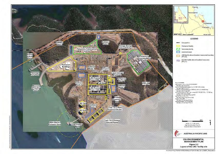
AUSTRALIA PACIFIC LNG PTY LIMITED
AUSTRALIA PACIFIC LNG PROJECT
COMMISSIONING AND START-UP ENVIRONMENTAL MANAGEMENT PLAN
5. CSU general environmental management ....................................................................... 53
5.1 Roles and responsibilities ................................................................................................ 53
5.2 Competency and training ................................................................................................. 54
5.2.1 Additional environmental training ........................................................................ 55
5.2.2 Toolbox talks and Daily Information Sheets ........................................................ 55
5.2.3 Work Method Statements .................................................................................... 55
5.3 Monitoring, auditing and reporting ................................................................................... 56
5.4 Corrective actions, reviews and continuous improvement............................................... 56
5.5 Document control and record keeping ............................................................................. 57
5.6 Health, Safety and Environment ...................................................................................... 57
5.6.1 Environmental incidents ...................................................................................... 57
5.6.2 Emergency preparedness and response ............................................................ 57
List of Figures
-1 LNG facility location ............................................................................................................... 3
Figure 1
Figure 1-2 Matters of National Environmental Significance in relation to the stormwater outfalls and air
emission release points ........................................................................................................................... 4
-3 Interaction between Construction, CSU and Operations EMPs ............................................ 5
Figure 1
Figure 2-1 Schematic of the Optimized Cascade® process ................................................................. 10
Figure 2-2 Layout of the LNG facility ..................................................................................................... 12
Figure 2-3 Stormwater management system overview ......................................................................... 18
Figure 4-1 Air Emission Points .............................................................................................................. 29
Figure 4-2 Waste management hierarchy ............................................................................................. 49
List of Tables
Table 1-1 Definition of phases including Construction, CSU and Operations ......................................... 6
Table 2-1 Stormwater release points .................................................................................................... 17
Table 4-1 CSU activities and potential impacts to air quality ................................................................ 27
Table 4-2 Objectives and targets for management of potential impacts to air quality .......................... 28
Table 4-3 Air quality environmental control strategies .......................................................................... 30
Table 4-4 CSU activities and potential impacts to noise environment .................................................. 35
Table 4-5 Objectives and targets for management of potential impacts to the environment from noise
and/or vibration ...................................................................................................................................... 35
301001-00752 - 00-EN-REP-0335 - APLN-000-EN-R01-D-25659
Rev 2 - 18-Dec-2014
Page v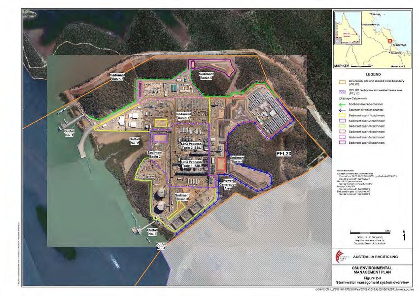
AUSTRALIA PACIFIC LNG PTY LIMITED
AUSTRALIA PACIFIC LNG PROJECT
COMMISSIONING AND START-UP ENVIRONMENTAL MANAGEMENT PLAN

Table 4-6 Commissioning activities and control strategies to manage impact to the noise environment
............................................................................................................................................................... 36

Table 4-7 Noise limits for the LNG facility at sensitive receptors .......................................................... 37

Table 4-8 CSU activities and potential impacts to water ....................................................................... 39

Table 4-9 Objectives and targets for management of potential impacts to water ................................. 39

Table 4-10 CSU activities and control strategies to manage impact to water ....................................... 40

Table 4-11 Stormwater discharge quality objectives ............................................................................. 43

Table 4-12 CSU activities and potential impacts relevant to dangerous goods and other chemicals .. 43

Table 4-13 Objectives and targets for management of potential impacts associated with dangerous
goods and other chemicals.................................................................................................................... 44

Table 4-14 Commissioning activities and control strategies relevant to dangerous goods and other
chemicals ............................................................................................................................................... 45

Table 4-15 CSU activities and potential impacts relevant to waste ...................................................... 48

Table 4-16 Objectives and targets for management of potential impacts associated with waste......... 49

Table 4-17 Method of management of each waste type generated during Commissioning ................. 50

Table 5-1 Construction and CSU environmental roles and responsibilities .......................................... 53

301001-00752 - 00-EN-REP-0335 - APLN-000-EN-R01-D-25659
Rev 2 - 18-Dec-2014
                                                                            Page vi
AUSTRALIA PACIFIC LNG PTY LIMITED
AUSTRALIA PACIFIC LNG PROJECT
COMMISSIONING AND START-UP ENVIRONMENTAL MANAGEMENT PLAN
1. Introduction
1.1 Background
The Australia Pacific LNG Project is a coal seam gas (CSG) to liquefied natural gas (LNG) operation
in Queensland developed and operated through a joint venture partnership between Origin Energy
Limited (Origin; 37.5% interest), ConocoPhillips Australia Pty Ltd (ConocoPhillips; 37.5% interest) and
China Petrochemical Corporation (Sinopec Group; 25% interest). The project has a life of at least 30
years, and is made up of three primary elements:
gas fields in the Bowen and Surat Basins of south-west and central Queensland;
a 530km high pressure gas transmission pipeline from the gas fields to Curtis Island, near
Gladstone in central Queensland; and
an LNG facility on Curtis Island near Gladstone.
Origin is responsible for the ‘upstream’ component of operations which comprises of gathering, gas
and water facilities, electrification and water treatment. ConocoPhillips is responsible for the
‘downstream’ component of the operations which involves the operation of the LNG facility.
The LNG facility is located on Lot 3 SP228454, Lot 3 SP228186 and Lot 3 SP235971 within the Curtis
Island Industry Precinct of the Gladstone State Development Area (GSDA), approximately 13km
north-west of Gladstone. It is within the Great Barrier Reef World Heritage Area and adjacent to a
-1).
range of other environmentally sensitive areas (refer to Figure 1
Figure 1-2 shows the Matters of National Environmental Significance (MNES), including fauna
foraging and roosting habitats (in particular the water mouse and shorebirds) and listed protected
areas in relation to the stormwater outfalls and air emission release points. Further detail on MNES is
described in the Construction Environmental Management Plan (CEMP).
Australia Pacific LNG obtained State and Commonwealth environmental approval for the construction
and operation of a four train LNG facility (as assessed through the Australia Pacific LNG Project
Environmental Impact Statement (EIS) (Australia Pacific LNG, 2010)).
1.2 Scope of the Commissioning and Start -Up Environmental
Management Plan
This Commissioning and Start-Up Environmental Management Plan (CSUEMP) addresses
environmental management requirements for the Commissioning and Start-Up (CSU) phase of the
LNG facility which is largely part of the Construction phase. It also constitutes the first Operational
Environmental Management Plan for the LNG facility. Commissioning of the first LNG train and
associated infrastructure is expected to commence in early 2015, with Start-Up scheduled to
commence mid-2015. Refer to Table 1-1 for additional information on timing of activities associated
with this phase.
The development and implementation of this CSUEMP for the LNG facility is required under condition
24-29 of the Environment Protection and Biodiversity Conservation Act 1999 (EPBC Act) Approval
2009/4977 (APLN-000-EN-C02-D-10601, Permit ID: CFEP) which state, in part:
301001-00752 - 00-EN-REP-0335 - APLN-000-EN-R01-D-25659
Rev 2 - 18-Dec-2014
Page 1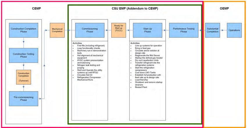
AUSTRALIA PACIFIC LNG PTY LIMITED
AUSTRALIA PACIFIC LNG PROJECT
COMMISSIONING AND START-UP ENVIRONMENTAL MANAGEMENT PLAN
“24. Before commencement the proponent must prepare a Construction Environmental
Management Plan (CEMP). The CEMP may be submitted in stages (Staged CEMP) in which
case commencement of a stage covered by the staged CEMP cannot commence until submitted
and approved by the Minister.
27. Before the commissioning of the first LNG train, an Operational Environmental Management
Plan (OEMP) must be prepared.
28. The OEMP must address the matters required to be included in the CEMP while
incorporating changes and any additions the proponent believes are necessary to reflect the shift
from the construction phase to the operational phase.
29. The OEMP must be submitted for the approval of the Minister. Commissioning of the first
LNG train must not occur without the approval in writing of the Minister. The approved plan must
be implemented.”
Note: To avoid doubt, if a condition of another approval held by the proponent requires a
Construction Environmental Management Plan and/or Operational Environmental Management
Plan, the proponent may simultaneously meet the relevant requirements of both conditions by
submitting a single plan
As the last phase (performance testing) covered by the CSUEMP is consistent with the definition of
commissioning in the EPBC Act approval, this CSUEMP has also been submitted in accordance with
conditions 28-29. The operations phase will be managed under a subsequent OEMP which will be
-3 shows the relationship of this plan to
submitted prior to the commencement of that stage. Figure 1
the existing approved CEMP.
It is important to note that CSU activities will be undertaken in parallel with ongoing construction
activities, which are described in the existing CEMP (APLN-000-EN-R01-D-10181). As such, the
scope of the CSUEMP is to address those activities and associated potential impacts that are in
addition to the previously described impacts associated with ongoing construction. This Plan builds
on the environmental management framework and is provided as an addendum to the CEMP and its
relevant Subplans. Therefore, both the CEMP and the CSUEMP will be relevant for the LNG facility
whilst CSU activities are being undertaken.
The CSU of the LNG facility can be broken down into a number of phases from construction of the
facility through to full operations as illustrated in Figure 1-3, with definitions and timing provided in
Table 1 -1.
The LNG facility is proposed to be constructed in two stages, the first stage consisting of two LNG
trains and the second stage consisting of the remaining two LNG trains.
301001-00752 - 00-EN-REP-0335 - APLN-000-EN-R01-D-25659
Rev 2 - 18-Dec-2014
Page 2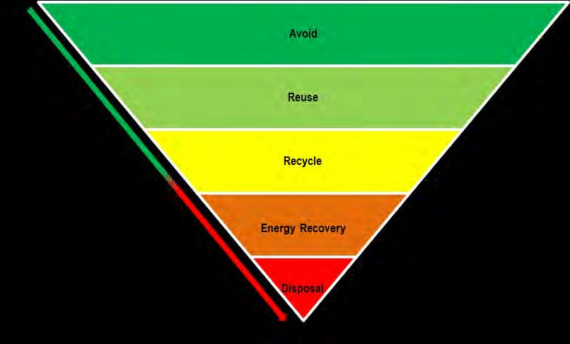
AUSTRALIA PACIFIC LNG PTY LIMITED
AUSTRALIA PACIFIC LNG PROJECT
COMMISSIONING AND START-UP ENVIRONMENTAL MANAGEMENT PLAN
Figure 1-1 LNG facility location
301001-00752 - 00-EN-REP-0335 - APLN-000-EN-R01-D-25659
Rev 2 - 18-Dec-2014
Page 3
AUSTRALIA PACIFIC LNG PTY LIMITED
AUSTRALIA PACIFIC LNG PROJECT
COMMISSIONING AND START-UP ENVIRONMENTAL MANAGEMENT PLAN
Figure 1-2 Matters of National Environmental Significance in relation to the stormwater outfalls and air emission release points
301001-00752 - 00-EN-REP-0335 - APLN-000-EN-R01-D-25659
Rev 2 - 18-Dec-2014
Page 4AUSTRALIA PACIFIC LNG PTY LIMITED
AUSTRALIA PACIFIC LNG PROJECT
COMMISSIONING AND START-UP ENVIRONMENTAL MANAGEMENT PLAN
Figure 1-3 Interaction between Construction, CSU and Operations EMPs
301001-00752 - 00-EN-REP-0335 - APLN-000-EN-R01-D-25659
Rev 2 - 18-Dec-2014
Page 5AUSTRALIA PACIFIC LNG PTY LIMITED
AUSTRALIA PACIFIC LNG PROJECT
COMMISSIONING AND START-UP ENVIRONMENTAL MANAGEMENT PLAN
Table 1-1 Definition of phases including Construction, CSU and Operations
Phase Description Train 1 Timing*
Construction During the Construction Phase, activities will include preparation Commenced – Q1,
of laydown and pre-fabrication areas and construction of access 2015
roads, LNG storage tanks, Train 1 and Train 2, utilities, marine,
and ancillary facilities. ‘Construction Completion’ is the stage
reached during the assembly of a system or the LNG facility
when the construction phase has been substantially completed
and the system or LNG facility is ready for a joint inspection.
Turnover Turnover is the milestone when the Construction Team hands Commenced – Q1,
control of a system or subsystem to the CSU Team. 2015
Construction, CSU and Australia Pacific LNG representatives will
conduct the joint inspection to develop a list of work to be
completed prior to Turnover, once all activities on the list are
completed, Turnover is achieved.
Pre-Commissioning Once construction is complete in a defined system, pre- Q4, 2014 – Q2, 2015
Commissioning activities will be undertaken by CSU. Pre-
Commissioning activities and tests ensure piping and component
post-construction cleanliness and confirm continuity and the
ability to withstand operating pressures and other operating
conditions prior to the introduction of process fluids and
hydrocarbon feed. Pre-Commissioning activities will include (but
not be limited to) valve testing, loop checking, motor run tests,
cleaning, flushing and first fill of lubrication systems, inspection
of vessels and pipework, pressure testing, and charging of
catalysts.
Mechanical The end of Pre-Commissioning activities is marked by Q4, 2014 – Q2, 2015
Completion Mechanical Completion which is the stage reached during the
assembly of a system when the Construction and Pre-
Commissioning phases have been complete and verified as
such, and the associated equipment, systems / sub-systems and
areas have been installed, inspected, and tested in accordance
with the approved design criteria.
Construction and Australia Pacific LNG representatives will
again conduct the joint walk-down to develop a list of work to be
completed.
Once Mechanical Completion of a system or subsystem has
been achieved, the CSU Team can commence Commissioning
activities.
Commissioning Commissioning work will be performed following Mechanical Q4, 2014 – Q2, 2015
301001-00752 - 00-EN-REP-0335 - APLN-000-EN-R01-D-25659
Page 6
Rev 2 - 18-Dec-2014AUSTRALIA PACIFIC LNG PTY LIMITED
AUSTRALIA PACIFIC LNG PROJECT
COMMISSIONING AND START-UP ENVIRONMENTAL MANAGEMENT PLAN
Phase Description Train 1 Timing*
Completion and before the introduction of process fluids.
Responsibility for Commissioning rests with CSU. The
Operations Team will work alongside the CSU Team in a
shadowing role whilst the CSU Team maintains responsibility for
a system or LNG facility Commissioning.
The Commissioning phase is focused on verification that a set of
components (or equipment) function as a complete system.
Ready for Start-Up RFSU occurs when all Construction of a system or the LNG Q3, 2015
(RFSU) facility is completed as designed, all Commissioning activities
have been carried out, and a system or the LNG facility is ready
to accept CSG. The CSU Team will take care, custody and
control after acceptance of RFSU.
Start-Up Start-Up is generally the introduction and processing of CSG. Q3, 2015
This phase includes dry out and cool-down of refrigeration,
cryogenic and LNG storage systems. Start-Up includes first ship
loading and ends with the completion of LNG facility
Performance Testing.
Performance Test A 72-hour Performance Test is conducted prior to achieving Q3 / Q4, 2015
substantial completion and hand over to operations. This marks
the end of the CSU Phase.
Operations All necessary systems, resources and requirements to operate After successful
the LNG facility are operational. completion of
Performance Test
Operations activities will be undertaken in accordance with the
Operational Environmental Management Plan (OEMP).
* The above timings are approximate. Timing for the equivalent Train 2 Phase will occur six to nine months after Train 1 with
timings for Train 3 and 4 are yet to be confirmed.
1.3 Structure and content
The CSUEMP is structured as follows, noting that the provision of information has been cross-
checked against EA Condition A12 requirements:
Section 1 provides contextual information including background details of the facility and the
scope in which this plan applies.
Section 2 describes the LNG facility facilities and CSU activities to which the CSUEMP applies
Section 3 provides the general environmental values of the site on which the LNG facility is
located, and its immediate surrounds.
301001-00752 - 00-EN-REP-0335 - APLN-000-EN-R01-D-25659
Page 7
Rev 2 - 18-Dec-2014AUSTRALIA PACIFIC LNG PTY LIMITED
AUSTRALIA PACIFIC LNG PROJECT
COMMISSIONING AND START-UP ENVIRONMENTAL MANAGEMENT PLAN
Section 4 describes the environmental management processes and actions that apply
specifically to each environmental aspect that may be impacted during CSU. Each section
addressing an environmental aspect includes a description of:
- site activities and potential environmental impacts associated with those;
- environmental protection objectives and targets; and
- control strategies, monitoring and reporting to ensure targets are achieved.
Section 5 describes general environmental management relevant to the CSU of the LNG facility.
These are the environmental management systems, processes and actions that are not specific
to any one particular environmental aspect.
1.4 Related documents
A number of management plans have been developed prior to the commencement of CSU to address
conditions of the EA and EPBC Act approval, as listed below:
CEMP (APLN-000-EN-R01-D-10181)
Acid Sulfate Soil Management Plan (APLN-000-EN-R01-D-10159)
Stormwater Management Plan (APLN-000-EN-R01-D-00077)
Biosecurity Management Plan (APLN-000-EN-R01-D-10175)
Fauna Management Plan (APLN-000-EN-R01-D-10180)
Vegetation Clearing Plan (APLN-000-EN-R01-D-10178)
Bushfire Management Plan (APLN-000-EN-R01-D-10174)
Mosquito and Midge Management Plan (APLN-000-EN-R01-D-10169)
Marine Mammal and Turtle Management Plan (APLN-000-NV-V01-D-10098)
Receiving Environment Monitoring Program (APLN-000-EN-V01-D-10160)
Greenhouse Gas Management Plan (APLN-000-EN-R01-D-10176)
Waste Management Plan (APLN-000-EN-R01-D-10167)
Species Management Program (APLN-000-EN-R01-D-10545)
Species Management Plan - Caspian Tern (Hydroprogne caspia) (APLN-000-EN-R01-D-10496)
Species Management Plan - Eastern Osprey (Pandion cristatus) (APLN-000-EN-R01-D-10494)
Species Management Plan - Eastern Reef Egret (Egretta sacra) (APLN-000-EN-R01-D-10498)
Species Management Plan - Fork Tailed Swift (Apus pacificus) (APLN-000-EN-R01-D-10499)
Species Management Plan - Rainbow Bee-eater (Merops ornatus) (APLN-000-EN-R01-D-10500)
Species Management Plan - Satin Fly Catcher (Myiagra cyanoleuca) (APLN-000-EN-R01-D-
10495)
301001-00752 - 00-EN-REP-0335 - APLN-000-EN-R01-D-25659
Page 8
Rev 2 - 18-Dec-2014AUSTRALIA PACIFIC LNG PTY LIMITED
AUSTRALIA PACIFIC LNG PROJECT
COMMISSIONING AND START-UP ENVIRONMENTAL MANAGEMENT PLAN
Species Management Plan - White-bellied Sea Eagle (Haliaeetus leucogaster) (APLN-000-
ENR01-D-10497)
Migratory Shorebird Management Plan (APLN-000-EN-R01-D-10438)
Water Mouse (Xeromys myoides) Management Plan (APLN-000-EN-V01-D-10644)
The following document may be read in conjunction with this Plan:
Construction Shipping Activity Management Plan (APLN-000-EN-R01-D-13916)
Joint Proponent Offsets Proposal (APLN-000-EN-R01-D-15326)
301001-00752 - 00-EN-REP-0335 - APLN-000-EN-R01-D-25659
Page 9
Rev 2 - 18-Dec-2014AUSTRALIA PACIFIC LNG PTY LIMITED
AUSTRALIA PACIFIC LNG PROJECT
COMMISSIONING AND START-UP ENVIRONMENTAL MANAGEMENT PLAN
2. Overview of LNG facility and CSU activities
2.1 LNG facility description
This section provides an overview of the function of each of the key units at the LNG facility including:
receiving and metering;
pre-treatment;
liquefaction, including support utilities;
flare and vent systems;
storage and loading; and
associated infrastructure including power generation and water management.
An overview of the LNG production process is provided in Figure 2-1, with a further description of the
processes provided below.
-1 Schematic of the Optimized Cascade® process
Figure 2
301001-00752 - 00-EN-REP-0335 - APLN-000-EN-R01-D-25659
Page 10
Rev 2 - 18-Dec-2014AUSTRALIA PACIFIC LNG PTY LIMITED
AUSTRALIA PACIFIC LNG PROJECT
COMMISSIONING AND START-UP ENVIRONMENTAL MANAGEMENT PLAN
Each LNG train will utilise two identical gas turbine driven propane compressor sets in parallel, two
identical gas turbine driven ethylene compressor sets in parallel and two identical gas turbine driven
methane compressor sets in parallel (i.e. six Gas Turbine Compressors (GT compressors) in total for
each train).
The layout of the LNG facility shown on Figure 2-2 highlights the relevant functional units.
301001-00752 - 00-EN-REP-0335 - APLN-000-EN-R01-D-25659
Page 11
Rev 2 - 18-Dec-2014AUSTRALIA PACIFIC LNG PTY LIMITED
AUSTRALIA PACIFIC LNG PROJECT
COMMISSIONING AND START-UP ENVIRONMENTAL MANAGEMENT PLAN
Figure 2-2 Layout of the LNG facility
301001-00752 - 00-EN-REP-0335 - APLN-000-EN-R01-D-25659
Page 12
Rev 2 - 18-Dec-2014AUSTRALIA PACIFIC LNG PTY LIMITED
AUSTRALIA PACIFIC LNG PROJECT
COMMISSIONING AND START-UP ENVIRONMENTAL MANAGEMENT PLAN
2.1.1 Recei vi ng and metering
CSG is delivered by pipeline to the LNG facility site where it is split and metered, via an inlet
separator, into three streams:
two feed gas streams to the liquefaction process; and
one medium pressure fuel gas stream to fire the gas turbine generators (GTGs).
2.1.2 Pre-treatment
Acid gas removal
Feed gas from the inlet separator is directed to the acid gas removal unit (AGRU), where carbon
dioxide (CO2) and trace amounts of hydrogen sulphide (H2S) (known as acid gases) are removed
using an activated amine solution to eliminate potential freezing and meet LNG specifications.
The system consists of an absorber, a regenerator and associated equipment. Feed gas enters the
bottom of the absorber and is contacted with the amine (which flows down from the top). The CO 2 and
sulphur contaminants in the gas absorb into the amine to leave a sweet natural gas stream exiting the
top of the absorber.
The 'rich' amine solution containing the contaminants leaves the bottom of the absorber and is fed to
the stripping section of the regenerator. Acid gas and water vapour are stripped out and form the
regenerator overhead vapour leaving a 'lean' amine solution, which is returned to the top of the
absorber. The regenerator overhead vapours are partially condensed and water is returned to the
regenerator and absorber. The acid gas, which is mainly CO2 with traces of H2S, is incinerated to
allow conversion of any H2S in the gas to sulphur dioxide (SO2) and convert any traces of methane
(CH4) to CO2 before being released to atmosphere.
Dehydration
Treated feed gas leaving the AGRU is chilled prior to entering the dryer inlet separator for separation
of any condensed hydrocarbons and water. Residual traces of water vapour are removed from the
feed gas to prevent the formation of ice crystals in the gas during liquefaction, and are retained within
molecular sieve dehydrators.
The dryers are regenerated by back-flowing clean, dry feed gas (heated using waste heat from
methane GT compressor exhaust). The adsorbed water is stripped off the bed together with some
CO2 and heavy hydrocarbons (if present), restoring the adsorption capacity of the molecular sieve.
The hot, wet regeneration gas leaving the dehydrator is cooled and passes to a knock out drum
where the condensed water is separated and sent to the water degassing drum. The regeneration gas
is re-circulated and combined with fresh feed gas upstream of the AGRU. The dry feed gas from the
dehydrators is then passed through after filters.
Mercury removal
The mercury removal beds contain special sulphur impregnated activated carbon. This final feed gas
treatment step removes any trace amounts of mercury to prevent potential damage to downstream
301001-00752 - 00-EN-REP-0335 - APLN-000-EN-R01-D-25659
Page 13
Rev 2 - 18-Dec-2014AUSTRALIA PACIFIC LNG PTY LIMITED
AUSTRALIA PACIFIC LNG PROJECT
COMMISSIONING AND START-UP ENVIRONMENTAL MANAGEMENT PLAN
heat exchangers. At this point the gas is very dry and free of impurities and will be sent to the
liquefaction section of the LNG facility.
The activated carbon bed has the capacity to last for at least three years before the carbon needs to
be replaced. Spent carbon, containing mercury, will be managed as a regulated waste.
2.1.3 Liquefaction
The dry feed gas is fed to the refrigeration systems where it is liquefied into the LNG product through
a combination of refrigerant heat exchangers and pressure reduction. This liquefaction system
consists of three refrigeration services being propane, ethylene and methane. The refrigerant
compressors and are equipped with dry low emissions technology.
Each refrigeration compressor is equipped with individual suction drums and anti-surge control
system. Inlet air to turbines is chilled to reduce the effect of ambient temperature.
The LNG product is pumped to the LNG storage tanks. Boil-off gas from the LNG tanks is
compressed and returned to the liquefaction system.
Liquefaction process utilities
A number of utilities provide support to the liquefaction process as detailed below:
Refrigerant storage for propane and ethylene.
Propane dehydration and mercury removal system used to purify propane stored at site for use
in the liquefaction process.
A closed loop, hot oil system provides the LNG facility's process heating requirements. Waste
heat from the ethylene compressors’ gas turbine exhausts is recovered to heat the oil. A gas-
fired auxiliary hot oil heater (AHOH) is provided for Start-Up and as a backup to a waste heat unit
for each LNG train. The AHOH normally operates with only pilots on (stand-by).
A closed circuit cooling water system cools lube oil from the refrigeration compressors and
turbines.
Electric motor-driven air compressor packages supply utility air, instrument air, and feed air to the
nitrogen generation system.
The two LNG trains share common back-up facilities which include 2 x 50% electric motor-driven
Auxiliary Air Compressors and a 50% diesel-driven Auxiliary Air Compressor (the latter is
capable of supplying black start and essential user plant and instrument air demand).
Nitrogen is used as blanket gas for selected storage tanks and as a purge gas. Nitrogen gas is
generated by membrane type, nitrogen generation units. A liquid nitrogen back-up system is also
provided.
Nitrogen is removed from the feed gas stream using a dedicated cryogenic nitrogen rejection unit
(NRU). Any traces of CH4 in the nitrogen stream are converted to CO2 in the NRU Thermal
Oxidiser before being vented to atmosphere, and is vented via a thermal oxidiser to burn traces
of methane and reduce greenhouse gas emissions.
301001-00752 - 00-EN-REP-0335 - APLN-000-EN-R01-D-25659
Page 14
Rev 2 - 18-Dec-2014AUSTRALIA PACIFIC LNG PTY LIMITED
AUSTRALIA PACIFIC LNG PROJECT
COMMISSIONING AND START-UP ENVIRONMENTAL MANAGEMENT PLAN
A fuel gas system provides high pressure (HP) fuel gas for the GT compressors, and low
pressure (LP) fuel gas for the incinerators and oxidisers, the AHOHs, flare pilots and header
sweeps and blanket gas for selected applications. The HP and LP fuel gas comprises of a mix of
approximately 90% dry treated feed gas and approximately 10% CSG from the pipeline.
Air inlet chilling is used for the main refrigeration compressor turbines to lower the temperature of
air entering the engine to enhance turbine performance in warmer weather and to optimise
efficiency. A standard propane refrigeration circuit cools a water / denatured ethanol mix, which
in turn is used to cool the turbine inlet air.
2.1.4 Flare and vent s yst em
The flare system acts as a vapour relief system and is the central safety feature of the LNG facility.
The flare system collects and disposes of hydrocarbon-containing streams which are typically
released during start-up, shutdown and equipment preparation for maintenance, but also during upset
and emergency conditions. These streams are disposed of by flaring. The design of the flares has
been based on expected abnormal conditions for each stream.
There are three flare systems within each of the three ground flares:
wet flare;
dry flare; and
marine flare.
The wet flare system disposes of warm hydrocarbon streams that may be saturated with water vapour
and / or contain free liquid hydrocarbons and water. These streams are mainly generated by relief
valve and start-up or shutdown control discharges from the process vessels. The dry flare system
handles cryogenic hydrocarbons (both vapour and liquid). The marine flare handles any LNG vapours
generated during loading of LNG product to the ship's storage tanks and from LNG storage tank and
boil-off gas systems. Boil-off gas compression limits the amount of flaring required during loading of
LNG, returning gas which would otherwise be flared to the liquefaction section of the LNG facility. The
flare enclosures are located in a safe area away from the process LNG facilities and LNG storage
tanks.
The flare system has been constructed as a ground flare, which provides reduced visibility and is
surrounded by a radiation fence 18.3m in height. The radiation fence height is designed on the basis
of being above the top of the burner flames at maximum flaring and controls heat and flame visibility.
2.1.5 LNG storage and loading
3
Two LNG storage tanks, each with a capacity of approximately 160,000m , a diameter of
approximately 86.6m and a height of approximately 32.1m, store the LNG product from trains 1 and 2.
The LNG Storage Tanks are a full-containment type comprising a 9% nickel steel inner container and
a prestressed-concrete outer container with a carbon steel lining. The LNG storage tanks are
designed and tested to meet requirements of the National Fire Protection Association standard for the
production, storage, and handling of LNG (NFPA 59A) and relevant Australian standards.
301001-00752 - 00-EN-REP-0335 - APLN-000-EN-R01-D-25659
Page 15
Rev 2 - 18-Dec-2014AUSTRALIA PACIFIC LNG PTY LIMITED
AUSTRALIA PACIFIC LNG PROJECT
COMMISSIONING AND START-UP ENVIRONMENTAL MANAGEMENT PLAN
Each LNG storage tank is equipped with loading pumps, level gauges, level transmitters, relief valves,
vents, temperature elements, and other basic instrumentation.
3
The ship loading facility currently allows for loading of LNG ships ranging in capacity from 125,000m
3
to 220,000m .
The LNG product is pumped from the LNG storage tanks to the jetty via a loading line, and transferred
to the ship via loading arms. A vapour recovery system captures boil-off vapour from the LNG storage
tanks, the chilled LNG loading lines and that generated during ship loading, and returns these to the
liquefaction section of the LNG facility.
It is expected that all boil-off gas generated during ship loading can be returned to the production
process; however, depending on the thermal condition of the ship upon arrival and ship’s vapour
composition, some may be directed to the marine ground flare.
2.2 Associated infrastructure
2.2.1 Pow er generation
The LNG facility utilises CSG for power generation in order to be self-sufficient in power requirements.
Electrical power is generated onsite using Solar Titan 130 GTGs to supply LNG processing and the
common utility and off-facility areas. Seven Solar Titan 130 GTGs are utilised for the two train facility.
The Solar Titan 130 GTGs are International Organisation for Standardisation (ISO) rated at 15MW
each and are equipped with low emissions combustion technology SoLo Nitrogen Oxides (NOx)
technology.
In addition, two low sulfur diesel powered generators are installed to provide emergency / standby
power. The diesel required to power the standby generators and firewater pumps is stored in a 40KL
double walled tank. Dedicated battery systems are provided where continuous power supply is
essential. These systems will service the permanent Facility and will be in operation during CSU.
2.2.2 Water suppl y
Potable water is supplied to site via the Gladstone Area Water Board (GAWB) pipeline and is used to
provide water for construction and CSU activities. Potable water is used for drinking, as site utility
water and for firewater.
Potable water is converted to demineralised water via a two-stage Reverse Osmosis (RO) Unit for
turbine wash, the inlet air chilling system and the make-up to the AGRU, all of which require stringent
water quality. Demineralised water reject will be transferred to the sewage storage tank and pumped
to the Gladstone Regional Council (GRC) sewer system.
2.2.3 Stormw ater
A stormwater management system was installed as part of the construction phase. The system is
designed to separate clean from potentially contaminated stormwater streams. Off-site stormwater is
prevented from entering the site footprint through the installation of two clean water diversion drains
(Northern and Southern) which flow directly to Outfalls 1 and 4. Stormwater which falls onsite is
conveyed by internal rock lined drainage channels to one of the six sediment basins which allow
301001-00752 - 00-EN-REP-0335 - APLN-000-EN-R01-D-25659
Page 16
Rev 2 - 18-Dec-2014AUSTRALIA PACIFIC LNG PTY LIMITED
AUSTRALIA PACIFIC LNG PROJECT
COMMISSIONING AND START-UP ENVIRONMENTAL MANAGEMENT PLAN
suspended sediments to settle and filter any gross pollutants. The sediment basins are discharged
through Outfalls 1 to 4 as described in Table 2-1. An overview of the stormwater management
system, including clean water diversion drains, internal drainage system, sediment basins and outfall
locations is included in Figure 2-3.
.
Table 2-1 Stormwater release points
Release Latitude or Longitude or Description of Receiving Water
Point northing (GDA94) easting (GDA94) Description
Release Point
RP3 7,372,021N 314,452E Stormwater Outfall 1 Port Curtis
RP4 7,371,781N 315,133E Stormwater Outfall 2 Port Curtis
RP5 7,370,877N 315,288E Stormwater Outfall 3 Port Curtis
RP6 7,370,774N 315,449E Stormwater Outfall 4 Port Curtis
Further detail regarding the design, management and monitoring of stormwater to achieve the quality
characteristics outlined in the EA, is provided in the CEMP and included in section 4.3.
301001-00752 - 00-EN-REP-0335 - APLN-000-EN-R01-D-25659
Page 17
Rev 2 - 18-Dec-2014AUSTRALIA PACIFIC LNG PTY LIMITED
AUSTRALIA PACIFIC LNG PROJECT
COMMISSIONING AND START-UP ENVIRONMENTAL MANAGEMENT PLAN
Figure 2-3 Stormwater management system overview
301001-00752 - 00-EN-REP-0335 - APLN-000-EN-R01-D-25659
Page 18
Rev 2 - 18-Dec-2014AUSTRALIA PACIFIC LNG PTY LIMITED
AUSTRALIA PACIFIC LNG PROJECT
COMMISSIONING AND START-UP ENVIRONMENTAL MANAGEMENT PLAN
2.2.4 Potentiall y contami nated stormw ater
Prior to commissioning of the potentially contaminated stormwater system, the transportation,
handling, storage, use, disposal and spill clean-up of any hydrocarbons and chemicals onsite will be
in accordance with the CEMP and section 4.4 and 4.5 of this document. During CSU two contaminant
streams have been identified in addition to those already discussed in the CEMP. Once
commissioned, these systems will operate as discussed below.
The system is designed such that any stormwater that falls within the process area and that has the
potential to be contaminated with hydrocarbons or chemicals is collected in either internal bunds or
containment sumps.
In the case of potential hydrocarbon contamination the bund/sump content is analysed for
hydrocarbons and pumped to either the wastewater treatment system if contaminated or discharged
to the site stormwater management system if not contaminated.
The wastewater treatment system includes a Corrugated Plate Interceptor (CPI) Oil/Water Separator
and various holding tanks. The CPI separator is an above ground unit designed to separate free oil
and solids from the process wastewater and contaminated stormwater by directing wastewater flow
through parallel corrugated plates installed in packs. Accumulated oil is pumped to the waste oil tank
where it is held to facilitate further separation. Sampling ports at four different elevations are used to
determine the water and oil interface. Water is drained via the draw-off nozzle and routed to the waste
oil tank oily water lift station and pumped back to the CPI separator. Waste oil from the tank is
removed periodically for approved off-site disposal. Concrete curbing is provided around the Waste
Oil Tank to contain spills. Solids and sludge that settle to the bottom of the CPI are pumped to a
sludge holding tank, from which sludge will be periodically removed by waste trucks for approved off-
site disposal.
Treated effluent from the CPI separator is pumped to the CPI effluent holding tank for storage and
from here the effluent can be pumped to the sewage storage tank or back to the CPI depending on
the oil concentration.
Stormwater that may be potentially contaminated with amine will be collected in the amine bund. From
here the water will be sent to the waste water tank or removed by waste truck for approved off-site
disposal.
2.2.5 Wastew ater
During construction and CSU any sewage produced will be transferred from the collection tanks
onsite to the GRC sewage pipeline. Once the permanent buildings are operational, sewage will be
conveyed through underground pipes by gravity to sewage lift stations. Grinder pumps will then
transfer the sewage to a storage tank which is pumped to the GRC sewer system.
During CSU, additional contaminated wastewater will be generated as a result of equipment cleaning
and flushing. This water will be transferred to either the waste water tank or the sewage storage tank,
subject to approval, or removed by waste truck for approved off-site disposal.
Condensate water will also be generated from the Inlet Air Chilling Unit. This unit is provided to chill
the ambient air feed to each of the compressor turbine drivers. Depending on the ambient conditions,
301001-00752 - 00-EN-REP-0335 - APLN-000-EN-R01-D-25659
Page 19
Rev 2 - 18-Dec-2014AUSTRALIA PACIFIC LNG PTY LIMITED
AUSTRALIA PACIFIC LNG PROJECT
COMMISSIONING AND START-UP ENVIRONMENTAL MANAGEMENT PLAN
moisture from the air will condense on the coils and will be captured in collection pans. During the
CSU phase this clean water is then sent to the internal drainage channel for storage in Sediment
Basin 2 prior to use for construction purposes.
2.3 General Commissioning activities
General Commissioning phase activities that will be undertaken include:
loading of catalysts, absorbents and desiccants;
first fills of process chemicals (including refrigerant) to storage vessels and amine;
vessel final internal inspection and closure;
loop functionality checks (further verification of proper operation of control loops);
machinery run-in demonstration tests, including uncoupled operation of equipment (fan/pump
motors, etc.) and demonstration tests (to check bearing, vibration, operation of meter, etc.);
hot alignment of mechanical equipment, including coupled operation and testing;
Heating, Ventilation and Air Conditioning (HVAC) system pressurisation and balancing;
Inert gas and nitrogen leak testing; and
start and operate the utility systems up until RFSU.
Prolonged circulation testing will be undertaken, which will include the circulation of lube oil through
systems, checking the operation of components and cleanliness. The lube oil system flushing will be
performed by circulating mineral or synthetic oil through each piece of equipment, using external
filters, heaters, pumps and moisture removal equipment.
Completion of cleaning and checking will include checking temporary strainers and differential gauges
during initial circulation or flow of liquids and degreasing, cleaning and chemical treating (e.g. pickling)
of systems. Some pipework and equipment will require chemical cleaning which involves the
circulation of chemicals (diluted in a solution). If required, cleaning solutions may be heated using
vendor supplied heaters or the AHOH.
During commissioning activities the fuel gas to the GTG’s, liquefaction gas turbine drivers, AHOHs,
AGRU incinerators, NRU thermal oxidizers and flare pilots will be 100% pipeline gas.
During commissioning activities water use is expected to be associated with AGRU system cleaning,
initial filling of the amine surge tank, inlet air chilling system and closed circuit cooling water system.
Liquid effluents generated through cleaning during Commissioning, such as lube oils, chemicals and
flushing solutions will be collected and removed for approved off-site disposal.
Where temporary ablutions are required for Commissioning personnel, these will be managed in
accordance with the CEMP.
Further detail regarding Commissioning phase activity relevant to specific LNG facility process areas
and potential impacts discussed in this Section is provided below.
301001-00752 - 00-EN-REP-0335 - APLN-000-EN-R01-D-25659
Page 20
Rev 2 - 18-Dec-2014AUSTRALIA PACIFIC LNG PTY LIMITED
AUSTRALIA PACIFIC LNG PROJECT
COMMISSIONING AND START-UP ENVIRONMENTAL MANAGEMENT PLAN
2.4 LNG facility component-specific Commissioning activities
2.4.1 AG RU cleaning system
Degreasing of the AGRU will be done by circulating clean demineralised water at ambient
temperature throughout the liquid system to remove the bulk of dirt, loose scale, slag and debris. The
system will then be flushed with a three percent Potash Solution. After flushing with Potash solution,
the system will be rinsed with demineralised water. Cleaning solutions will be heated using the AHOH.
2.4.2 GT compressors
During Commissioning, the principal contractor may fire each compressor gas turbine driver briefly to
validate ignition turn-over and undertake mechanical run-ins.
2.4.3 AHOHs
Operation of AHOHs is necessary for process heating requirements for the fuel gas system. As such
the AHOH will be commissioned and tested and then operated at partial load thereafter for fuel gas
heating.
If a vendor supplied heater is not available for the chemical cleaning of the AGRU system, then the
AHOHs will be run over several days to supply heat for this process.
2.4.4 Flare and vent s yst ems
Prior to the Commissioning of the flare system, it is expected that temporary controlled venting will be
required primarily to remove nitrogen purge gas from piping. Venting will be via a suitable release
point, and will be directed vertically upwards without any impedance or hindrance. Once the flare
system is commissioned it is expected that flaring will occur intermittently during Commissioning. This
is a normal and expected component of CSU.
2.4.5 GTGs
Sequential Commissioning of the GTGs will be undertaken over an extended period of time in
preparation for the Commissioning of the first LNG Train. This will involve the introduction of pipeline
gas into the fuel gas system where free liquids are removed, particulates are filtered and the supply is
heated prior to entering the GTGs. Utility systems such as instrument/plant air, nitrogen, and firewater
will be partly commissioned to support this program.
Until Commissioning of the first LNG train commences the GTG units will be idling on part load or
non-operational. Given that only one to two GTG units will be operational at any point in time during
Commissioning, it is expected that emissions will be well below operational emissions.
2.4.6 General Start-Up activities
On successful completion of all CSU activities will commence including:
full function emergency shutdown system test;
pre-Start-Up safety review;
301001-00752 - 00-EN-REP-0335 - APLN-000-EN-R01-D-25659
Page 21
Rev 2 - 18-Dec-2014AUSTRALIA PACIFIC LNG PTY LIMITED
AUSTRALIA PACIFIC LNG PROJECT
COMMISSIONING AND START-UP ENVIRONMENTAL MANAGEMENT PLAN
introduction of feed gas (noting fuel gas already introduced for power generation to support
Commissioning of electrical systems);
amine system circulation;
regeneration system on-line for molecular sieves;
defrost gas header on-line;
introduction of operating fluids and feed stocks to the various units and conducting circulating
cleanliness checks, purging of inert gas with feed gas and cleaning and checking temporary
strainers as required;
drying out of liquefaction units;
refrigerant introduction and compressor start-up;
cool down of liquefaction equipment, piping, storage tanks and loading systems to make ready to
safely handle LNG and propane without thermal shock or stress due to uneven temperature
gradients;
dry out, purge and cool down LNG tank;
ramp up to full production with feed rate up to design, then line-out;
load first LNG ship; and
set up and conduct performance tests to demonstrate all equipment and systems meet required
design parameters.
Once LNG production is underway the fuel gas to the liquefaction gas turbine drivers, AHOHs,
incinerators, oxidisers and flare pilots will comprise of 90% dry treated feed gas (downstream of the
amine unit) and 10% pipeline gas. The fuel gas to the power gas turbine generators will continue to
be 100% pipeline gas.
Water use during Start-Up is expected to be makeup water to the acid gas removal unit, inlet air
chilling system and the closed circuit cooling water system.
Further detail regarding Start-Up phase activities relevant to specific LNG facility process areas and
potential impacts is provided below.
2.5 LNG facility component-specific Start-Up activities
2.5.1 AG RU incinerator and NRU -thermal oxi diser
For both the AGRU Incinerator and NRU-Thermal Oxidiser during Start-Up phase the ignition of pilots
will occur on commencement of LNG production to treat waste streams. Both will be run at varying
rates to match the contaminant load associated with the composition of incoming gas and operating
rates.
301001-00752 - 00-EN-REP-0335 - APLN-000-EN-R01-D-25659
Page 22
Rev 2 - 18-Dec-2014You can also read