48-Volt Electrical Systems- A Key Technology Paving to the Road to Electric Mobility - Zvei
←
→
Page content transcription
If your browser does not render page correctly, please read the page content below
48-Volt Electrical Systems –
  A Key Technology Paving to the Road
                   to Electric Mobility

     German Electrical and Electronic Manufacturers’ Association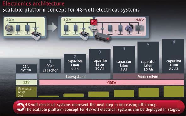
48-Volt Electrical Systems –
A Key Technology Paving the Road to Electric Mobility

Published by:
ZVEI - German Electrical and Electronic
Manufacturers’ Association
Electronic Components and Systems and
PCB and Electronic Systems Divisions
Lyoner Strasse 9
60528 Frankfurt am Main, Germany

Phone: +49 69 6302-276
Fax: +49 69 6302-407
E-mail: zvei-be@zvei.org
www.zvei.org

Responsible:
Hans-Martin Fischer, ZVEI
Dr. Reiner Korthauer, ZVEI

Authors:
Jürgen Bilo, Continental
Dr. Heinz-Georg Burghoff, Horegulus Consulting
Humberto dos Santos, TDK Europe
Jürgen Engbring, Leoni Bordnetz Systeme
Edmund Erich, Delphi
Peter Gresch, OptE GP Consulting
Frank Harrmann, Leoni Kabel
Dr. Thomas Heckenberger, Mahle Behr
Norbert Hees, Kostal
Istvan Hegedüs-Bite, ZF Friedrichshafen
Dr. Helmut Kalb, Leoni Kabel
Dr. Matthias Kriegel-Gemmecke, NSG
Dr. Christian Kuper, Johnson Controls
Antonio Leone, Freescale
Dr. Marc Nalbach, Hella
Bernd Piller, Continental
Hans Rechberger, Webasto
Norbert Schnocks, Continental
Richard Schöttle, Robert Bosch
Hans-Joachim Schröder, Brose
Ulrike Sinner, Valeo
Waldemar Stabroth, TE Connectivity
Joachim Weitzel, Infineon
Michael Günther Zeyen, vancom

April 2016

While every care has been taken to ensure the accuracy of this document,
ZVEI assumes no liability for the content. All rights reserved. This applies in
particular to the storage, reproduction, distribution and translation of this
publication.
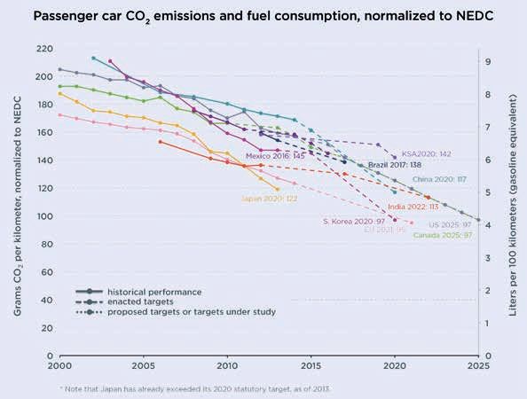
Table of Contents

             1. Introduction                                               4
               1.1 CO2-limits: the discussion and results                  5
               1.2 A look back at the debate on 42-volt systems in 2000    6
               1.3 The market for hybrids – issues and trends              7
               1.4 Economic context                                        9
               1.5 VDA Recommendation 320                                 10
               1.6 Additional technical challenges                        11

             2. Architectures                                             15
               2.1 Powertrain                                             15
               2.2 Types of electrical system topologies                  17

             3. Components                                                19
               3.1 Generators and motors                                  19
               3.2 Heaters and additional heating systems                 20
               3.3 Air-conditioning compressors                           21
               3.4 Pumps		                                                22
               3.5 Windshield defrosters                                  22
               3.6 Chassis functions                                      24
               3.7 Fan motors                                             25
               3.8 Connecting systems                                     26
               3.9 Wiring harnesses                                       27
               3.10 Inverters                                             28
               3.11 DC/DC converters                                      28
               3.12 Energy and battery management                         29
               3.13 Active electronic components                          30
               3.14 Passive components                                    33

             4. Summary and Outlook                                       36

             5. List of Abbreviations                                     37

                                                                               3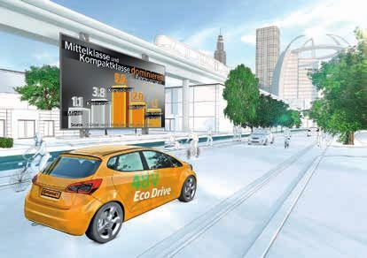
1. Introduction
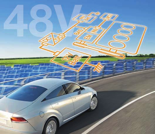
The automotive industry can only barely con- The new 48-volt voltage level (figure 1) opens
tinue or no longer meet the challenge pre- up more cost-effective opportunities for
sented by the CO2 targets defined by the Euro- hybridisation. The development of these mul-
pean Commission purely by improving standard tiple-voltage architectures in vehicles requires
internal combustion engine technology. Alter- detailed investigation at both the systems and
native drive concepts that make it possible to components levels.
drastically reduce average fleet CO2 emissions
will need to be deployed. As part of this process, a third voltage level of
48 volt has been defined to supplement the
While today’s hybrid vehicles meet this techni- voltage levels of 12/24 volt and high-voltage (>
cal criterion, they are not yet available at suf- 60 volts). The primary purpose of this new volt-
ficiently attractive price points. This is, above age level is to reduce CO2 emissions by means
all, due to the high cost of meeting the safety of recuperation and start-stop features and to
requirements that arise as a consequence of the power electrical components classed as high-
electric drive function in these vehicles being power loads (such as air-conditioning compres-
realized using voltages in excess of 60 volts (the sors, electrical heaters, pumps and steering
maximum permissible contact voltage). drives). Over and above this, the deployment of
48-volt technology providing additional torque
Architecture: enables more dynamic handling and perfor-
mance (a “boost” effect).
Functionality E - Boost Extended
12V - 48V
Power per Function
Base Architecture Requirements
Up to 12 kW
0.5 kW to 5 kW
DC / DC Inverter
12 V
Battery 12V Load
48 V
M/G
Battery
Active Chassis
ACC Electric Steering
Air Condition HWS
PTC Air Condition
Cooling
B
Engine
S Motor
G Engine Cooling
Inverter
DC / DC
EPS Heated Windscreen
48V
12V Battery
Battery PTC Heater
E - Turbo Charger
Figure 1: Base architecture – source: Delphi
4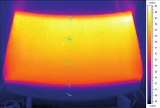
1.1 CO2-limits: the discussion and results                               “Transport accounts for approximately 26 per
In many countries around the world, attempts                             cent and thus for a significant portion of total
are being made to regulate the CO2 emissions                             CO2 emissions in the EU. Car traffic, with a total
of road transport (figure 2). While the current                          share of approximately 12 per cent, is responsi-
absolute limits set for cars vary from region to                         ble for almost half of these emissions.”1 From
region, all locales demand substantial reduc-                            2021 on, all newly registered passenger cars
tions over the coming years.                                             in Germany will be subject to a limit value of
                                                                         95 g CO2 per km. That corresponds to an aver-
                                                                         age fuel consumption rate of about 58.8 mpg
                                                                         (gasoline engines) or 65.3 (diesel). Further
                                                                         reductions in the years after 2021 are under
                                                                         discussion. From 2050 on, new cars should not
                                                                         emit any CO2 at all. The European regulations
                                                                         take account of the weight of vehicles. The limit
                                                                         value of 95 g CO2/km applies only to vehicles
                                                                         with a “standard weight” of 1,350 kg. Heavier
                                                                         vehicles may emit somewhat higher levels of
                                                                         CO2, while lighter vehicles must emit less.

Figure 2: International CO2 targets – source: The International Council for Clean Transportation

                                                                                                                              5
The automotive industry has to make consid-         Initially, several arguments seemed to come
    erable efforts to meet both the limit values        down in favour of the new system: power con-
    currently defined and those that will apply         sumption and demand were continuing to
    in the future. All stakeholders are aware that      rise, a need for higher-powered generators to
    actions focusing solely on enhancing the effi-      meet this increase in demand was perceived,
    ciency of the IC engine will not be sufficient.     and in the rationale of the time, higher volt-
    Additional measures are necessary to reach the      ages offered the only chance of achieving this.
    target. These include improved aerodynam-           Power requirements of well over one kW – for
    ics, lightweight design, low rolling resistance     solenoid valve control, for example – could not
    tires, LED lighting, more efficient transmis-       be realised by 12-volt systems, even when only
    sions (automatic dual-clutch transmissions)         needed very briefly. Finally, the need to intro-
    and the electrification of auxiliary components.    duce start-stop systems driven by environmen-
    Water pumps and air-conditioning compressors        tal regulations geared to reducing emissions
    can, for example, be driven electrically and at     was also a factor, as were the weight decreases
    speeds dictated by current requirements rather      achievable through the smaller cross-sectional
    than directly from IC engines.                      area of cables in 42-volt systems.

    The introduction of a 48-volt starter generator     In the further course of the 90s, this solution
    to make a “boost and coast” function possible       was not phased in on a widespread basis, apart
    and allow considerably enhanced recuperation        from two car models in Japan and the US, as the
    vis-à-vis 12-volt systems is particularly attrac-   increased costs associated with the new system
    tive.                                               were not matched by functional benefits. In the
                                                        interim, generator sizes of 3 kW and higher had
    1.2 A look back at the debate on 42-volt            come to the market for 12-volt systems, while
    systems in 2000                                     systems with extremely high energy demand
    At the beginning of the 90s, as the advanced        were not realised. Solenoid valve control, for
    development departments of major vehicle            example, was not introduced. Start-stop sys-
    manufacturers were evaluating the advantages        tems integrated into 12-volt systems gained
    of higher-voltage systems, the international        ground. It seemed that higher voltages were no
    42-volt consortium was founded providing a          longer going to be needed.
    forum for discussions between automobile man-
    ufacturers and suppliers. At the time, a 42-volt    The 48-volt debate which took off in 2011 may
    system was being debated as a replacement for       seem superficially similar to this earlier discus-
    conventional 12-volt systems. What was termed       sion, but the approach now being pursued sets
    a 42-volt system was effectively a 36-volt sys-     different priorities. 48-volt on-board power sys-
    tem with a 36-volt battery - and therefore three    tems (48 volts = four times the nominal voltage
    times the voltage of conventional 12-volt sys-      of 12-volt systems) are being championed as
    tems. This voltage (36/42 volts) was chosen with    a supplement to 12-volt systems and not as a
    the aim of ensuring that voltage in on-board        replacement for them. The contact protection
    power systems would never exceed 60 volts           limit of 60 volts is, however, also of critical
    after all tolerances had been factored in, since    importance today.
    this would avert the need for costly contact
    protection. The new on-board power system
    was, however, named for the charging voltage
    rather than the battery voltage in order to lend
    emphasis to the innovative nature of the new
    solution.

6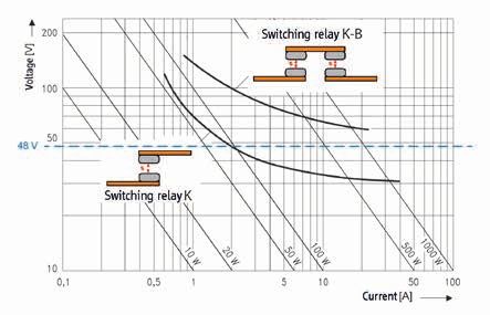
The chief motivation for introducing an addi-                            At this point, most European automotive man-
tional vehicle electrical system voltage at                              ufacturers have already decided to introduce
this point in time can be identified in the                              48-volt technology to reduce the consumption
above-mentioned EU regulations specifying                                of their fleets and meet the new European CO2
an average limit value of 95 g CO2/km for pas-                           limits applicable from 2021 on (figure 3).
senger cars from 2021 on. The threat of finan-
cial penalties for exceeding these new limit
values justifies the deployment of relatively
costly measures. 48-volt systems make it pos-
sible to build on start-stop systems to develop
mild hybrids with remarkable recuperation and
“boost and coast” features. This leads to a drop
in energy consumption and emissions that can
stretch into two-digit percentages.

Figure 3: Scalable platform concept for introducing 48-volt electrical systems – source: Audi

1.3 The market for hybrids –                                             hybrids has emerged. In China, however,
issues and trends                                                        all-electric vehicles are particularly in demand.
While the cost-benefit calculations of the major-                        48-volt systems still have their development
ity of car buyers still do not seem to be tipping                        nucleus in Europe, although their advantages
in favour of hybrids, the question remains, as                           have now been recognised by many automotive
to how the electrification of the powertrain as                          manufacturers and global programs have been
a mass-market technology could contribute to                             started accordingly.
reducing CO2 emissions.
                                                                         With an eye to avoiding high investment costs,
In the foreseeable future, start-stop systems,                           minimising complexity and facilitating easier
48-volt systems and high-voltage electrifica-                            maintenance, emphasis is largely being placed
tion will all exist alongside one another in most                        on finding simple solutions that are easy to
fleets. A strong global trend towards plug-in                            integrate. This applies, in particular, to the
                                                                                                                             7
high-volume market for compact and mid-size             This allows the implementation of many func-
    cars (figure 4), which is subject to strong cost        tions familiar from hybrid systems with signif-
    pressures. In the most basic case, the alternator       icantly higher voltages. Where high-voltage
    is replaced with a belt-driven starter generator        hybrids allow CO2 emissions reductions of about
    (BSG) that operates more efficiently at 48 volts        20-25 per cent (CO2/km), initial results suggest
    and starts the IC engine extremely rapidly and          that 48-volt mild hybrids can achieve reductions
    with minimal noise and vibration. Electric assist       of 10-15 per cent in per-km CO2 emissions. A
    boosts the responsiveness of the IC engine by           comparison of the extra costs shows that the
    supplying extra power in specific driving situa-        48-volt mild hybrids are only 30-50 per cent as
    tions. This allows additional torque to be mobi-        cost-intensive as high-voltage hybrids. As such,
    lised. In general, the 12-volt starter battery is       the 48-volt system represents an intelligent
    supplemented with a 48-volt battery that is             and, in particular an affordable supplement to
    charged via the BSG in recuperation mode dur-           full and plug-in hybrids. Furthermore 48-volt
    ing deceleration phases.                                systems can more easily be integrated into
                                                            existing vehicle powertrains and architectures –
                                                            fewer extensive modifications are required. As
                                                            such, it can be expected that the 48-volt volt-
                                                            age level will rapidly become established in the
                                                            market.

                                              Figure 4: Mid-sized and compact cars are the volume drivers – source: Continental

8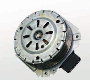
In addition to the benefits of hybridisation, the                                      Market forecasts predict that 25 per cent of
additional 48-volt system also makes it pos-                                           newly registered cars will have an electrified
sible to operate a selection of electrical com-                                        powertrain by 2025 (figure 5) and that almost
ponents in the vehicle at higher voltages. This                                        half of these will feature 48-volt technology.
is significant because the number of electrical                                        From the year 2020 onwards, global potential
components is continuing to expand dramati-                                            for up to four million 48-volt systems could
cally, especially in the mid-size and luxury car                                       unfold.
markets. High-power components run more
efficiently at higher voltages, and transferring
them to the 48-volt on-board power system also
reduces the load on the 12-volt system.

                                                               PV/LV Production (Electrification View)

                              30.000
Production Volume [k-units]

                              25.000

                              20.000                                                                                                    EV
                                                                                                                                        PHEV
                              15.000                                                                                                    M/FHEV
                                                                                                                                        48V
                              10.000

                               5.000

                                  0
                                   2012   2013   2014   2015    2016   2017    2018   2019    2020   2021   2022   2023   2024   2025

Figure 5: Market forecast electrified powertrain by 2025 – source: Continental

1.4 Economic context                                                                   Given the high cost of R&D and manufactur-
In addition to a long list of technical chal-                                          ing, the quantities of 48-volt components sold
lenges, moves to introduce 48-volt on-board                                            will be of decisive importance. Only if the
power systems have also been flanked by inten-                                         widespread introduction of 48-volt systems is
sive discussions on their economic feasibility.                                        successful will the necessary scale effects be
As the previous sub-chapters have shown, the                                           realised. While the development of 48-volt bat-
main drivers behind the trend towards 48-volt                                          teries can piggy-back on to the established pro-
systems are the continuously increasing power                                          duction of the traction batteries powering bat-
requirements of auxiliary components and, in                                           tery electric vehicles (BEV), the development of
particular, the need to continue to reduce CO2                                         auxiliary components may well proceed in the
emissions.                                                                             other direction: 48-volt systems could become
                                                                                       the major force driving developments here.
At the beginning of the last decade, the addi-
tional costs of 42-volt electrical systems (com-                                       Today’s BEVs use specially developed high-volt-
pared to the costs of more powerful 12-volt                                            age components such as air-conditioning com-
systems) were estimated at approximately 600–                                          pressors and electrical heaters. Developing
1,000 euros. It is reasonable to assume that the                                       and manufacturing these components is highly
additional costs for 48-volt systems will be sim-                                      cost-intensive due to the complex safety meas-
ilar now, depending on the respective degree of                                        ures required as a consequence of the high volt-
implementation (starter generator, power elec-                                         ages in use. These components can, as a rule,
tronics, battery, power distribution). If the need                                     only cover a limited range within the high-volt-
to introduce a 48-volt system (to reduce CO2)                                          age spectrum, for example 250 to 450 volts.
is accepted as a given, then it would seem that                                        As the development of high-voltage electrical
these extra costs are ultimately unavoidable.                                          systems continues to progress, voltages of 800            9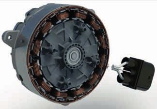
volts and higher will probably be introduced in       It will not, however, come about overnight. Fun-
                                   the near future. Many high-voltage auxiliary          damental questions relating to architectures
                                   components would need to be so heavily mod-           remain to be clarified. The systemic approach
                                   ified for these higher voltages that designers        has not yet been fully thought through and will
                                   would essentially be starting from scratch, driv-     continue to develop and evolve over the com-
                                   ing unit costs to even higher levels.                 ing years. What it is clear enough, however, is
                                                                                         that the 48-volt system will only enjoy a lasting
                                   While the prospect of on-board power systems          future if it is proves possible to standardise key
                                   with three different voltage levels might seem        components and to rapidly raise the number of
                                   economically infeasible at first sight, it could      units produced to significant levels.
                                   yet prove to be an opportune solution precisely
                                   for economic reasons: 48-volt auxiliary com-          1.5 VDA Recommendation 320
                                   ponents are significantly less costly than their      The VDA Recommendation 320 covers electric
                                   high-voltage equivalents. Power outputs of up         and electronic components in motor vehicles
                                   to five kW, and more in some cases, can be con-       for the development of a 48-volt power supply.
                                   trolled effectively with existing technology. Such    It was elaborated in the VDA’s Working Group
                                   components are typically produced in a fashion        “Electronics”, project group “48-Volt Power
                                   closer to the 12-volt or 24-volt versions than to     Supply”.
                                   high-voltage versions. That is also true for the
                                   costs associated with them. If high-voltage sys-      The document defines requirements, test condi-
                                   tems start to utilise very different voltage levels   tions and tests performed on electric, electronic
                                   in the medium term, sourcing BEV components           and mechatronic components and systems for
                                   from the 48-volt platform concept will become         use in motor vehicles with a 48-volt on-board
                                   an increasingly interesting proposition. Both         power supply. Unless otherwise indicated, the
                                   all-electric vehicles and 48-volt hybrids would       tests described in it are not electric service life
                                   stand to profit from such a development.              tests.

                                                                                         The voltages have been defined as follows
                                                                                         (figure 6: excerpt from VDA 320):

     Figure 6: Definitions of voltage ranges –                 Dynamic Overvoltage
     source: VDA 320, last updated July 2014
                                                                                                              60 V - U 48r,dyn
                                                                Static Overvoltage                            58 V - U 48r
                                                                                                              54 V - U 48max,high,limited
                                                                Limited Operation
                                                                                                              52 V - U 48max,unlimited
                                                                                                              48 V - U 48n
                                                           Unlimited Operation Range
                                                               Unlimited Operation

                                                                                                              36 V - U 48min,unlimited
                                                         Lower Limited Operation Range
                                                                Limited Operation
                                                                                                              24 V - U 48min,low,limited
                                                                  Undervoltage

                                                                                                              20 V - U 48stopprotect
                                                                Storage Protection
10
The range between U48r and U48r,dyn represents Requirements for components with 48
the tolerance. connection
• A single error must not cause a short circuit
Upper limited operation range between the 48 volt supply and the 12/24-
The range between U48max,unlimited and U48max- volt supply.
,high,limited
is intended for calibrating the storage • Components simultaneously supplied at 48
medium and for the uptake of recovered volt and 12/24 volt, and interfaces based on
energy. 12/24 volt, need their own ground connec-
tions for both supply voltages. These ground
Unlimited operation range connections must be physically separated
The range between U48min,unlimited and U48max,unlim- from one another.
ited
allows the components to operate without • If a 48-volt component loses its ground (ter-
restriction. minal 31 and/or terminal 41), this must not
disrupt or destroy communication networks
Upper limited operation range or the electrical networks.
The system may operate only temporarily in • Overcurrent tests should be detailed in the
the range from U48min,low,limited to U48min,unlimited. component specifications.
Countermeasures should be taken to bring • No component may cause the voltage to
about a return to the unlimited operation enter the dynamic overvoltage range (e. g.
voltage range. through a load dump or resonance peaks).
• If the voltage enters the overvoltage range
Undervoltage up to U48r, countermeasures should be taken
All voltages below U48min,low,limited are defined as via the component that is feeding energy
undervoltages. The storage protection voltage back in/causing entry into the overvoltage
is U48stoprotect. range, so that the voltage exits the overvolt-
age range at the lower boundary.
Storage protection voltage • If the voltage enters the lower limited
All voltages below U48stoprotect. function range, countermeasures should
be taken so that the voltage returns to the
General requirements unlimited operation range.
Assumptions regarding components with
48-volt connection 1.6 Additional technical challenges
• Static direct voltages ≤ 60 volt occur with a • Safety measures
maximum ripple of 10 percent RMS. From a technical point of view, the 48-volt
• A single error in the wiring harness must not voltage level meets key criteria defined in the
cause the 48-volt supply to short circuit to course of the discussion on 42-volt standard-
the 12/24-volt system. isation around the turn of the millennium. As
• There is a common ground for the 12/24- was already, and wisely, concluded back then,
volt system and the 48-volt system, which staying under the maximum permissible con-
are connected via physically separate tact voltage (< 60 volt) averts the need for
grounding bolts/connections. extensive personal safety measures such as
• All the voltage and current information contact protection, equipotential equalisa-
refers to the component (terminal voltage). tion and insulation control. The “hot plug-
• The polarity of the 48-volt supply is ging” effect must, nevertheless, be given due
prevented from reversing by appropriate consideration even at 48 volt, since opening
measures in the vehicle. an electric circuit under load can be enough
• Jump starting with the 48-volt power supply to destroy plug-in contacts. Safety measures
is prevented by appropriate measures here can either make it impossible to inter-
applied in the vehicle. rupt circuits under load, or ensure that their
disconnection is detected early enough for
the circuits to be deenergised in good time.
11EMC is also, given the high switched currents, As the number of 48-volt loads is still man-
a significant factor that deserves consid- ageable, load circuits are connected directly
eration. For these reasons, 48-volt electric to the power electronics and monitored there.
circuits are occasionally implemented with As the number of 48-volt high-power loads
shielded cables. In comparison to high-volt- rises, it will become necessary to use electric
age systems, the 48-volt voltage level does power distributors to monitor current paths
not present any risk of personal injury. Costly electronically (in addition to the deployment
personal safety measures are therefore not of safety fuses) so that even creeping short
required. circuits can be detected and switched off in
the event of a fault. Over and above this, it
• 48-volt electricity and power distribution must be ensured that the separation of both
In addition to the obvious difference in volt- the 48-volt and 12-volt systems is main-
age levels, several further technically signif- tained. A 48/12-volt short circuit would cause
icant differences between the 48-volt supply considerable damage to all 12-volt control
voltage and the 12-volt voltage level can be units and loads.
noted.
While breaking an electric circuit under load VDA recommendation 320 specifies that the
in a 12-volt system causes very little arcing, respective power distribution systems should
breaking loaded circuits at 48 volt can trigger be spatially separated. Each should have its
electric arcing that could lead to extensive own routing, and the wiring harnesses should
thermal damage at contact points. Creeping have separate grounding points. All 48-volt
short circuits, in particular, inevitably release components should be clearly distinguisha-
considerable amounts of electric arc energy ble by their colour from other components to
and cannot be de-energised using conven- ensure they are recognised as such.
tional safety fuses.
As such, safety fuses used today are by them- • Electric arcs1
selves not adequate to ensure that all sources As already mentioned, the introduction of
of faults in 48-volt systems are detected and voltage levels higher than 12 volts is accom-
safely switched off. It follows from this that panied by a risk of electric arcs forming if
electric circuits must, in addition to safety loaded circuits in the on-board power sys-
fuses, also be equipped with electronic sens- tem are interrupted. This could happen as a
ing to detect creeping short circuits and the result of the intentional isolation of electrical
formation of electric arcs and switch off the contacts in relays, but it could equally be the
relevant circuits in the event of a fault. result of a fault in a wire or connector..
1 Tschierse, Dietmar: „Translates as require-
ments for relays in the new dual-voltage
system“.
In: Elektronik Praxis 20, 20 Oct.2014.
Automotive Electronics // Bordnetz pp. 50-53.
Vogel Business Media GmbH & Co. KG,
Würzburg.
URL: http://www.elektronikpraxis.vogel.de/
automotive/articles/463717/
[Stand: 24/11/2014]
12This (figure 7) is what takes place when arc- • A metal vapour arc/anode arc/cath-
ing occurs: ode arc then forms (the temperature
• As the two contact surfaces separate required for an arc to ignite depends on
from each other when a connector is the specific materials, but if the burning
unmated, the reduced contact force voltage of the material is reached, an
before they open at the breaking point arc will ignite).
leads to increased contact resistance in • A gas/plasma arc forms.
the contact zone. • If measures are not then taken to extin-
• Formation of a bridge of molten metal guish the arc – by further increasing the
(the contact points begin to open: the distance between the contacts or using
increase in the strength of the electric arc chambers with magnets – very high
field causes material to begin to melt.) temperatures in the arc could lead to
• As the gap between the contacts gets thermal damage in its surroundings.
larger, the temperature of the bridge
rises until the melting voltage of the
contact material is reached.
As soon as the arc has ignited, the cath-
ode drop and anode drop voltage is pres-
ent at the opening contacts. The arc volt-
age increases linearly with the distance
between the electrodes until the arc is
driven into the quenching chamber and
the arc voltage rises sharply. The current
is limited by the switch arc and forced to
zero. The electric arc is quenched and the
normal on-board voltage is present at the
contacts.
Figure 7: Potential curve of an electric arc between two electrodes –
source: TE Connectivity
Using relays to switch loads under 12 volt and • Load limit curve
24 volt is a known and safe practice in passen- The switching capacity of a relay is normally
ger and commercial vehicles. In 48-volt appli- estimated using what is generally termed the
cations, new challenges present themselves. In load limit curve 2. This gives the load current
principle, steadily burning DC arcs can form – load voltage pairs in which safe shutdown
when switching conventional 12-volt relays. can be realised for Ohmic loads.
This mainly depends on the contact spacing. If
the distance between contacts is too small, the Figure 8 shows the load limit curve of a
electric circuit might not be interrupted when switching relay K (with single contacts) and
the contacts open, and the continuously burn- of a switching relay K-B (bridge contact) for
ing arc could destroy the relay. resistive loads. Values below the respective
load limit curve indicate that arcs are sure
to extinguish within, at most, ten ms. Values
13above the load limit curve indicate that a sta- If a single interruption with a given contact
ble arc forms – one which does not extinguish spacing does not suffice to switch off a cir-
even when the contacts are fully open. cuit, various options for the design of the
switching contacts are available to increase
the arc voltage:
• Greater spacing between contacts
• Multiple interruption (e. g. by utilising a
bridge contact that divides the arc into
several partial arcs in series)
• Lengthening the arc column using a
special electrode shape (e. g. classic
horn shape) with/without additional iso-
lation ribs
• Arc extinguishing plates: Separation of
the arc into several partial arcs (addition
of voltage drops of several drop areas:
Deion principle). Here, the arc is driven
into the arc extinguishing plates of an
appropriate plate chamber and divided
into partial arcs, resulting in a substan-
tially increased total voltage drop.
• Cooling the arc using cooling or insulat-
Figure 8: Load limit curve for the switching relay K-B and the switching relay K – ing material chambers.
source: TE Connectivity
142. Architectures
2.1 Powertrain Figure 9 illustrates a topology where the inter-
Several powertrain topologies are feasible due nal combustion engine (ICE) and e-machine
to the various options to mechanically connect cannot be separated. Consequently, IC engine
and integrate the 48-volt electrical machine friction takes place in recuperation and electri-
(usually as a starter generator in 48-volt tech- cal driving mode, reducing the performance of
nology) into the drivetrain, and the different the IC engine. In contrast, the topologies in fig-
types of 48-volt electrical machines available ures 11 and 12 show an IC engine that can be
for selection. The powertrain topology chosen decoupled. This increases the potential amount
significantly influences the performance and of recuperable electrical energy and reduces
characteristics with which the aforementioned the electrical power required for the desired
functions can be implemented, as well as the driving function.
costs involved. Carmakers and automotive sup-
pliers are currently analysing and evaluating This is in principle also possible with the topol-
four major powertrain topologies. Depending ogy shown in figure 10, provided that addi-
on the e-machine configuration, the topologies tional coupling is implemented between the IC
vary in terms of their potential for energy recu- engine and the 48-volt electrical machine (P2
peration and electrical boost capacity. hybrid).
ICE mounted (e.g. belt) – mHEV
Engine MT
48V e-Drive
Figure 9: Belt-driven 48-volt electrical machine – source: Robert Bosch
Crankshaftmounted (ISG) – mHEV
48V e-Drive
Engine
Automated
Transmission
Figure 10: Crankshaft-mounted 48-volt electrical machine – source: Robert Bosch
15The introduction dates and prioritisation of the The easiest mode of integrating the electrical
individual topologies differ between the vari- machine and the most extensively analysed
ous manufacturers, and depend on the efforts topology to date is illustrated in figure 9.
required to achieve defined CO2 target values,
on regional requirements and on the scope of
features offered to the end customer.
Transmission mounted (eDCT) – sHEV
48V e-Drive
Engine
Double Clutch
Transmission
Figure 11: Dual-clutch transmission-mounted 48-volt electrical machine – source: Robert Bosch
Transmission mounted (eMT/eAMT) – sHEV
Engine
MT/AMT
48V e-Drive
Figure 12: 48-volt electrical machine mounted to the transmission output shaft – source: Robert Bosch
162.2 Types of electrical system topologies
The maximum and continuous current deter-
mine the configuration of the electrical system.
12-volt electrical systems will be equipped with
lead-acid batteries for the foreseeable future
due to their ability to start the engine even at
very low temperatures. In addition, this low-cost
solution has been tried and tested for many
decades.
Figure 14: 12-volt full load – source: Leopold Kostal
The current limit is to be set to 250 A contin-
uous current for both systems. However, short
peak currents may be significantly higher. • 12-volt systems with higher voltage loads
Higher continuous currents require larger cable Higher voltages are already used in vehicles
cross-sections, which adds bulk and drives up to supply headlights and windshield defrost-
costs. Since the 48-volt system primarily sup- ers. These power-consuming devices produce
plies high-power components, it is currently the required voltage themselves locally (fig-
switched off in most applications when the ure 15).
vehicle is not moving.
• Traditional 12-volt electrical systems
In traditional 12-volt systems, the maximum
current flows when the IC engine is started.
This current must be fully supplied by the
12-volt lead battery. When the engine is
running, the generator feeds the electrical
system with currents of up to 350 amperes.
The system voltage is then 14 volts (figure
13 and 14).
Figure 15: 12-volt electrical system with higher voltage devices –
source: Leopold Kostal
• 12-volt electrical systems with 48-volt
stand-alone solutions
In systems with short-term high power
requirements, e. g. for roll stabilisation or
electric turbochargers, a DC/DC converter
is used to increase the voltage from 12 to
48 volts. The higher voltage level features
an energy storage medium that covers the
energy peaks and reduces the load on the
generator of the 12-volt system and on the
DC/DC converter. Compared to a 12-volt
Figure 13: 12-volt start process – source: Leopold Kostal electrical system, the system components
and wiring of this application have smaller
dimensions. The DC/DC converter can be uni-
directional.
17Capacitors can also be used to store electric when the IC engine is running. The DC/DC
power in addition to batteries. The 12-volt converter transfers part of this energy to the
lead-acid battery still supplies the power to 12-volt system to supply its components and
start the engine (figure 16). charge the lead battery (figure 17).
The topology of this system features high-
power components in the 48-volt system; the
power transfer to the 12-volt system could be
as low as just one kW. However, at extremely
low temperatures, the lithium-ion batteries
can no longer supply sufficient energy to
start the engine. In this case, the 12-volt lead
battery comes into play, powering a tradi-
tional starter in the 12-volt system or using
a bidirectional DC/DC converter to power the
Figure 16: 12-volt electrical system with generator and 48-volt electrical system without generator – source: Leopold Kostal belt-driven starter generator (BSG) in the
48-volt system (figure 18).
• 12-volt system combined with a 48-volt
system It can be assumed that mild hybrids will oper-
The power to start the IC engine is usually ate without a starter in the 12-volt system
supplied by the lithium-ion battery in the after a transition phase, and that the latter-
48-volt electrical system. The starter gen- most system topology described will become
erator is a closed-loop controlled electrical established.
machine using electronic devices to limit
power consumption. According to the current
state of technology, the starter generator can
feed up to 15 kW into the 48-volt system
Bild 17: Start of an IC engine with 12-volt starter, when the lithium-ion battery is too cold – source: Leopold Kostal
Figure 18: Start of an IC engine with 48-volt starter and transfer of power from 12-volt system via DC/DC converter, when the lithium-ion
battery is too cold – source: Leopold Kostal
183. Components
3.1 Generators and motors While 12-volt generators are claw-pole
It is envisioned that 48-volt systems of all types machines due to their system design, the intro-
will operate without the traditional 12-volt gen- duction of 48-volt systems will lead to the coex-
erator, since the 48-volt machine takes over the istence of different technologies. Two machine
generator function. Thanks to the higher volt- technologies exist – synchronous and asynchro-
age, the machine’s performance and efficiency nous machines (figure 19).
will improve.
Synchronous machines are subdivided into
In contrast to 12-volt generators, electric machines with exciter winding, either of the
machines fulfil two different functions. They salient-pole or claw-pole rotor type, perma-
operate both as generators and starters or nent magnet synchronous machines and reluc-
rather electrical motors to support propulsion. tance machines. Asynchronous or inductance
Consequently, situations requiring torque and machines are also known as squirrel-cage
high electrical power at the same time are a machines due to their rotor technology. The
challenge for the energy management of the cage can be made of aluminium or copper.
electrical system. Key parameters include the
total system load, the charging status (SOC and The speed, efficiency and power density of the
SOH) and the dimensioning of the batteries. machines may vary subject to the power and
The energy management system controls the maximum current of their respective rectifi-
activation of individual functions, such as the ers. It is therefore difficult to classify any sin-
charge, boost or recuperation modes, in the gle machine as per se the best type, e more
context of the specific driving situation. so since the automotive industry also requires
additional factors such as package space, costs,
robustness and standardisation to be consid-
ered. This explains why different technologies
will be come to be used in 48-volt motor gen-
erators.
Synchronous machines Asynchronous machines
(inductance machines)
Machines with Permanent magnet Reluctance
exciter winding machines machines
Salient- Claw-pole Rotor with rare Rotor with Copper rotor Aluminium rotor
pole rotor rotor earth magnets ferrite magnets
Figure 19: Classification of electric machines – source: Valeo
19As a result of the multiple topologies and
machine types available, no single “stand-
ard architecture” or “standard machine type”
will dominate. In fact, the introduction of the
48-volt system will lead to variabilisation as a
result of different factors such as the required
torque, existing platforms, costs, package
space, robustness and CO2 targets.
Figure 20: Belt-driven e-machine – source: Valeo
3.2 Heaters and additional heating sys-
However, the topology of the powertrain signifi- tems
cantly influences the machine technology: • Electrical heaters
• In the future, 48-volt e-machines with belt It is advisable to integrate the electrical
drive (figure 20 and figure 9, section 2.1) heater, a high power-consuming device in
will replace traditional 12-volt generators. 12-volt systems, into the 48-volt electrical
It is likely that inductance machines will be system, where it can access a power range
used in addition to the claw-pole technology between three and five kW.
known from standard 12-volt architectures.
Inductance technology is already employed
in series production of belt-driven machines.
The inverter electronics are usually integrated
into the machine. The machine or electronics
can be either air or water-cooled subject to
requirements.
• Crankshaft-mounted motors/generators, also
known as ISG (figure 10, 2.1.), are usually flat
machines that must meet high requirements
in terms of package space and ease of inte-
gration regarding their diameter (determined
by the IC engine or gear) and length. This is Figure 21: Transmission-mounted e-machine – source: Valeo
why machines with the maximum possible
power density are preferably used, which in • Air heaters
turn makes permanent magnet machines an Air heaters are usually used in 12-volt sys-
obvious choice. tems. This type of heater directly heats the
air that is directed to the passenger compart-
• Transmission-mounted machines (figure 21 ment and is thus integrated into the air-con-
and figure 12, section 2.1) are, whether inte- ditioning system. It quickly heats up the vehi-
grated into manual or dual-clutch transmis- cle interior and defrosts the windshield with
sions, cylindrical in shape, like belt-driven minimum heat transfer loss.
machines. Since they are cooled with trans-
mission oil, these machines must be brush-
less. The use of permanent magnet or induct-
ance machines instead of claw-pole machines
is under consideration for this reason. The
torque that can be supplied in the specified
package space is key to the decision since it is
higher in permanent magnet machines than
in inductance machines.
20Having already become accepted in 12-volt The air-conditioning system uses the air-to-wa-
systems, this heater technology will most ter heat exchanger of the cooling circuit to heat
likely be the first to be used in 48-volt sys- the vehicle interior and defrost the windshield.
tems due to its easy transferability. Other Compared to an air heater, the heat transfer
heating technologies (wire heaters, layer loss is higher since the heat is transferred twice.
heaters) are also conceivable. Which tech- However, by heating the coolant, the IC engine
nology will prevail still remains to be seen, can be brought quickly to its operating temper-
since it will depend on multiple factors such ature and the temperature of the 48-volt bat-
as costs and the electrical behaviour of the tery can be controlled with the heating system.
heaters in the on-board power system. If nec-
essary, an additional heater will be used to
heat the lithium-ion battery.
• Water heaters
The water heater is tied into the hydraulics of
the engine coolant system (figure 22).
Figure 22: Electric water heater – source: Webasto
3.3 Air-conditioning compressors The change to 48-volt supply voltage leads
Operating an electric compressor independently to significantly higher electric currents with
of the engine makes it possible to improve the peaks of around 240 amperes. The winding
energy efficiency of the air-conditioning system of the electric motor and the dimensioning of
as part of an overall energy management strat- the inverter must be adjusted to the electrical
egy, and provides additional thermal comfort conditions. High currents and current densities
in summer by pre-cooling the car. Belt-driven lead to higher power losses in electronic com-
compressors ranging from three to six kW are ponents and hence to higher waste heat flows.
currently dominating the market. This must be taken into consideration when
dimensioning the cooling management of elec-
Electric compressors are nowadays used in tronic components.
almost all electric vehicles and in many types of
hybrid vehicles (figure 23). The inverter, elec-
tric motor and mechanics form a single unit.
The necessary power is provided by the existing
high-voltage system with controllable electric
amperages. Modern electric compressors can
take voltages between approx. 120 and 450
volts. Their protective features eliminate the
risk of contact and isolate the high-voltage sys-
tem from the low-voltage system.
21Figure 23: Electric compressor – source: Mahle Behr Figure 24: Electric coolant pump – source: Brose
The use of 48-volt compressors is technically Transmission fluid and engine oil pumps (fig-
feasible but requires substantial changes to ure 25) can fully replace today’s mechanical
the electric system. Space requirements, weight main pumps and electric auxiliary oil pumps,
and costs all increase as a result. The defined while optimising the costs and efficiency of
package space must be adjusted to the dimen- automatic transmissions and maintaining
sions of 48-volt compressors. the oil pressure after the IC engine has been
switched off.
3.4 Pumps
The 48-volt system promotes the use of power-
ful electrically-operated auxiliary components.
These include various pumps (for oil, coolant,
air, fuels). They can be activated on demand
and controlled, thus reducing energy consump-
tion and emissions while also minimising wear
and tear. The maximum output increases from
currently around one kW to six kW. A clear
market trend towards higher power outputs in
combination with better control and analysis
options can currently be identified.
Electric coolant pumps contribute to the imple- Figure 25: Electric oil pump – source: Brose
mentation of beltless IC engines (figure 24).
3.5 Windshield defrosters
Electric windshield defrosters have been in use
for many years. They often use thin heating
wires embedded in the glass. Another increas-
ingly used variant are layer-heated windshields.
The windshield is heated by a transparent, elec-
trically conductive coating, usually applied to
one of the glass surfaces. The heating structure
is no longer visible to the driver.
22As a result of increasingly larger glass surfaces In modern vehicles, window heaters primarily
and higher requirements for the melting speed, perform a comfort function when the engine is
power peaks of more than one kW occur in started. It usually takes only a few minutes to
these systems. Power densities of 1,000 W/m2 thaw frost from the windows. The heating is also
are usually necessary to achieve subjectively used to prevent or clear condensation.
quick defrosting (figure 26).
Figure 26: Thermal image of an electrically heated windshield – source: NSG
It is therefore safe to assume that window heat- Direct electric heating of the window is more
ers will become more important, especially in efficient and can be controlled better than
future electric vehicles without IC engines where indirect heating with hot air. In this context,
they are likely to be deployed more often. Care- extension of electric heating to other car win-
ful energy consumption is essential in these dows also appears desirable. Complete heat-
vehicles since the use of HVAC can sometimes ing of all windows would require a connected
reduce the driving range of an electric car quite load of up to 2.5 kW for a total surface area of
significantly. 2-3 m2. 48-volt systems can help provide the
high power required for window heating, which
However, lower energy usage for cabin heating may sometimes be drawn for extended periods
and air-conditioning will considerably increase of time, as an integral component of the car’s
the risk of fogging and condensation on all air-conditioning system.
windows. In addition to defrosting the windows
when starting the car, window heaters will most
likely also be used in continuous operation to
prevent fogging and condensation while the
vehicle is moving.
233.6 Chassis functions In this respect, EPS does not require a 48-volt
The power consumption of electrically pow- supply. The question as to whether the ben-
ered chassis systems with peaks in the kilowatt efits of EPS using a 48-volt motor may jus-
range is high for the on-board power systems tify conversion still needs clarification. Con-
of passenger cars. Examples are electric power sequently, EPS is not a driving force behind
steering (EPS), rear steering, roll stabilisation the introduction of 48-volt electrical systems.
and active suspension/damping. As a result of However, it is rather likely that the possibility
the power requirements, chassis systems are of 48-volt EPS will be investigated as soon
automatically candidates for a 48-volt supply, as such 48-volt systems have been realised.
which is even already demanded by some chas- The 48-volt solution can offer particular ben-
sis systems. efits for vehicles equipped with EPS and rear
steering. The steering systems on the front
Electric power steering and roll stabilisation are and rear axle are controlled simultaneously
described in more detail below. and thus require higher peak power from the
electrical system. The use of a 48-volt system
• Electric power steering (EPS) could significantly reduce the loads, which
Until the end of the nineties, the notion pre- the 12-volt system has to supply.
vailed that EPS could only handle front axle
loads in small to mid-size cars. The energy • Roll stabilisation
provided by the 12-volt motor was insuf- In 2014, a major carmaker presented an
ficient to ensure adequate power steering electric roll stabilisation system running on
support. Executive and luxury cars were fitted 48 volts (figure 27).
with hydraulic power steering. Technologi-
cal developments in electric power steering The concept features a standard 12-volt
enabled increasingly higher axle loads. EPS on-board power system and a DC/DC con-
running on 12 volts can nowadays be used verter that generates 48 V for the exclusive
in almost all passenger cars and is likely to supply of the electric roll stabilisation system.
replace hydraulic power steering. Consequently, it is not a 48-volt on-board
power system but rather a 48-volt stand-
alone solution. This stand-alone solution
can be considered as the first step towards
48-volt electrical systems.
• Advantages of electromechanical chassis
systems
Electromechanical chassis systems only need
power from the electrical system for actuat-
ing components, and they provide significant
benefits in efficiency compared to hydrau-
lic systems. In addition, electric motors can
provide much faster actuation than systems
using hydraulic fluid. As a result of these
benefits in efficiency and dynamics, carmak-
ers favour the electrification of chassis com-
Figure 27: 48-volt supply for electric roll stabilisation – source: Porsche ponents.
• Effects on the electrical system
Ride control (e. g. compensation of uneven
road surfaces) and highly dynamic driving
manoeuvres place high demands on chassis
24dynamics that are reflected in power peaks The following two examples show cooling fan
in the electrical system. 12-volt electrical drives (figures 28 and 29) in different scalable
systems cannot meet these dynamic power power classes for a wide range of dimensioning
requirements and quickly reach the limits variants.
of their performance capability. In addition,
the current required to flow in a 12-volt sys-
tem would result in high power losses in the
energy distribution. The more chassis com-
ponents are electrified in vehicles, the more
frequently power peaks will occur in electrical
systems. This can be addressed through the
introduction of a higher voltage level, under-
lining the necessity of 48-volt systems.
• Package space
In terms of package space, 48-volt systems
provide no benefits for chassis actuators.
While 12-volt actuators have a lower num- Figure 28: Cooling fan drive for low performance classes (up to
600 W output power) – source: Brose
ber of turns than 48-volt actuators, their
wire cross-section is higher. If winding space
and power requirements remain unchanged,
48-volt actuators will provide no significant
package space benefits compared to 12-volt
systems.
The advantages of 48-volt technology are par-
ticularly evident in dynamic handling char-
acteristics, in the packaging and assembly
technology of electronic components and in
the performance requirements of electrome-
chanical chassis systems. In addition, the intro-
duction of a higher voltage level considerably
reduces power losses in supply lines. A higher
voltage level is also imperative for optimal per-
formance of chassis components during energy Figure 29: Cooling fan drive for high performance classes (up to
1,000 W output power) – source: Brose
demand peaks. The 48-volt platform will enable
comprehensive electrification of chassis com-
ponents and distinctively improve the dynamic The advantages of a high supply voltage are
properties of vehicles. particularly evident in the higher performance
classes. Smaller cable cross-sections, less stress
3.7 Fan motors on connectors and reduced current loads on the
Loads with high power throughput are gener- necessary semiconductors and passive system
ally more likely to be implemented in 48-volt filter elements are all benefits that outweigh
systems. Given the issues presented by power the disadvantage of the necessary higher die-
losses in supply lines and in the magnetic cir- lectric strength. Depending on the application,
cuit, and given the high thermal requirements the difference between the supply voltage and
applicable to the integration of their power the internal useful voltage of logic devices may
units, high-performance fans used for purposes require more Changes to the circuitry to be
such as engine cooling particularly benefit from made. The 12-volt and 48-volt systems have
the higher efficiency levels which are possible been appropriately separated. Special attention
in 48-volt systems. was given to creepage distance and clearance.
25The ground connection of the drives is designed Traditional automotive connectors used in
as a star grounding system and ensures low-in- 48-volt systems, must always be checked
terference operation thanks to capacitive cou- for compliance with creepage distance and
pling to ground. clearance requirements according to DIN EN
60664-1 (insulation coordination for equip-
3.8 Connecting systems ment within low-voltage systems) and evidence
The question as to which electrical connection of compliance must be demonstrated.
system should be used for 48-volt systems can
be answered by looking at the technical chal- For determining the creepage distance and
lenges arising from the increased system volt- clearance, the connectors must meet the
age. Connector systems that have been tried requirements for pollution degree 2 and an
and tested in cars (14 volt) or heavy goods altitude of 5,500 m asl. Most of the watertight
vehicles (28 volt) for many years represent a connector systems fulfil these requirements,
cost-neutral solution for 48-volt systems. since they observe the necessary clearances
between the contact pairs. By contrast, connec-
Adopting the high-voltage connectors (which tor systems that are not watertight, and espe-
are typically shielded and have built-in con- cially miniaturised systems, do not fulfil these
tact protection) that have been developed for specifications or only meet them partially. The
use in electric and hybrid vehicles up to 850 housing design plays a key role in this con-
volts would be technically feasible, but cost and text. To ensure that housings meet creepage
package space considerations make it seem distance and clearance requirements, a design
inadvisable. where contacts are inserted only in every sec-
ond chamber could be deployed.
However, the technical challenges arising from
the introduction of 48-volt systems should not
be entirely disregarded, e. g. pulling a connec-
tor under load and the electrolytic processes
following the ingress of electrolyte-contain-
ing moisture in energised connectors. The use
of watertight connectors is therefore recom-
mended. It would also be advantageous to sep-
arate and individually seal the contact cham-
bers (figure 31). A systemic architecture should
be selected for disconnecting a connector under
load to ensure that any interrupted contact is
detected and the relevant path is de-energised.
Figure 30: Size difference between 48 volts (green) and
high-voltage (orange) – both configured for 2.5 mm2 – source: TE
Connectivity
26With regard to the system architecture, cost sav-
ings result from the following reduced require-
ments:
• no contact protection required in connectors
• no special dielectric strength (creepage
distance and clearance) required
• no shielded cables required
• no HVIL pilot line (to prevent disconnection
under load) required
• no isolated grounding (B-) requiredh
In 48-volt systems, the following cost drivers
Figure 31: 2-pin connector with individually sealed chambers for
48-volt applications – source: TE Connectivity are likely to be avoided:
• high-quality contact systems with low contact
3.9 Wiring harnesses resistance
Since modern 12-volt wiring harnesses and • wiring harnesses with separate routing paths
their components are specified for voltages up and costly cable protection
to 60 volts, the unrestricted use of all compo- • sealed systems (anti-corrosion protection)
nents would be theoretically possible in 48-volt • modification of connecting systems
systems. It is nevertheless necessary to analyse
the systemic effects that result from the com- However, reducing the requirements mentioned
bined use of two different voltage levels in one above (e. g. HVIL) will affect the safe use of
environment. The main challenge will be the components. For instance, disconnecting a con-
provision of fuse protection isolating the two nector under load should also be avoided in
systems from one another. If both systems relia- 48-volt systems. The 48-volt electrical system
bly detect short circuits, a short circuit involving may turn out to be as complex and cost-inten-
both voltage circuits can lead to significant dis- sive as the high-voltage system due to safety
turbances. Therefore, it is essential to introduce and EMC considerations, and will perhaps be
an intelligent control mechanism and/or to spa- even more expensive in the first few projects
tially separate both voltage levels reliably. as a result of the initial outlay required. More-
over, abandoning safety measures installed
Compared to high-voltage systems, the 48-volt in high-voltage systems will make additional
system meets the demand to provide more elec- protection features such as the frequently dis-
trical power at a lower cost. Virtually all vehicles cussed arcing detection necessary.
in the mid-size to luxury segment feature start-
stop systems and have high power require-
ments. In these car segments it is likely that a
48-volt system (in addition to a 12-volt system)
could prove viable for all non-high voltage
vehicles.
However, the 48-volt system cannot fulfil the
requirements for all-electric cars or full hybrids.
The 48-volt system is not an alternative but an
addition to high-voltage technology, one that
will be more viable and sustainable the lower
the costs are.
27You can also read