Big Bubba Model BB-S100 - Installation, Operation, and Maintenance Manual - Watts
←
→
Page content transcription
If your browser does not render page correctly, please read the page content below
IOM-WQ-BB-S100
Installation, Operation, and Maintenance Manual
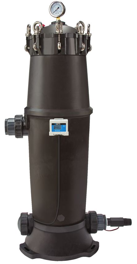
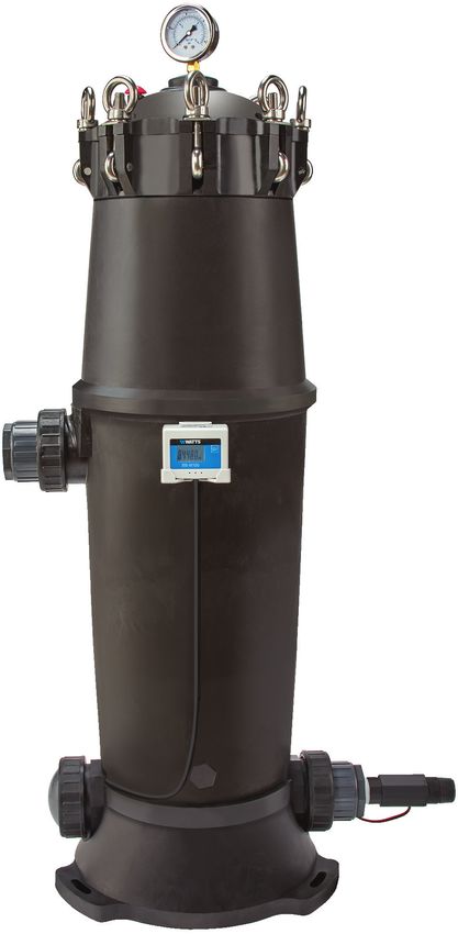
Big Bubba® Model BB-S100
A Complete Whole Home System Solution for
the Reduction of Lead, PFOA/PFOS, Cysts, and Chlorine Taste & Odor
Certified by IAPMO R&T to NSF/ANSI 42 and 53, for the reduction
of claims verified and substantiated by test data as specified on
the performance data sheet. The system is also certified to CSA
C ®
B483.1, and NSF/ANSI 372 for Lead Free compliance.
Congratulations on your purchase of the Watts BB-S100 complete whole home system solution!
You have made a great choice to protect your home against Lead, PFOA/PFOS, Cysts, and Chlorine
Taste & Odor. This system is effective against a multitude of contaminants and is loaded with features
including a single high capacity replaceable filter cartridge rated for 84,480 gallons and a volumetric
flow monitoring system with filter cartridge change alert. The BB-S100 system uses the robust Watts
Big Bubba® filter housing, a trusted icon of the water filtration industry, so you can trust your system
will be durable and simple to maintain.
Thank You!
  The Watts Team

Lead and PFOA/PFOS contamination of drinking water is a major concern for many consumers due
to the health issues they may cause. According to the USEPA, lead can cause behavior, learning,
and low IQ problems in children as well as kidney and cardiovascular issues in adults. While the risks
associated with PFAS chemicals are still largely unknown, the USEPA says studies indicate exposure
to PFOS and PFOA (the most extensively produced and studied of these chemicals) can cause
reproductive and developmental, liver and kidney, and immunological effects, as well as tumors, in
laboratory animals.

2    IOM-WQ-BB-S100 2130                            EDP# 68110146                             © 2021 Watts
Introduction
  ! WARNING
               Read this Manual BEFORE using this equipment.
               Failure to read and follow all safety and use information
               can result in death, serious personal injury, property
               damage, or damage to the equipment.
               Keep this Manual for future reference.

If you are unsure about installing your Watts Filter system contact          Table of Contents
a Watts representative or consult a professional plumber.
                                                                             Overview  . . . . . . . . . . . . . . . . . . . . . . . . . . . . . . . . . . . . . . . . . 4
You are required to thoroughly read all installation instructions
and product safety information before beginning the installa-                Equipment Specifications . . . . . . . . . . . . . . . . . . . . . . . . . . . . . 4
tion of this product. FAILURE TO COMPLY WITH PROPER                          Operational Parameters and Feed Water Guidelines . . . . . . . . . 4
INSTALLATION AND MAINTENANCE INSTRUCTIONS                                    Dimensions-Weights . . . . . . . . . . . . . . . . . . . . . . . . . . . . . . . . . 5
COULD RESULT IN PRODUCT FAILURE WHICH CAN                                    Flow Rate and Pressure Drop . . . . . . . . . . . . . . . . . . . . . . . . . . 6
CAUSE PROPERTY DAMAGE, PERSONAL INJURY AND/
                                                                             Installation Precautions . . . . . . . . . . . . . . . . . . . . . . . . . . . . . . . 7
OR DEATH. Watts is not responsible for damages resulting
from improper installation and/or maintenance. Local building or             Contents of Filter System . . . . . . . . . . . . . . . . . . . . . . . . . . . . . 7
plumbing codes may require modifications to the information pro-             System Diagram . . . . . . . . . . . . . . . . . . . . . . . . . . . . . . . . . . . . 7
vided. You are required to consult the local building and plumbing           Preparing the System for Installation . . . . . . . . . . . . . . . . . . . . 8
codes prior to installation. If this information is not consistent with      Installation  . . . . . . . . . . . . . . . . . . . . . . . . . . . . . . . . . . . . . . . . 9
local building or plumbing codes, the local codes should be fol-
lowed. Save manual for future reference.                                     System Start Up Procedure . . . . . . . . . . . . . . . . . . . . . . . . . . 11
Refer to the enclosed for operating parameters to ensure proper              Volumetric Flow Monitor Operation . . . . . . . . . . . . . . . . . . . . . 11
use with your water supply.                                                  Installation Diagrams  . . . . . . . . . . . . . . . . . . . . . . . . . . . . . . . 12
                                                                             Filter Cartridge Replacement Procedure . . . . . . . . . . . . . . . . . 13
If this equipment, or any of its parts, becomes damaged                      Replacement Parts . . . . . . . . . . . . . . . . . . . . . . . . . . . . . . . . . 14
or needs repair, stop using the equipment and contact an                     Troubleshooting  . . . . . . . . . . . . . . . . . . . . . . . . . . . . . . . . . . . 16
experienced service individual immediately.                                  Performance Data Sheet  . . . . . . . . . . . . . . . . . . . . . . . . . . . . 17
• Use only lead-free solder and flux for sweat-solder connec-               Volumetric Flow Monitor Quick Reference Guide  . . . . . . . . . . 18
   tions, as required by state, province and federal codes.                  Limited Warranty  . . . . . . . . . . . . . . . . . . . . . . . . . . . . . . . . . . 20
• Handle all components of the system with care. Do not drop,
   drag or turn components upside down.
• Be sure the floor under the system is clean, level and strong
   enough to support the system while in operation.
• Install the system in a protected area.
• Do not attempt to treat water over 125°F (51°C) with the sys-
   tem.
• Always connect the system to the main water supply pipe
   before the water heater.
• Do not expose the system to freezing temperatures. Water
   freezing in the system causes equipment damage.
• Do not install in direct sunlight. Ultraviolet rays from the sun
   may cause damage.
• A 5 micron disposable cartridge filter may be required as a
   prefilter to this system to prevent premature clogging of the
   BB-S100 system filter cartridge by sediment.

  ! WARNING                                                                     ! CAUTION
 Do not use with water that is microbiologically unsafe or of unknown        Test the water periodically to verify that the system is per-
 quality without adequate disinfection before or after the system.           forming satisfactorily.
 System certified for cyst reduction may be used on disinfected
 waters that may contain filterable cysts.

IOM-WQ-BB-S100 2130                                                  EDP# 68110146                                                              © 2021 Watts                   3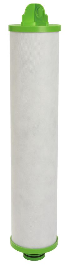
Overview                                                                  Operational Parameters and
Thank you for your purchase of this quality Water Treatment sys-
                                                                              Feed Water Guidelines
tem solution.
                                                                                NOTICE
Your new system is equipped with a high capacity carbon
block filter cartridge with Lead, PFOA/PFOS, Cysts, Sediment,              Installation must comply with state and local plumbing regula-
Chlorine and Chloramine reduction capability. Another great fea-           tions.
ture of this system is the volumetric flow monitor that alerts you
when the filter cartridge needs to be changed based on water               Please review operating pressures, temperatures and water
usage. The BB-S100 water filtration system provides clean,                 chemistry limitations to ensure compatibility.
clear, great tasting water to your entire home and has a 84,480
gallon filtration capacity for the reduction of Lead and PFOA/             pH . . . . . . . . . . . . . . . . . . . .  6.5 to 8.5
PFOS. The system is certified to reduce Lead (soluble and insol-           Min/Max Water Pressure . . . .  2
                                                                                                            5psi to 125psi /172 kPa to
uble), PFOA/PFOS, Cysts, and Chlorine.                                                                     861 kPa
This system is designed for point of entry installation for whole          Min/Max Water Temperature. .  3
                                                                                                          4 to 125°F / 1 to 52°C
home treatment and to be simple and convenient to service.                                               (125°F / 52°C at 80psi
                                                                                                         maximum pressure)
                                                                           Free Chlorine (maximum) . . . .  2.0 mg/L
    System Maintenance                                                     Iron (maximum). . . . . . . . . . . .  0.3 mg/L
                                                                           Manganese (maximum) . . . . .  0.05 mg/L
It is important to change the filter cartridge at the recommend-           Oil and H2S. . . . . . . . . . . . . .  None Allowed
ed interval indicated in this manual. Many contaminants are not
detectable by taste. In addition, other bad tastes and odors may           Turbidity/Sediment. . . . . . . . .  P
                                                                                                                 re-filter inlet water with 5 micron
become apparent over time if the filter cartridge is not replaced                                               sediment filter if sediment/turbid-
when needed.                                                                                                    ity prevents BB-S100 filter car-
                                                                                                                tridge from achieving full volume
Should you have any further questions, please call our customer
                                                                                                                capacity
service (978) 689-6066 or your Watts representative.
                                                                           System Electrical
                                                                           Requirements. . . . . . . . . . . . .  2 AA Alkaline Batteries

    Equipment Specifications                                               For all other guideline information please contact your Watts
                                                                           representative. Water that does not meet the above guidelines
                                                                           will require additional pre-treatment.
This Watts water filtration system is complete, and self-con-
tained, with the filter cartridge pre-installed in the filter housing.
Some light assembly is required to install plumbing adaptors,
volumetric flow monitor and inline flow meter. Please review oper-
ating pressures, temperatures and water chemistry limitations to
ensure compatibility and performance.

4       IOM-WQ-BB-S100 2130                                              EDP# 68110146                                                 © 2021 Watts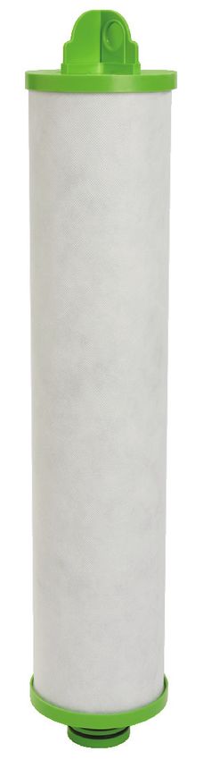
Equipment Specifications

Dimension — Weights
  MODEL NO.                                          DIMENSIONS                                           SHIPPING WEIGHTS     OPERATING WEIGHT
                      A                 B                 C*                 D                E
                in.       mm      in.       mm      in.        mm      in.       mm     in.       mm       lbs.      kgs        lbs.      kgs
   BB-S100     21.6       549     3.9       99     42.6        1082   14.2       361   22.3       566.4    64         29        123        56

*Allow 36" clearance above the top of the system for filter cartridge replacement.
All dimensions are +/- 1" and are subject to change without notice.

IOM-WQ-BB-S100 2130                                             EDP# 68110146                                              © 2021 Watts           5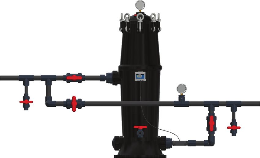
Equipment Specifications
SYSTEM MODEL NO. BB-S100
Minimum/Maximum Operating Temperature* 34 to 125°F / 1 to 52°C (125°F / 52°C at 80psi Maximum Pressure)
Minimum/Maximum Operating Pressure* 25psi to 125psi / 172 kPa to 861 kPa
Maximum Continuous Flow Rate for Lead & PFOA/PFOS Reduction** 4 GPM (15 lpm)
Maximum Flow Rate for Chlorine Reduction*** 13 GPM (49.2. lpm)
Maximum Flow Rate for Chloramine Reduction*** 7 GPM (26.4 lpm)
Inlet and Outlet Connection Size/Type 1" NPT
Unfiltered Water Housing Drain Port Connection Size/Type ½" FNPT
Filter Housing Body Material Glass Reinforced Polypropylene
Inlet Pressure Gauge Port 1⁄4" FNPT Brass Reinforced
Inlet Pressure Gauge Included Yes
Swing Bolts (Lid) Material 304 Stainless Steel
O-ring (Lid) Material EPDM
O-ring (Plumbing Adaptors) Material EPDM
Nominal Micron Rating 0.5 Micron Nominal
Filter Housing Anchor Kit Included Yes- 3/8" Concrete Anchors (X3)
Number of Filter Cartridges 1
Filter Cartridge Media Type Lead Adsorption Carbon Block
Filter Cartridge End Cap Material/Color Glass Reinforced Polypropylene/Green
Filter Cartridge Top Endcap Includes Handle Yes
Filter Cartridge O-ring (Dual) Material EPDM
Maximum Allowable Filter Cartridge Pressure Drop 40psi Drop
Flow Monitor Display Type 5 Digit LCD- Volumetric Count Down to “0”
Flow Monitor Capacity 84,480 Gallons (Resettable / Non Programmable)
Positive Indication of Flow Yes- Flow Wave Icon On Display
Flow Monitor Alarm at “0” Gallons Remaining During Water Flow: Visual- Flashing “0 gal” on Display/ Audible- Beeping Alarm
Flow Monitor Power Supply 2 AA Alkaline Batteries
Low Battery Alarm Yes- Visual Low Battery Icon and Audible Beeping Alarm
Flow Meter Type Inline Flow Through Turbine Meter
Flow Meter Connection Size/Type 1" x 1" MNPT
Flow Meter Body Material Glass Reinforced Polymer
*Minimum and Maximum Operating Temperatures and Pressures listed above apply to complete system as well as all individual components including
filter housing, filter cartridge and volumetric flow monitor/meter.
** See Certified Substance Reduction for specific flow and reduction claims.
***Claims are not performance tested or certified by IAPMO. Performance claims are based on independent laboratory and manufacturer’s internal test
data. Actual performance is dependent on influent water quality, flow rates, system design and application. Results may vary. See Certified Substance
Reduction for certified chlorine flow and reduction claims.
Flow Rate and Pressure Drop
Flow Rate and Pressure Drop
30 Low Pressure Drop
25
Pressure Drop (psi)
The Watts BB-S100 system uses
20
a large, high capacity carbon block
15
filter cartridge to ensure the highest
10
degree of performance while offer-
5
ing the highest possible flow rate at
0
1 2 3 4 5 6 7 8 9 10 11 12 the lowest possible pressure drop.
Flow Rate (GPM)
Pressure drop testing conducted
at Watts’ Peoria, AZ facility using
approximately 73ºF water. Test
results reflect new filter cartridge
flow rate and pressure drop perfor-
mance.
6 IOM-WQ-BB-S100 2130 EDP# 68110146 © 2021 Watts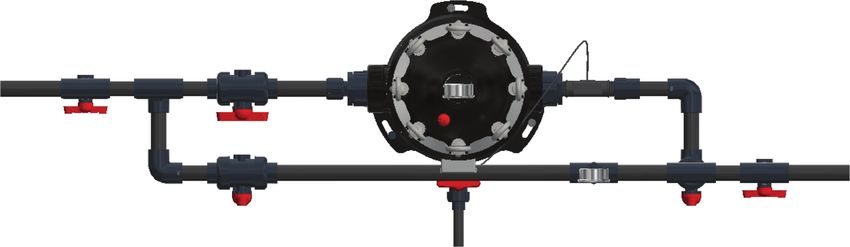
Installation Precautions
    NOTICE                                                                     System Diagram
•D
  o not install the system where it would block access to the
 water heater, main water shutoff, water meter, or electrical
 panels.                                                                                                E                      F
                                                                                  B
• Install the system in a place where water damage is least likely
   to occur if a leak develops.
•S
  ystem is intended to be installed on the cold water line ONLY.
 Do not use hot water supply or feed the system with water                                                                                           G
 temperatures exceeding what is specified in the Operating
 Parameters or system damage could occur.
•D
  o not install if your water lines are susceptible to water ham-
 mer. Correct water hammer issues first before system installa-
 tion.
•S
  ystem to be used with municipal or well water sources prop-
                                                                                             I
 erly treated and tested on a regular basis to ensure suitable
 and non-adverse water conditions, including bacteriological
 safe quality.
• System is intended to be installed indoors.
•F
  ilter system must be protected against direct sunlight, rain,
 moisture, freezing temperatures, frost, snow, sleet and ice.
 Exposure to these elements can damage the system and lead                                        C                                          A
 to water damage or damage to the electronics.
•S
  ystem must be installed vertically and on a flat level surface
 that is sturdy enough to support the weight of the system
 while it is in operation.                                                                                                          J
•C
  onstruction of a system bypass including inlet, outlet and                                                                                    G
 bypass valves is recommended to facilitate servicing of the
 system.
•T
  he filter cartridge recommended for use with this system car-
 ries a limited service capacity as indicated by the volumetric
 flow monitor. Ineffective reduction of contaminants, changes in                                                                             H
 taste, odors, color and/or flow of the water being filtered can
 occur if filter cartridge is not changed as required.                                D
                                                                                                                                         K
•M
  ake certain that installation complies with all state and local
 laws and regulations.
•T
  he full weight of the piping and valves must be supported by
 pipe hangers or other means.
                                                                          Diagram Identification
Contents of Filter System                                                  ITEM           DESCRIPTION
                                                                           A              Filter Housing
Please make sure all of the items listed below are contained
in the box. If any of the items are missing please contact                 B              Lead/PFOA/PFOS/Cyst/Chlorine Reduction Filter Cartridge
your Watts Representative or Watts Customer Service at                     C              Inlet Water Connection Plumbing Adaptor
978-689-6066 prior to installing.                                          D              Optional Outlet Water Connection
•    Filter Housing                                                        E              Inlet Water Pressure Gauge
•    Filter Cartridge (Is factory preinstalled inside filter housing)      F              Pressure Relief Button
•    Inlet Water Pressure Gauge                                            G              Volumetric Flow Monitor and 1" Inline Flow Meter
                                                                           H              Outlet Water Connection Plumbing Adaptor
•    Plumbing Adaptors 2" PVC (2 Each)
                                                                           I              2" Male Glue X 1" FNPT PVC Bushings (2 Each)
•    Plumbing Adaptor O-rings (2 Each)
                                                                           J              Drain Water Connection (Plugged)
•    Plumbing Adaptor Nuts (2 Each)                                        K              Anchor Mounting Bolts Not Shown (X3)
•    2" Male Glue X 1" FNPT PVC Bushings (2 Each)
•    Volumetric Flow Monitor Display and 1" Inline Flow Meter
•    ⁄ " Concrete Anchor Bolts (3 Each)
     38

IOM-WQ-BB-S100 2130                                               EDP# 68110146                                                         © 2021 Watts     7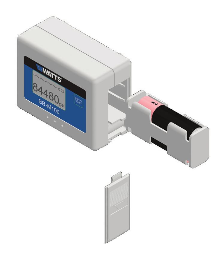
Installation
Recommended Tools for Installation                                        Step 5 - Remove foam packaging pieces: A. from lid of filter
                                                                          housing and B. from top of filter cartridge. To remove foam piece
• Small knife to cut box tape                                             B it may be necessary to remove filter cartridge by rotating fil-
• Variable speed hammer drill and 3⁄8" concrete drill bit                ter cartridge ½ rotation counterclockwise, then lifting up on the
  (If installing on concrete)                                             filter cartridge. Once exposed, remove foam piece B. For addi-
                                                                          tional information on filter cartridge removal see Filter Cartridge
• Adjustable wrench                                                       Replacement Procedure in this manual.
• General plumbing tools for your specific plumbing type
• Plumbing Tape
• Silicone O-ring lubricant
                                                                                  REMOVE FOAM
                                                                                  FROM TOP LID &
Preparing the System for Installation                                             DISCARD

    NOTICE
The Watts Model BB-S100 is factory packaged with inner pack-
aging for added protection. This internal packaging must be
removed from the system before beginning installation.                                                                         REMOVE FOAM
                                                                                                                               STRIP FROM
                                                                                                                               HOUSING &
                                                                                                                               DISCARD
Step 1 - Remove the packaging bands from the system box
and open the top flaps of the box. Remove the black foam pack-                      REMOVE
aging pad.                                                                       TAGS 2 (EA)
                                                                                   "REMOVE
                                                                                      FOAM
                                                                                    INSERT"
Step 2 - Remove the upper cardboard packaging tray and
locate the pressure gauge, flow monitor with flow meter box
marked “BB-M100”, system manual, 2" PVC plumbing adaptors
(2 each), plumbing adaptor O-ring (2 each) 2" Male Glue X 1"
FNPT PVC plumbing bushings (2 each), and anchor mounting
bolts (3 each) all packaged within the cardboard tray. Keep these
components in a safe location for later installation steps.

Step 3 - Lift up on the system box to remove it from the filter
system. Then lift filter system out of its bottom box and set it ver-
tically on the floor.
                                                                          Step 6 - Ensure        filter housing lid O-ring is properly seated on
                                                                                          INLET PRESSURE
                                                                          top of filter housing   and   reinstall filter housing lid. Swing the eye-
                                                                                                     GAUGE
Step 4 - Note the two instruction tags at the top of the filter           bolts into theTOupward      position, and tighten nuts hand tight in an
                                                                                          FACE AT PROPER
                                                                                        ANGLE FOR PROPER
housing instructing the installer to “Remove Foam Packaging”              opposing style    pattern.   Continue tightening nuts in this opposing
                                                                                            VISUALIZATION
located inside the filter housing. To remove filter housing lid, loos-    pattern until all are fully hand tight.
en all eyebolt nuts counterclockwise, allow bolts to swing and
relax downward, then lift up on filter housing lid.                                                               1
                                                                                                       7                       5

                                                                                                   4                                3
                                                                                                           6      2      8

                                                SLIGHTLY UNSCREW
                                                EYE BOLT NUT TO
                                                SWIVEL BOLT DOWN

8      IOM-WQ-BB-S100 2130                                                 A 68110146
                                                                         EDP#                                                           © 2021 Watts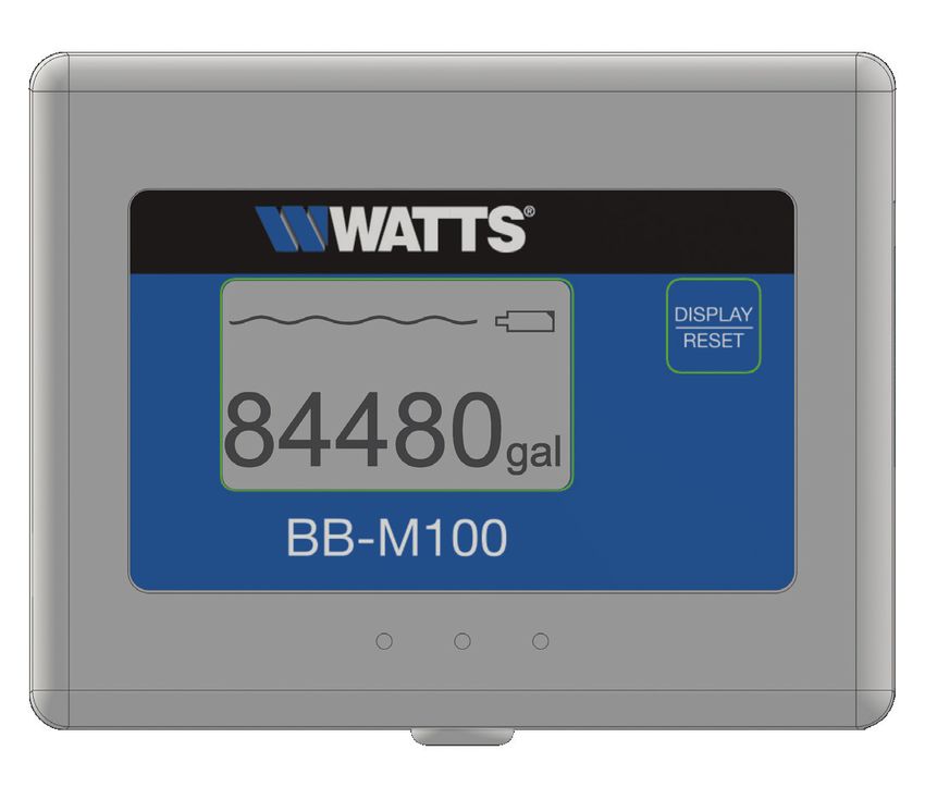
Installation
Note: Locate the components identified in previous “Preparing         Step 4 - Apply plumbing tape to the inlet thread of the 1"
the System for Installation” Step 2 for use in this section.          inline flow meter. An arrow on the flow meter indicates the direc-
                                                                      tion of flow. Apply plumbing tape to the outlet thread of 1" flow
See Installation Diagrams on page 12 for additional                   meter if required by the outlet plumbing method used. Insert flow
information.                                                          meter into system outlet plumbing port with the arrow pointing in
                                                                      the direction of flow. Hand tighten only, clockwise, DO NOT use
                                                      A               wrenches.
Step 1 - The system must be installed in a vertical position.
Place the system in the desired location. Make sure that the
mounting surface is level and sturdy enough to support the
weight of the system while in operation.

Step 2 - Prepare the filter housing for installation by first
unthreading and removing the union nuts of both the inlet and
outlet ports in a counterclockwise motion. Install the plumbing
adaptor O-ring into the O-ring grove of each inlet and outlet port,
attach plumbing adaptors and reattach union nuts tightening
hand tight only, DO NOT use wrenches. DO NOT use thread
sealant of any kind on the union threads. Use only silicone lubri-                                              INSTALL AS SHOWN
                                                                                                                & APPLY PLUMBING TAPE
cant on O-rings.                                                                                                TO PREVENT LEAKS

Note: System has an optional outlet port to accommodate dif-
                                                                      Step 5 - Insert 2 AA alkaline batteries into flow monitor.
                                                                      Monitor will turn ON once batteries are installed.
ferent plumbing arrangements. Outlet plumbing adaptor can be
relocated to optional outlet port if desired.

Step 3 - Using a primer and glue system approved for pres-
surized PVC potable water plumbing applications, install the 2"
Male Glue X 1" FNPT PVC plumbing bushings into the inlet and
outlet plumbing adaptors.

                                                                      Step 6 - Apply double sided tape to flow monitor mounting
                                                                      bracket. Press hold bracket against desired mounting location for
                                                                      10 seconds. Mounting surface must be clean and dry. Insert flow
                                                                      monitor into mounting bracket.

                                                                                 DO NOT INSTALL
                                                                               ANY HARDWARE ON
                                                                          BRACKET TO AVOID ANY
                                                                              DAMAGE TO SYSTEM
                                                                            (WARRANTY VOIDED IF
                                                                          HARDWARE IS PRESENT)

                                          DETAIL B

IOM-WQ-BB-S100 2130                                           EDP# 68110146                                          © 2021 Watts       9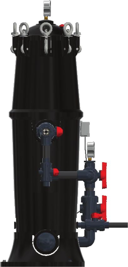
Installation
Step 7 - Connect the flow monitor cable to flow meter cable.             Step 12 - Construct outlet plumbing line from flow meter
                                                                         outlet port of system and connect to supply line entering home.
                                                                         Include an outlet water isolation valve (user supplied) in the outlet
                                                                         line and close it. Also install an outlet pressure gauge in this line.

                                                                         Step 13 - Construct a bypass plumbing line around the sys-
                                                                         tem. Include a bypass valve (user supplied) in the bypass line and
                                                                         close it.

                                                                         Step 14 - Remove ½" NPT system drain port plug (item #6
                                                                         and #7) from filter housing counterclockwise.

                                        SNAP CONNECTORS
                                        TOGETHER, CLICK SOUND
                                        WHEN PROPERLY
                                        INSTALLED

                             DETAIL C

Step 8 - Apply plumbing tape to the threads of the pressure                                    7
gauge and insert into the gauge port of the filter housing lid. Use
a wrench to tighten clockwise, Do Not twist on the gauge case.                                       6

                                                     DETAIL A

               INSTALL INLET PRESSURE
          GAUGE & APPLY PLUMBING TAPE
                 TO PREVENT ANY LEAKS

             INLET PRESSURE GAUGE                                                   DETAIL A
          TO FACE AT PROPER ANGLE
         FOR PROPER VISUALIZATION
                                                                         Construct a drain line with shut off valve using 1/2" PVC plumb-
                                                                         ing (user supplied) so the system can be drained of water during
                                                                         filter cartridge changes. Drain line must route to a drain recep-
                                                                         tacle (i.e., floor drain or drain pipe) where drain water will not
                                                                         cause personal injury or property damage. Close the drain valve.
                                                                         Follow all local building codes for drain line construction. Leave
                                                                         an air gap of at least 4" at the end of the drain line. See page 12
                                                                         Installation Diagrams for additional information.

                                                                         Step 15 - Using drill and 3/8 drill bit, anchor system to floor
                                                                         with mounting hardware provided. If mounting surface is other
                                                                         than concrete, installer must provide appropriate mounting hard-
                                                                         ware.
Step 9 - Turn off the main water supply to the home and open
an inside Faucet, both hot and cold side, to relieve any pressure
within the plumbing system.                                              Step 16 - For installations where the system is installed within
                                                                         a metal plumbing system, install a metal bonding strap across
                                                                         metal inlet and outlet plumbing lines to maintain electrical conti-
Step 10 - Turn off water heater(s).                                      nuity.

Step 11 - Construct inlet plumbing line from domestic cold
water source and connect to inlet plumbing port on system.
Include an inlet water isolation valve (user supplied) in the supply
line and close it.
     A

                                                                C
10       IOM-WQ-BB-S100 2130                                           EDP# 68110146                                              © 2021 Watts
System Start Up Procedure
Step 1 - Turn on main water supply to home.
Flow Wave Indicator- Indicates water flow
Step 2 - Open inlet isolation valve to the ¼ open position. through system.
Step 3 - Press the red pressure relief button on top of filter
housing lid to bleed air from the system while it is filling with Low Battery Indicator- Alarm Icon illuminates
water. Stop pressing pressure relief button once water flow from when battery power is low and alarm will
pressure relief is visible. sound. Replace batteries to clear alarm
conditions.
! WARNING
Change Batteries ONLY when screen is dor-
mant and NO water is flowing through the
flow meter. If water is flowing and screen is on
when batteries are changed, the last usage
volume will not be saved.
Step 4 - Fully open inlet and outlet isolation valves and allow
water to flow from hot and cold side of faucets until all air has
been purged from the plumbing system.
Battery Compartment- 2- AA Alkaline
Step 5 - Check for leaks and repair as needed. Batteries.
Step 6 - Close hot side faucet and allow water to flow from
cold side faucet at full flow for 10 minutes to properly flush new
Display/Reset Button- Can be pressed for 1
filter cartridge to prepare it for use. Turn off faucet cold side.
second while display is dormant to view gal-
lons remaining. Press and hold for 6 seconds
Step 7 - Turn on water heater(s) to reset display back to 84480 Gallons and
The system is now ready for use. to clear alarm after filter cartridge is changed.
NOTICE
Volume Remaining- Counts down from full
Check frequently over the next 24 hours to ensure no leaks are capacity to “0” gallon. Full Capacity is 84480
present Gallons. Audible alarm will sound and screen
will flash “0 gal” when filter cartridge change
Volumetric Flow Monitor Operation is required.
The flow monitor and inline flow meter that comes with this sys-
tem is a volumetric flow device that records water volume usage
and sounds an alert when the filter cartridge has reached its Display Screen- Activates only when water is
rated gallon capacity. flowing through system. Display is dormant
after 10 seconds of no water flow.
IOM-WQ-BB-S100 2130 EDP# 68110146 © 2021 Watts 11
CInstallation Diagrams
INLET PRESSURE GAUGE
Front View
INLET UNION
ISOLATION VALVE
OUTLET PRESSURE GAUGE
INLET
1" INLINE
FLOW METER
OUTLET
SAMPLE PORT
BYPASS VALVE
(NORMALLY CLOSED)
SAMPLE PORT
OUTLET UNION
ISOLATION VALVE
OPTIONAL
OUTLET
FRONT VIEW
WATER DRAIN
UNFILTERED
TopTOP
View
VIEW
VOLUMETRIC FLOW
MONITOR
Side View
SIDE VIEW
12 IOM-WQ-BB-S100 2130 EDP# 68110146 © 2021 WattsFilter Cartridge Replacement Procedure
Replacement Carbon Block Filter Cartridge: Step 7 - Remove new filter cartridge from packaging bag.
Grip the handle on top of the filter cartridge and insert filter car-
Model Number BB-C100 tridge into filter housing. Lower filter cartridge into filter housing,
Ordering Code 7100980 pushing down while rotating clockwise until filter cartridge comes
to a positive stop.
Replace filter when flow monitor capacity
alarm sounds and “0” Gallons remain on
flow monitor
Step 1 - Turn off inlet and outlet isolation valves and open
an inside faucet, both hot and cold side, to relieve any pressure
within the plumbing system.
Step 2 - Press red pressure relief button on top of filter hous-
ing lid until water stops flowing from button and the pressure
gauge on top of filter housing lid shows “0” PSI.
Step 3 - Open drain valve and completely drain water from fil-
ter housing. Drain line must route to a drain receptacle (i.e., floor
drain or drain pipe) where drain water will not cause personal
injury or property damage.
Step 4 - Loosen eye bolt nuts on top of filter housing and
remove lid.
Step 8 - Ensure lid O-ring is properly seated on top of filter
Step 5 - To remove filter cartridge from filter housing, grip the housing and reinstall filter housing lid (replace O-ring if damaged-
handle on top of the filter cartridge, turn counterclockwise then Ordering Code 68100619). Swing the eyebolts into the upward
lift filter cartridge up and out of filter housing. position, and tighten nuts hand tight in an opposing style pattern.
Continue tightening nuts in this opposing pattern until all are fully
hand tight. (See Preparing System for Installation Step 6)
Step 9 - Press and hold DISPLAY / RESET button on flow
monitor for 6 seconds to reset the gallon capacity remaining to
84480 Gallons.
Follow System Start Up Procedure steps 2-6 to prepare the sys-
tem for operation.
The system is now ready to use.
Step 6 - Inspect inside of filter housing for debris and clean as
necessary.
IOM-WQ-BB-S100 2130 EDP# 68110146 © 2021 Watts 13Replacement Parts
15
12
13
11
18
14
10
9
8
17
2
17 3
5
16
2
1 2
1
3
4
A
16
2
2
5
17 5
7
6
DETAIL A
14 IOM-WQ-BB-S100 2130 EDP# 68110146 © 2021 WattsReplacement Parts
ITEM # ORDERING DESCRIPTION
CODE
1 68100610 Filter Housing Coupler
2 68100611 O-ring for Filter Housing Coupler
3 68100608 Plumbing Adapter 2" PVC Grey
4 68100614 Filter Housing Coupler Cap 2" PVC Grey
5 68100618 Plumbing Adapter Union Nut
6 68100613 Drain Plug 1/2" NPT
7 68100612 O-ring for Drain Plug
BB-H100 Replacement Filter Housing Includes Plumbing Adapters, Union Nuts, Pressure Gauge,
8 7100979
Filter Housing Lid and O-rings
9 68100615 Eye Bolt
10 68100619 Filter Housing Lid O-ring
11 68100616 Filter Housing Lid -Does Not Include Pressure Gauge
12 68100620 Pressure Relief Button Red
13 68100622 Spring for Pressure Relief Button
14 68100623 Locking Pin Stem Red for Pressure Relief Button
15 68106170 Pressure Gauge 0-200 PSI 1/4" Bottom Mount
16 7100978 2" Male Glue X 1" FNPT Plumbing Bushing PVC Grey
17 7100977 Model # BB-M100 Volumetric Flow Monitor With 1" Inline Flow Meter 84480 Gallon Capacity
Model # BB-C100 Carbon Block Filter Cartridge for the Reduction of Lead, PFOA/PFOS, Cysts, and
18 7100980
Chlorine Taste & Odor
For replacement components and service please contact the Watts Dealer/Distributor that installed the system. If Dealer/
Distributor cannot be reached, contact Watts Customer Service at 978-689-6066.
IOM-WQ-BB-S100 2130 EDP# 68110146 © 2021 Watts 15Troubleshooting
TROUBLESHOOTING
ISSUE POSSIBLE CAUSE CORRECTIVE ACTION
Contaminant(s) present in Filter cartridge has exceeded its capacity Replace filter cartridge and reset flow monitor
outlet water O-ring damage on filter cartridge Replace filter cartridge and reset flow monitor
Filter cartridge is broken or defective Replace filter cartridge and reset flow monitor
Bypass valve is open Close bypass valve
System is too small for the application Ensure water flow does not exceed systems rated GPM
Volumetric flow monitor is Batteries need to be replaced Replace batteries, replace filter cartridge and reset flow monitor*
not tracking water usage Foreign debris in flow meter Clean meter of foreign debris, replace filter cartridge and reset flow monitor
Flow monitor cable is not properly connected to meter Check cable connection, replace filter cartridge and reset flow monitor
Install flow meter with arrow pointing in the direction of flow, replace filter cartridge
Flow meter is installed backwards
and reset flow monitor
Bypass valve is open Close bypass valve
Alarm does not clear when Defective flow monitor Replace flow monitor and replace filter cartridge
flow monitor is reset Battery power is low Replace batteries*
Water leak at inlet/outlet O-ring is damaged or not seated properly Replace plumbing adaptor O-ring
plumbing adaptor Union nuts are loose Fully hand tighten union nuts
Water leak at filter housing lid O-ring is damaged or not seated properly Replace filter housing lid O-ring
Eye bolt nuts are loose Fully hand tighten eyebolt nuts in an opposing pattern
Water leaks from pressure
Damaged O-ring or foreign debris in pressure relief assembly Clean pressure relief valve and replace if required
relief button
Low pressure at outlet Install a 5 micron pre-sediment filter before system, replace filter cartridge and reset
Filter cartridge clogged with sediment
flow monitor
System is too small for the application Ensure water flow does not exceed system's rated GPM
White or milky colored water Fully purge air from system using pressure relief button and run water through system
Air in filter system
from system until water runs clear
! WARNING
*Change Batteries ONLY when screen is dormant and
NO water is flowing through the flow meter. If water is
flowing and screen is on when batteries are changed,
the last usage volume will not be saved.
16 IOM-WQ-BB-S100 2130 EDP# 68110146 © 2021 WattsPerformance Data Sheet
Certified Substance Reduction Contact:
RECOMMENDED REPLACEMENT PARTS AND CHANGE INTERVAL: USA
Depending on incoming feed water conditions, replacement gallon capacity Watts
may vary. 815 Chestnut Street
North Andover, MA 01845-6098
Description
Phone: 978-689-6066
Big Bubba BB-S100 Complete Whole Home Solution for the Reduction of
Fax: 978-975-8350
Lead, PFOA/PFOS, Cysts, and Chlorine Taste & Odor
Watts.com
System Model/Part Number
BB-S100 / 7100976 Canada
Capacity Watts
84,480 Gallons / 319,791 Liters 5435 North Service Road
Replacement Filter Cartridge Burlington, ON L7L 5H7
Carbon Block Filter Cartridge for the Reduction of Lead, PFOA/PFOS, Cysts, Phone: 888-208-8927
and Chlorine Taste & Odor Model Number BB-C100 / Part Number 7100980 Fax: 905-481-2316
Watts.ca
Minimum/Maximum Operating Water Temperature
34 to 125°F / 1 to 52°C (125°F / 52°C at 80psi maximum pressure)
Minimum/Maximum Water Pressure
25psi to 125psi /1.75 Kg/cm2 to 8.78 Kg/cm2 For Purchases Made In Iowa
Rated Service Flow
4 GPM (15 LPM) Buyers Name:________________________________________
Pressure Drop of System at Rated Service Flow Date:_______________________________________________
10psig
Sellers Name:________________________________________
BB-S100 system has been certified by IAPMO R&T against NSF/
ANSI 42 and 53 for the reduction of substances listed below. The Date_______________________________________________
concentration of the indicated substances in water entering the The seller shall retain the signed PDS on file at the seller's place of
system was reduced to a concentration less than or equal to the business for at least two years.
permissible limit for water leaving the system, as specified in NSF/
ANSI 42 and 53. The system is certified to CSA B483.1 and NSF/
ANSI 372 for Lead Free compliance.
Treated water from system should be tested at regular intervals to
ensure quality and safety at point of use.
SUBSTANCE AVERAGE INFLUENT NSF/ANSI INFLUENT PERCENT REDUCTION AVERAGE % REDUCTION @ PEAK FLOW &
CHALLENGE CONCENTRATION REQUIREMENT/MAXIMUM FLOW RATE GPM (LPM) % REDUCTION
PERMISSIBLE PRODUCT OF LEAD
WATER CONCENTRATION
NSF/ANSI 42 — Aesthetic Effects
Chlorine 2.0 mg/L 2.0 mg/L ± 10% ≥ 50% 97.90% @4 GPM (15 lpm) 7 GPM (26.4 lpm) @
NSF/ANSI 53 — Health Effects 99.62% reduction
Cyst 126,000/L Minimum 50,000/L > 99.95% 99.97% @4 GPM (15 lpm)
Lead pH 6.5 0.15 mg/L ± 10% 0.15 mg/L ± 10% 0.005 mg/L 99.62% @4 GPM (15 lpm) (*) >74,000 gallons
Lead pH 8.5 0.15 mg/L ± 10% 0.15 mg/L ± 10% 0.005 mg/L 99.62%@4 GPM (15 lpm) at 8 GPM (280,090
PFOA/PFOS .0015 mg/L ±10% .0015 mg/L ± 10% 0.00007 mg/L 98.26% @4 GPM (15 lpm) Liters @ 26.4 lpm)
Not all water will contain contaminants listed. Testing performed under standard laboratory conditions; actual performance may vary. Filter system usage must comply with all state and
local laws. Filter system is only to be used with cold water. Do not use with water that is microbiologically unsafe or of unknown quality without adequate disinfection before or after
the system. Systems certified for cyst reduction may be used on disinfected water that may contain filterable cysts. Flush new filter cartridge for 10 minutes to prepare it for use. Spent
adsorption media shall not be regenerated and used.
Non-Certified Substance Reduction*
SUBSTANCE AVERAGE INFLUENT INTERMITTENT PEAK FEED FLOW ESTIMATED GALLON CAPACITY @ ESTIMATED NEW CARTRIDGE
CONCENTRATION RATE GPM (LPM) INTERMITTENT PEAK FEED FLOW PERCENT REDUCTION OF
RATE SUBSTANCE @ INTERMITTENT
PEAK FLOW RATE
Chlorine 2.0 mg/L Free Chloine 13 GPM (49.2 lpm) 264,000 Gallons (999,348 liters) 90%
Chloramine 3.0 mg/L Free Chloramine 7 GPM (26.4 lpm) 132,000 Gallons (499,674 liters) 85%
*Claims are not performance tested or certified by IAPMO. Performance claims are based on independent laboratory and manufacturer’s internal test data.
Actual performance is dependent on influent water quality, flow rates, system design and application. Results may vary.
Refer to Owner’s Manual and Installation instructions for installation, operation, maintenance, and warranty information.
IOM-WQ-BB-S100 2130 EDP# 68110146 © 2021 Watts 17Volumetric Flow Monitor Quick Reference Guide
Battery Life Indicator
Change Batteries ONLY when screen is dormant
and NO water is flowing through the flow meter.
Device Ready / Start: Display ON & meter DISPLAY / RESET
shows 84,480 gallons remaining Display: Press for 1 second anytime
Gallons Count / Flow Icon displayed only the display is dormant to view current
when water is flowing. gallons remaining.
End of Filter Life Alert: Display Flashes Reset: End of filter life, replace filter.
“0 gal” Plus Audible Alarm Press & hold for 6 seconds to reset to
full capacity (84,480 gallons).
18 IOM-WQ-BB-S100 2130 EDP# 68110146 © 2021 WattsVolumetric Flow Monitor Quick Reference Guide
1 3
a
b
Insert Batteries a. Add double sided tape to mounting bracket and mount to
desired area.
b. Connect cable to flow meter.
2
Install the flow meter on the filtered water outlet with arrow
pointing in direction of flow.
IOM-WQ-BB-S100 2130 EDP# 68110146 © 2021 Watts 19Limited Warranty: Watts (the “Company”) warrants each product to be free from defects in material and workmanship under normal usage for a period of one year from the date of original shipment.
In the event of such defects within the warranty period, the Company will, at its option, replace or recondition the product without charge.
THE WARRANTY SET FORTH HEREIN IS GIVEN EXPRESSLY AND IS THE ONLY WARRANTY GIVEN BY THE COMPANY WITH RESPECT TO THE PRODUCT. THE COMPANY MAKES NO OTHER
WARRANTIES, EXPRESS OR IMPLIED. THE COMPANY HEREBY SPECIFICALLY DISCLAIMS ALL OTHER WARRANTIES, EXPRESS OR IMPLIED, INCLUDING BUT NOT LIMITED TO THE IMPLIED
WARRANTIES OF MERCHANTABILITY AND FITNESS FOR A PARTICULAR PURPOSE.
The remedy described in the first paragraph of this warranty shall constitute the sole and exclusive remedy for breach of warranty, and the Company shall not be responsible for any incidental, special
or consequential damages, including without limitation, lost profits or the cost of repairing or replacing other property which is damaged if this product does not work properly, other costs resulting
from labor charges, delays, vandalism, negligence, fouling caused by foreign material, damage from adverse water conditions, chemical, or any other circumstances over which the Company has no
control. This warranty shall be invalidated by any abuse, misuse, misapplication, improper installation or improper maintenance or alteration of the product.
Some States do not allow limitations on how long an implied warranty lasts, and some States do not allow the exclusion or limitation of incidental or consequential damages. Therefore the above
limitations may not apply to you. This Limited Warranty gives you specific legal rights, and you may have other rights that vary from State to State. You should consult applicable state laws to
determine your rights. SO FAR AS IS CONSISTENT WITH APPLICABLE STATE LAW, ANY IMPLIED WARRANTIES THAT MAY NOT BE DISCLAIMED, INCLUDING THE IMPLIED WARRANTIES OF
MERCHANTABILITY AND FITNESS FOR A PARTICULAR PURPOSE, ARE LIMITED IN DURATION TO ONE YEAR FROM THE DATE OF ORIGINAL SHIPMENT.
USA: T: (978) 689-6066 • F: (978) 975-8350 • Watts.com
Canada: T: (888) 208-8927 • F: (905) 481-2316 • Watts.ca
Latin America: T: (52) 55-4122-0138 • Watts.com
IOM-WQ-BB-S100 2130 EDP# 68110146 © 2021 WattsIOM-WQ-BB-S100
Manual de instalación, operación y mantenimiento
Big Bubba® Model BB-S100
Una solución completa de sistema para todo el hogar de reducción
del plomo, PFOA/PFOS, quistes, y el sabor y olor a cloro
Certificado por IAPMO R&T según las normas NSF y del ANSI 42 y 53 para
la disminución de afirmaciones verificadas y corroboradas por los datos de
pruebas como se especifica en la hoja de datos de rendimiento. El sistema
C ®
también está certificado según las norma CSA B483.1 y la norma 372 de la
NSF y el ANSI para el cumplimiento de la norma sin plomo.¡Felicidades por su compra de la solución completa de sistema para todo el hogar Watts BB-S100! Ha hecho una gran elección para proteger su hogar contra el plomo, PFOA/PFOS, quistes, y el sabor y olor a cloro. Este sistema es eficaz contra numerosos contaminantes y está cargado con características que incluyen un único cartucho filtrante remplazable de alta capacidad calificado para 84 480 galones (319 792 l) y un sistema de monitoreo de flujo volumétrico con alerta de cambio del cartucho filtrante. El sistema BB-S100 utiliza la robusta carcasa de filtro Watts Big Bubba®, un ícono de confianza del sector de la filtración de agua, por lo que puede confiar en que su sistema será duradero y fácil de mantener. ¡Gracias! El equipo de Watts La contaminación del agua potable con plomo y PFOA/PFOS es una preocupación importante de muchos consumidores por los problemas de salud que pueden ocasionar. Según la USEPA, el plomo puede causar problemas de comportamiento, aprendizaje y bajo coeficiente intelectual en los niños, así como problemas renales y cardiovasculares en adultos. Aunque los riesgos asociados con los productos químicos PFAS aún son ampliamente desconocidos, los estudios USEPA indican que la exposición a PFOS y PFOA (los productos químicos más producidos y estudiados) puede tener repercusiones reproductivas y de desarrollo, hepáticas y renales, e inmunológicas, así como causar tumores en animales de laboratorio. 22 IOM-WQ-BB-S100 2130 EDP# 68110146 © 2021 Watts
Introducción
  ! ADVERTENCIA
                 Lea este manual ANTES de utilizar el equipo.
                 No leer y seguir toda la información de seguridad y uso
                 puede provocar la muerte, lesiones personales graves,
   PIENSE        daños a la propiedad o daños al equipo.
   PRIMERO EN
  LA SEGURIDAD   Guarde este Manual para consultas posteriores.

Si tiene dudas sobre la instalación de su sistema Watts Filter,               Índice
póngase en contacto con un representante de Watts o consulte a un
plomero profesional.                                                          Descripción general . . . . . . . . . . . . . . . . . . . . . . . . . . . . . . . . . .  24
Es necesario que lea detenidamente todas las instrucciones                    Especificaciones del equipo . . . . . . . . . . . . . . . . . . . . . . . . . . . .  24
de instalación y la información de seguridad del producto                     Parámetros operativos y pautas para el agua de alimentación . .  24
antes de comenzar la instalación. EL INCUMPLIMIENTO DE                        Dimensiones y pesos . . . . . . . . . . . . . . . . . . . . . . . . . . . . . . . . .  25
LAS INSTRUCCIONES ADECUADAS DE INSTALACIÓN Y                                  Caudal y caída de presión  . . . . . . . . . . . . . . . . . . . . . . . . . . . . .  26
MANTENIMIENTO PODRÍA OCASIONAR UN FALLO EN EL
                                                                              Precauciones de instalación . . . . . . . . . . . . . . . . . . . . . . . . . . . .  27
PRODUCTO QUE PUEDE CAUSAR DAÑOS A LA PROPIEDAD,
LESIONES PERSONALES O LA MUERTE. Watts no se hace                             Contenido del sistema de filtración . . . . . . . . . . . . . . . . . . . . . . .  27
responsable de los daños resultantes de una instalación y/o                   Diagrama del sistema . . . . . . . . . . . . . . . . . . . . . . . . . . . . . . . . .  27
mantenimiento inadecuados. Las códigos locales de construcción                Preparación del sistema para la instalación  . . . . . . . . . . . . . . . .  28
o plomería pueden requerir modificaciones en la información
                                                                              Instalación  . . . . . . . . . . . . . . . . . . . . . . . . . . . . . . . . . . . . . . . . .  29
proporcionada. Es obligatorio que consulte los códigos locales
de construcción y plomería antes de realizar la instalación. Si la            Procedimiento de inicio del sistema . . . . . . . . . . . . . . . . . . . . . .  31
información no cumple con los códigos locales de construcción o               Funcionamiento del monitor de flujo volumétrico  . . . . . . . . . . . .  31
plomería, se deben seguir los códigos locales. Guarde el manual               Diagramas de instalación . . . . . . . . . . . . . . . . . . . . . . . . . . . . . .  32
para consultas posteriores.                                                   Procedimiento para remplazar el cartucho filtrante . . . . . . . . . . .  33
Consulte los parámetros de funcionamiento incluidos para garantizar           Piezas de repuesto . . . . . . . . . . . . . . . . . . . . . . . . . . . . . . . . . . .  34
un uso adecuado con su suministro de agua.
                                                                              Solución de problemas . . . . . . . . . . . . . . . . . . . . . . . . . . . . . . . .  36
                                                                              Hoja de datos de rendimiento  . . . . . . . . . . . . . . . . . . . . . . . . . .  37
Si este equipo, o cualquiera de sus piezas, se daña o necesita                Guía de referencia rápida del monitor de flujo volumétrico . . . . .  38
reparación, deje de usar el equipo y póngase en contacto con
un técnico experimentado inmediatamente.                                      Garantía limitada . . . . . . . . . . . . . . . . . . . . . . . . . . . . . . . . . . . . . 40

•	Utilice únicamente soldadura y fundente sin plomo para
   conexiones de soldadura de estaño, según lo requieran los
   códigos estatales, provinciales y federales.
•	Maneje todos los componentes del sistema con cuidado. No deje
   caer, arrastre ni invierta los componentes.
•	Asegúrese de que el piso debajo del sistema esté limpio, nivelado
   y lo suficientemente fuerte para soportar el sistema mientras está
   en funcionamiento.
•	Instale el sistema en un área protegida.
•	No intente tratar agua a más de 125 °F (51 °C) con el sistema.
•	Conecte siempre el sistema a la tubería principal de suministro de
   agua antes del calentador de agua.
•	No exponga el sistema a temperaturas bajo cero. El agua
   congelada en el sistema causa daños en el equipo.
•	No lo instale bajo la luz solar directa. Los rayos ultravioletas del sol
   pueden causar daños.
•	Es posible que se requiera un cartucho filtrante desechable de 5
   micrones como prefiltro de este sistema para evitar la obstrucción
   prematura del cartucho filtrante del sistema BB-S100 por
   sedimentos.
                                                                                 ! PRECAUCIÓN
  ! ADVERTENCIA
                                                                              Pruebe el agua periódicamente para verificar que el sistema
 No lo utilice con agua microbiológicamente insegura o de calidad
                                                                              funciona satisfactoriamente.
 desconocida sin desinfección adecuada antes o después del
 sistema. El sistema certificado para la reducción de quistes se
 puede utilizar con aguas desinfectadas que pudieran contener
 quistes filtrables.

IOM-WQ-BB-S100 2130                                                   EDP# 68110146                                                                © 2021 Watts                23
Descripción general Parámetros operativos y pautas
Gracias por comprar esta solución de sistema de tratamiento de
para el agua de alimentación
agua de calidad.
AVISO
Su nuevo sistema está equipado con un cartucho filtrante de
bloque de carbón de alta capacidad capaz de reducir el plomo, La instalación debe cumplir con los reglamentos estatales y locales
PFOA/PFOS, quistes, sedimentos, cloro y cloramina. Otra gran de plomería.
característica de este sistema es el monitor de flujo volumétrico
que le avisa cuando es necesario remplazar el cartucho filtrante
Revise las presiones de funcionamiento, las temperaturas
en función del consumo de agua. El sistema de filtración de agua
y las limitaciones de química del agua para garantizar la
BB-S100 proporciona agua limpia, clara y de excelente sabor
compatibilidad.
a toda su casa y posee una capacidad de filtración de 84 480
galones (319 792 l) para la reducción de plomo y PFOA/PFOS. El pH . . . . . . . . . . . . . . . . . . . . . . de 6.5 a 8.5
sistema está certificado para reducir el plomo (soluble e insoluble), Presión de agua mín./máx. . . . de 25 psi a 125 psi/172 kPa a
PFOA/PFOS, quistes, y cloro. 861 kPa
Este sistema está diseñado para la instalación en el punto de Temperatura mín./máx. . . . . . . del agua de 34 a 125 °F/de
entrada para el tratamiento de todo el hogar y para que sea fácil y 1 a 52 °C
cómodo de reparar. (125 °F/52 °C a una
presión máxima de 80 psi)
Cloro libre (máximo) . . . . . . . . . 2.0 mg/l
Mantenimiento del sistema Hierro (máximo) . . . . . . . . . . . . 0.3 mg/l
Manganeso (máximo) . . . . . . . 0.05 mg/l
Es importante cambiar el cartucho filtrante en el intervalo Aceite y H2S . . . . . . . . . . . . . . No se permiten en absoluto
recomendado que se indica en este manual. Muchos contaminantes
no se pueden detectar en el sabor. Además, otros malos sabores y Turbidez/sedimento . . . . . . . . . Prefiltre el agua de entrada con un
olores pueden hacerse evidentes con el tiempo si el cartucho filtrante filtro de sedimentos de 5 micrones
no se sustituye cuando es necesario. si el sedimento/turbidez impide
que el cartucho filtrante BB-S100
Si tiene alguna otra pregunta, llame a nuestro servicio de atención al
alcance su capacidad de volumen
cliente (978) 689-6066 o a su representante de Watts.
total
Requisitos eléctricos
del sistema. . . . . . . . . . . . . . . . 2 baterías alcalinas AA
Especificaciones del equipo Para obtener más información sobre las demás pautas, póngase
en contacto con su representante de Watts. El agua que no cumpla
Este sistema de filtración de agua Watts es completo y autónomo, con las pautas anteriores requerirá un tratamiento previo adicional.
con el cartucho filtrante preinstalado en la carcasa del filtro. Se
requiere cierto ensamblaje de luz para instalar adaptadores de
plomería, monitor de flujo volumétrico y caudalímetro en línea.
Revise las presiones de funcionamiento, las temperaturas y las
limitaciones de química del agua para garantizar la compatibilidad y
el rendimiento.
24 IOM-WQ-BB-S100 2130 EDP# 68110146 © 2021 WattsEspecificaciones del equipo
VISTA FRONTAL VISTA LATERAL
Dimensiones y pesos
N.º DE MODELO DIMENSIONES PESOS DE ENVÍO PESO OPERATIVO
A B C* D E
in mm in mm in mm in mm in mm lb kg lb kg
BB-S100 21.6 549 3.9 99 42.6 1082 14.2 361 22.3 566.4 64 29 123 56
*Deje un espacio libre de 36 in (91.44 cm) por encima de la parte superior del sistema para la sustitución del cartucho filtrante.
Todas las dimensiones son +/- 1 in (2.54 cm) y están sujetas a cambios sin previo aviso.
IOM-WQ-BB-S100 2130 EDP# 68110146 © 2021 Watts 25Especificaciones del equipo
N.º. DE MODELO DEL SISTEMA BB-S100
Temperatura de funcionamiento mínima/máxima* De 34 a 125 °F/1 a 52 °C (125 °F/52 °C a una presión máxima de 80 psi)
Presión de funcionamiento mínima/máxima* De 25 psi a 125 psi/172 kPa a 861 kPa
Caudal máximo continuo para la reducción de plomo y PFOA/PFOS** 4 gal/min (15 l/m)
Caudal máximo para la reducción de cloro*** 13 gal/min (49.2 l/m)
Caudal máximo para la reducción de cloramina*** 7 gal/min (26.4 l/m)
Tamaño/tipo de conexión de entrada y salida NPT de 1 in (2.54 cm)
Tamaño/tipo de conexión del puerto de drenaje de la carcasa de agua sin filtrar ½ in (1.77 cm) FNPT
Material del cuerpo de la carcasa del filtro Polipropileno reforzado con vidrio
Puerto del manómetro de entrada Latón reforzado FNPT de 1⁄4 in (0.63 cm)
Manómetro de entrada incluido Sí
Material de los pernos de giro (tapa) Acero inoxidable 304
Material de junta tórica (tapa) EPDM
Material de junta tórica (adaptadores de tuberías) EPDM
Clasificación nominal en micrones 0.5 micrones nominales
Se incluye el kit de anclaje de la carcasa del filtro Sí, anclajes para concreto de 3/8 in (0.95 cm) (X3)
Número de cartuchos filtrantes 1
Tipo de soporte de cartucho filtrante Bloque de carbón de absorción de plomo
Material y color de la tapa de extremo del cartucho filtrante Polipropileno reforzado con vidrio/verde
La tapa del extremo superior del cartucho filtrante incluye asa Sí
Material de la junta tórica del cartucho filtrante (dual) EPDM
Caída de presión máxima permitida del cartucho filtrante Caída de 40 psi
Tipo de pantalla del monitor de flujo LCD de 5 dígitos. Cuenta atrás volumétrica a “0”
Capacidad del monitor de flujo 84 480 galones (319 792 l) (reajustable/ no programable)
Indicación positiva de flujo Sí. Ícono de onda de flujo en la pantalla
Alarma del monitor de flujo a los “0” galones restantes Durante el flujo de agua: Imagen. Parpadeo de “0 galón” en la pantalla/audible. Alarma sonora
Fuente de alimentación del monitor de flujo 2 baterías alcalinas AA
Alarma de batería baja Sí. Ícono visual de batería baja y alarma sonora
Tipo de caudalímetro Medidor de flujo en línea de turbina
Tamaño y tipo de conexión del caudalímetro 1 in (2.54 cm) x 1 in (2.54 cm) MNPT
Material del cuerpo del caudalímetro Polímero reforzado con vidrio
*Las temperaturas y presiones mínimas y máximas de funcionamiento indicadas anteriormente se aplican al sistema completo, así como a todos los componentes individuales, incluidos
la carcasa del filtro, el cartucho filtrante y el monitor/medidor de flujo volumétrico.
** Consulte la sección Reducción de sustancias certificadas para obtener afirmaciones específicas sobre el flujo y la reducción.
***Las afirmaciones no han sido probadas ni certificadas por la IAPMO. Las declaraciones de rendimiento se basan en datos de pruebas internas de laboratorios y fabricantes
independientes. El rendimiento real depende de la calidad del agua prefiltrada, los caudales, el diseño del sistema y la aplicación. Los resultados pueden variar. Consulte la sección
Reducción de sustancias certificadas para obtener afirmaciones certificadas sobre el flujo de cloro y la reducción.
Caudal y caída de presión
Flow Ratey and
Caudal Pressure
caída Drop
de presión
30 Baja caída de presión
(psi)
25
Drop (psi)
El sistema BB-S100 de Watts
20
de presión
utiliza un gran cartucho filtrante de
15
bloque de carbón de alta capacidad
Pressure
10
para garantizar el mayor grado de
Caída
5
rendimiento, al tiempo que ofrece el
0
1 2 3 4 5 6 7 8 9 10 11 12 caudal más alto posible con la menor
Flow Rate
Caudal (GPM)
(gal/min) caída de presión posible.
Prueba de caída de presión
realizada en las instalaciones de
Watts en Peoria, AZ, utilizando agua
a aproximadamente 73 °F. Los
resultados de la prueba reflejan el
nuevo caudal del cartucho filtrante y
el rendimiento de la caída de presión.
26 IOM-WQ-BB-S100 2130 EDP# 68110146 © 2021 WattsPrecauciones de instalación
AVISO Diagrama del sistema
• No instale el sistema en lugares en los que pudiera bloquear el
acceso al calentador de agua, la llave de paso principal de agua,
el medidor de agua o los paneles eléctricos. E F
• Instale el sistema en un lugar donde sea menos probable que se B
produzcan daños causados por el agua en caso de fugas.
• El sistema está diseñado para instalarse ÚNICAMENTE en la línea
de agua fría. No utilice el suministro de agua caliente ni alimente G
el sistema con temperaturas de agua superiores a lo especificado
en los parámetros de funcionamiento o podrían producirse daños
en el sistema.
• No lo instale si sus líneas de agua son susceptibles a golpes de
ariete. Antes de instalar el sistema, corrija los problemas de golpe
de ariete.
• El sistema se debe usar con fuentes de agua municipales o de I
pozo adecuadamente tratadas y probadas periódicamente para
garantizar condiciones de agua aptas y no adversas, lo que
incluye la calidad bacteriológica segura.
• El sistema está diseñado para instalarse en interiores.
• El sistema de filtración debe protegerse contra la luz solar directa,
la lluvia, la humedad, las temperaturas bajo cero, la escarcha, la
nieve, el aguanieve y el hielo. La exposición a estos elementos C A
puede dañar el sistema y provocar daños causados por el agua o
averías en los componentes electrónicos.
• El sistema debe instalarse verticalmente y en una superficie
plana y nivelada que sea lo suficientemente resistente como para J
soportar el peso del sistema mientras está en funcionamiento.
• Se recomienda la construcción de una derivación del sistema, G
incluidas las válvulas de entrada, salida y derivación, para facilitar
el mantenimiento del sistema.
• El cartucho filtrante recomendado para su uso con este sistema
tiene una capacidad de servicio limitada, tal como indica el
monitor de flujo volumétrico. Puede producirse una reducción H
ineficaz de los contaminantes, cambios en el sabor, olores, color D
y/o flujo del agua filtrada si el cartucho filtrante no se reemplaza
según sea necesario. K
• Cerciórese de que la instalación cumpla con todas las leyes y
reglamentos estatales y locales.
• El peso total de las tuberías y válvulas debe apoyarse en soportes
para tubería o por otros medios.
Identificación del diagrama
ELEMENTO DESCRIPCIÓN
Contenido del sistema de filtración A Carcasa del filtro
Asegúrese de que todos los elementos que se enumeran a B Cartucho filtrante de reducción de plomo/PFOA/PFOS/quistes/cloro
continuación estén contenidos en la caja. Si falta alguno de C Adaptador de tuberías para conexión de agua de entrada
los elementos, póngase en contacto con su representante D Conexión de agua de salida opcional
de Watts o con el servicio de atención al cliente de Watts E Manómetro de agua de entrada
llamando al 978-689-6066 antes de la instalación.
F Botón de alivio de presión
• Carcasa del filtro G Monitor de flujo volumétrico y caudalímetro en línea de 1 in (2.54 cm)
• Cartucho filtrante (está preinstalado de fábrica en el interior de H Adaptador de tuberías de conexión de agua de salida
la carcasa del filtro) Bujes de enlace macho FNPT de PVC de 2 in (5 cm) X 1 in (2.54 cm) (2
I
• Manómetro de entrada de agua unidades)
• Adaptadores de tuberías de 2 in (5 cm) de PVC (2 unidades) J Conexión de agua de drenaje (conectada)
• Juntas tóricas del adaptador de tuberías (2 unidades) K No se muestran los pernos de montaje del anclaje (X3)
• Tuercas adaptadoras para tuberías (2 unidades)
• Bujes de enlace macho FNPT de PVC de 2 in (5 cm) X 1 in
(2.54 cm) (2 unidades)
• Pantalla de monitor de flujo volumétrico y caudalímetro en línea
de 1 in (2.54 cm)
• Pernos de anclaje para concreto de 3 ⁄8in (0.95 cm) (3 unidades)
IOM-WQ-BB-S100 2130 EDP# 68110146 © 2021 Watts 27You can also read