For the integration of fluctuating renewable energy - David Connolly University of Limerick www.cpi.ul.ie 17 August 2009 ...
←
→
Page content transcription
If your browser does not render page correctly, please read the page content below
A Review of Energy Storage Technologies
   For the integration of fluctuating renewable energy

                   David Connolly
                University of Limerick

                 david.connolly@ul.ie
                    www.cpi.ul.ie

                    17 August 2009
                       Version 3
This review was carried out as part of David Connolly’s Ph.D. project, which
was supervised by Dr. Martin Leahy from the University of Limerick.
Print DoubleSided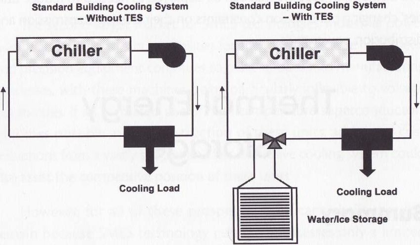
A REVIEW OF ENERGY STORAGE TECHNOLOGIES August 17, 2009

Abstract
A brief examination into the energy storage techniques currently available was carried out. These are Pumped‐
Hydroelectric Energy Storage (PHES), Underground Pumped‐Hydroelectric Energy Storage (UPHES),
Compressed Air Energy Storage (CAES), Battery Energy Storage (BES), Flow Battery Energy Storage (FBES),
Flywheel Energy Storage (FES), Supercapacitor Energy Storage (SCES), Superconducting Magnetic Energy
Storage (SMES), Hydrogen Energy Storage System (HES), Thermal Energy Storage (TES), and Electric Vehicles
(EVs). The objective was to identify the following for each:
    1. How it works
    2. Advantages
    3. Applications
    4. Cost
    5. Disadvantages
    6. Future

A brief comparison was then completed to indicate the broad range of operating characteristics available for
energy storage technologies. It was concluded that PHES, FBES, HES, TES and EVs are the most promising
techniques to undergo further research. The remaining technologies will be used for their current applications
in the future, but further development is unlikely.

                                                                  University of Limerick | Abstract   i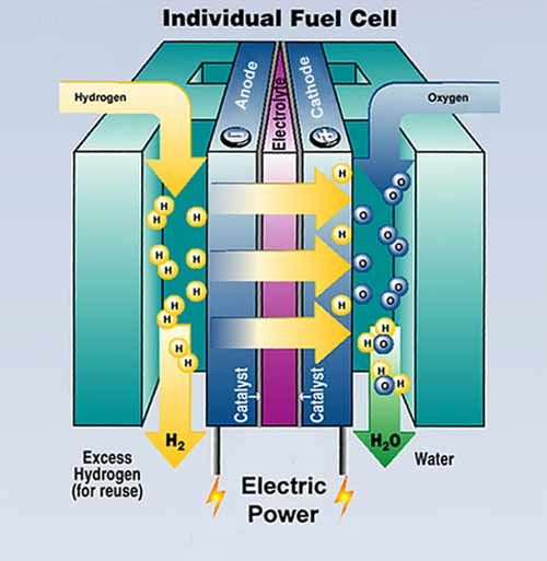
August 17, 2009              A REVIEW OF ENERGY STORAGE TECHNOLOGIES

Table of Contents
Section          Title                                                                                                                                 Page
                 Abstract ................................................................................................................................... i
                 Table of Contents .................................................................................................................... ii
                 List of Figures ......................................................................................................................... iv
                 List of Tables .......................................................................................................................... iv
                 Nomenclature ........................................................................................................................ vi
                 Acronyms and Abbreviations .................................................................................................vii

1                Introduction............................................................................................................................ 1
    1.1               Energy Storage for Ireland .......................................................................................................... 1

2                Parameters of an Energy Storage Device ................................................................................. 3
    2.1               Battery/Flow Battery Only .......................................................................................................... 3

3                Energy Storage Applications .................................................................................................... 3
    3.1               Load Management ..................................................................................................................... 3
    3.2               Spinning Reserve......................................................................................................................... 4
    3.3               Transmission and Distribution Stabilisation ............................................................................... 4
    3.4               Transmission Upgrade Deferral .................................................................................................. 4
    3.5               Peak Generation ......................................................................................................................... 4
    3.6               Renewable Energy Integration ................................................................................................... 4
    3.7               End‐Use Applications .................................................................................................................. 5
    3.8               Emergency Back‐Up .................................................................................................................... 5
    3.9               Demand Side Management (DSM) ............................................................................................. 5

4                Energy Storage Plant Components........................................................................................... 5
    4.1               Storage Medium ......................................................................................................................... 5
    4.2               Power Conversion System (PCS) ................................................................................................. 5
    4.3               Balance of Plant (BOP)................................................................................................................ 5

5                Energy Storage Techniques ..................................................................................................... 6
    5.1               Pumped‐Hydroelectric Energy Storage (PHES) ........................................................................... 6
       5.1.1            Applications .......................................................................................................................... 8
       5.1.2            Cost ....................................................................................................................................... 9
       5.1.3            Disadvantages ....................................................................................................................... 9
       5.1.4            Future ................................................................................................................................... 9

    5.2               Underground Pumped‐Hydroelectric Energy Storage (UPHES) ................................................ 10
       5.2.1            Applications ........................................................................................................................ 10
       5.2.2            Cost ..................................................................................................................................... 10
       5.2.3            Disadvantages ..................................................................................................................... 11
       5.2.4            Future ................................................................................................................................. 11

    5.3               Compressed Air Energy Storage (CAES) .................................................................................... 11
       5.3.1            Applications ........................................................................................................................ 12

          ii   Table of Contents | University of Limerick
A REVIEW OF ENERGY STORAGE TECHNOLOGIES August 17, 2009

      5.3.2              Cost ..................................................................................................................................... 12
      5.3.3              Disadvantages ..................................................................................................................... 12
      5.3.4              Future ................................................................................................................................. 13

    5.4             Battery Energy Storage (BES) ................................................................................................... 13
       5.4.1           Lead‐Acid (LA) battery ........................................................................................................ 13
       5.4.2           Nickel‐Cadmium (NiCd) battery .......................................................................................... 15
       5.4.3           Sodium‐Sulphur (NaS) Battery ............................................................................................ 17

    5.5             Flow Battery Energy Storage (FBES) ......................................................................................... 18
       5.5.1           Vanadium Redox (VR) Flow Battery .................................................................................... 18
       5.5.2           Polysulphide Bromide (PSB) Flow Battery .......................................................................... 20
       5.5.3           Zinc Bromine (ZnBr) Flow Battery ....................................................................................... 21

    5.6             Flywheel Energy Storage (FES).................................................................................................. 22
       5.6.1           Applications ........................................................................................................................ 23
       5.6.2           Cost ..................................................................................................................................... 23
       5.6.3           Disadvantages ..................................................................................................................... 23
       5.6.4           Future ................................................................................................................................. 24

    5.7             Supercapacitor Energy Storage (SCES) ..................................................................................... 24
       5.7.1           Applications ........................................................................................................................ 25
       5.7.2           Cost ..................................................................................................................................... 25
       5.7.3           Disadvantages ..................................................................................................................... 25
       5.7.4           Future ................................................................................................................................. 25

    5.8             Superconducting Magnetic Energy Storage (SMES) ................................................................. 25
       5.8.1           Applications ........................................................................................................................ 26
       5.8.2           Cost ..................................................................................................................................... 27
       5.8.3           Disadvantages ..................................................................................................................... 27
       5.8.4           Future ................................................................................................................................. 27

    5.9             Hydrogen Energy Storage (HESS).............................................................................................. 27
       5.9.1           Create Hydrogen ................................................................................................................. 27
       5.9.2           Store Hydrogen ................................................................................................................... 28
       5.9.3           Use Hydrogen ..................................................................................................................... 29
       5.9.4           Disadvantages ..................................................................................................................... 32
       5.9.5           Future of HESS .................................................................................................................... 32

    5.10            Thermal Energy Storage (TES) .................................................................................................. 32
       5.10.1          Air‐Conditioning Thermal Energy Storage (ACTES) ............................................................. 33
       5.10.2          Thermal Energy Storage System (TESS) .............................................................................. 33

    5.11            Electric Vehicles (EVs) ............................................................................................................... 35
       5.11.1           Applications ........................................................................................................................ 35
       5.11.2           Cost ..................................................................................................................................... 36
       5.11.3           Disadvantages ..................................................................................................................... 36
       5.11.4           Future ................................................................................................................................. 36

6               Comparison of Energy Storage Technologies ......................................................................... 37
    6.1             Large power and energy capacities .......................................................................................... 37
    6.2             Medium power and energy capacities ..................................................................................... 38
    6.3             Large power or storage capacities ........................................................................................... 38
    6.4             Overall comparison of energy storage technologies ................................................................ 38

                                                                                   University of Limerick | Table of Contents                           iii
August 17, 2009               A REVIEW OF ENERGY STORAGE TECHNOLOGIES

    6.5                    Energy storage systems ............................................................................................................ 43

7                     Conclusions........................................................................................................................... 44

8                     References ............................................................................................................................ 45

List of Figures
Figure                      Description                                                                                                                                    Page
Figure 1‐1: Wind production and interconnection trading for Denmark in December 2006 [4] ........................... 2
Figure 5‐1: Pumped‐Hydroelectric Energy Storage Layout [7] ............................................................................... 7
Figure 5‐2: Pumped‐Hydroelectric Storage facility using seawater [8] .................................................................. 8
Figure 5‐3: Output from a Pumped‐Hydroelectric Storage facility [7] ................................................................... 9
Figure 5‐4: Proposed Underground Pumped Hydroelectric Storage facility layout [9] ........................................ 10
Figure 5‐5: Compressed Air Energy Storage facility [12] ...................................................................................... 11
Figure 5‐6: Lead‐Acid Battery [17] ........................................................................................................................ 14
Figure 5‐7: Nickel‐Cadmium Battery [18] ............................................................................................................. 16
Figure 5‐8: Sodium‐Sulphur Battery [5] ................................................................................................................ 17
Figure 5‐9: 6 MW, 8 h NaS energy storage facility in Tokyo, Japan [2] ................................................................ 18
Figure 5‐10: Vanadium Redox Flow Battery [22] .................................................................................................. 19
Figure 5‐11: Polysulphide Bromide Flow Battery [5]. ........................................................................................... 20
Figure 5‐12: Zinc‐Bromine Battery [24] ................................................................................................................ 21
Figure 5‐13: Flywheel Energy Storage device [25]................................................................................................ 22
Figure 5‐14: Supercapacitor Energy Storage device [26]...................................................................................... 24
Figure 5‐15: Superconducting Magnetic Energy Storage device [2]..................................................................... 26
Figure 5‐16: Energy Density vs. Pressure for hydrogen gas [2] ............................................................................ 29
Figure 5‐17: Fuel Cell [31] ..................................................................................................................................... 30
Figure 5‐18: Air‐Conditioning Thermal Energy Storage setup [5] ......................................................................... 33
Figure 5‐19: Thermal energy storage system during (a) a low‐wind scenario and (b) a high‐wind scenario ....... 34
Figure 5‐20: Schematic of electric vehicles and electric power grid .................................................................... 35
Figure 5‐21: Cost of Battery Electric and conventional vehicles for a lifetime of 105,000 km (25% urban driving)
.............................................................................................................................................................................. 36
Figure 6‐1: Discharge Time vs. Power Ratings for each storage technology [37]................................................. 39
Figure 6‐2: Weight Energy Density vs. Volume Energy Density for each technology [37] ................................... 39
Figure 6‐3: Efficiency& Lifetime at 80% DoD for each technology [37]................................................................ 39
Figure 6‐4: Capital Cost for each technology [37] ................................................................................................ 40
Figure 6‐5: Cost per cycle for each technology [37] ............................................................................................. 40

List of Tables
Table                  Description                                                                                                                                    Page
                                                                                                                         th
Table 1‐1: Network Capacity for Ireland and Northern Ireland (Correct as of 18 January 2008) ........................ 2
Table 1‐2: Grid interconnection in and out of Denmark ........................................................................................ 2
Table 5‐1 ............................................................................................................................................................... 15
Table 5‐2: Fuel Cell types [1] ................................................................................................................................ 31
Table 6‐1: Characteristics of storage technologies [2] ......................................................................................... 41
Table 6‐2: Cost Characteristics of storage technologies [2] ................................................................................. 42
Table 6‐3: Technical suitability of storage technologies to different applications [2].......................................... 43

          iv      List of Figures | University of Limerick
A REVIEW OF ENERGY STORAGE TECHNOLOGIES August 17, 2009

                               University of Limerick | List of Tables   v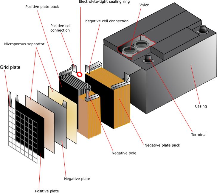
August 17, 2009      A REVIEW OF ENERGY STORAGE TECHNOLOGIES

Nomenclature
Symbol                        Description                                         Unit

A                             Area of parallel plates on capacitor                m2

C                             Capacitance                                         F

ECAP                          Energy stored in capacitor                          J

ECOIL                         Energy stored in coil (of SMES device)              J

EKINETIC                      Total kinetic energy in flywheel                    J

F                              Force                                              N (kgm/s2)

I                             Current                                             A

L                             Inductance of coil (in SMES device)                 H

PC                            Power Capacity                                      W (J/s)

SC                            Storage Capacity                                    Wh

T                             Temperature in Kelvin / degrees Celsius             K / °C

V                             Voltage                                             V

d                             Distance between parallel plated on capacitor       m

t                              Time                                               h, s

mf                            Mass of flywheel                                    kg

g                             Acceleration due to gravity                         m/s2

vCIRCULAR                     Circular velocity of flywheel                       m/s

ε0                            Permittivity of free space                          F/m

εr                            Relative permittivity/dielectric constant           F/m

ρ                             Density                                             kg/m3

σ                             Specific strength of flywheel material              Nm/kg

           vi   Nomenclature | University of Limerick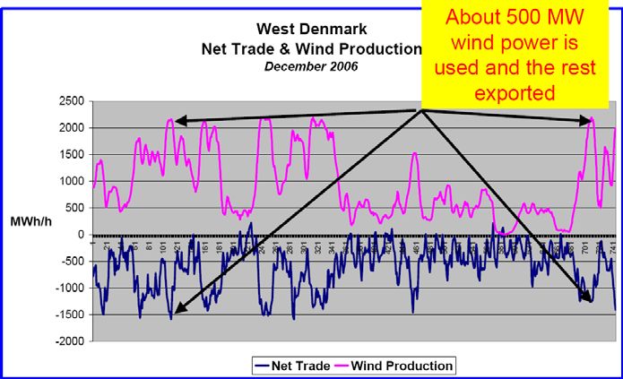
A REVIEW OF ENERGY STORAGE TECHNOLOGIES August 17, 2009

Acronyms and Abbreviations
Symbol           Description

AC               Alternating Current

ACTES            Air‐Conditioning Thermal Energy Storage

ATS              Aquifer Thermal Storage

BES              Battery Energy Storage

BOP              Balance of Plant

CAES             Compressed Air Energy Storage

DC               Direct Current

DoD              Depth of Discharge

DOE              Department of Energy (US)

DTS              Duct Thermal Storage

DSM              Demand Side Management

DSO              Distribution System Operator

EU               European Union

FBES             Flow Battery Energy Storage

FC               Fuel Cell

FES              Flywheel Energy Storage

GW               Gigawatt

GWh              Gigawatt‐hour

HESS             Hydrogen Energy Storage System

ICE              Internal Combustion Engine

kW               kilowatt

kWh              kilowatt‐hour

LA               Lead‐Acid

MJ               Mega joule (1 MJ = 0.28 kWh)

MW               Megawatt

MWh              Megawatt‐hour

NaS              Sodium Sulphur

                                       University of Limerick | Acronyms and Abbreviations   vii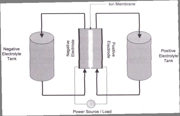
August 17, 2009    A REVIEW OF ENERGY STORAGE TECHNOLOGIES

NiCd                        Nickel Cadmium

Symbol                      Description

PCS                         Power Conversion System

PHES                        Pumped‐Hydroelectric Energy Storage

PSB                         Polysulphide Bromide

SCES                        Supercapacitor Energy Storage

SMES                        Superconducting Magnetic Energy Storage

T&D                         Transmission and Distribution

TES                         Thermal Energy Storage

TESS                        Thermal Energy Storage System

TSO                         Transmission System Operator

UK                          United Kingdom

UPS                         Uninterruptable Power Supply

US                          United States (of America)

VR                          Vanadium Redox

VRLA                        Valve‐Regulated Lead Acid

ZnBr                        Zinc Bromine

       viii   Acronyms and Abbreviations | University of Limerick
A REVIEW OF ENERGY STORAGE TECHNOLOGIES August 17, 2009
1 Introduction
Energy storage is a well established concept yet still relatively unexplored. Storage systems such as pumped‐
hydroelectric energy storage (PHES) have been in use since 1929 [1] primarily to level the daily load on the
network between night and day. As the electricity sector is undergoing a lot of change, energy storage is
starting to become a realistic option for [2]:
1. Restructuring the electricity market
2. Integrating renewable resources
3. Improving power quality
4. Aiding shift towards distributed energy
5. Helping network operate under more stringent environmental requirements
Energy storage can optimise the existing generation and transmission infrastructures whilst also preventing
expensive upgrades. Power fluctuations from renewable resources will prevent their large‐scale penetration
into the network. However energy storage devices can manage these irregularities and thus aid the
amalgamation of renewable technologies. In relation to conventional power production energy storage
devices can improve overall power quality and reliability, which is becoming more important for modern
commercial applications. Finally, energy storage devices can reduce emissions by aiding the transition to
newer, cleaner technologies such as renewable resources and the hydrogen economy. Therefore, Kyoto
obligations can be met (and penalties avoided).
A number of obstacles have hampered the commercialisation of energy storage devices including:
1. Lack of experience – a number of demonstration projects will be required to increase customer’s
confidence
2. Inconclusive benefits – consumers do not understand what exactly are the benefits of energy storage
in terms of savings and also power quality
3. High capital costs – this is clearly an issue when the first two disadvantages are considered
4. Who should pay for energy storage? Developers view storage as ‘grid infrastructure’ whereas the
Transmission System Operator (TSO) views it as part of the renewable energy plant.
However, as renewable resources and power quality become increasingly important, costs and concerns
regarding energy storage technologies are expected to decline.
This report was carried out to identify the numerous different types of energy storage devices currently
available. The parameters used to describe an energy storage device and the applications they fulfil are
explored first. This is followed by an analysis of each energy storage technology currently available indicating
there:
1. Operation and the advantages
2. Applications
3. Cost
4. Disadvantages
5. Future
Finally, a brief comparison of the various technologies is provided.
1.1 Energy Storage for Ireland
In order to reduce greenhouse gases, Ireland’s primary objective is to produce at least 33% of its electricity
from renewable resources by 2020. Currently, Ireland’s wind capacity has just reached 1000 MW,
approximately 13% of the total Irish network capacity, see Table 1‐1. However, previous reports had indicated
that grid stability can be affected once wind capacity passes 800 MW [3]. As a result, Ireland will need to
address the effects of grid intermittency in the immediate future.
University of Limerick | Introduction 1August 17, 2009 A REVIEW OF ENERGY STORAGE TECHNOLOGIES
Table 1‐1: Network Capacity for Ireland and Northern Ireland (Correct as of 18th January 2008)
Item Republic of Ireland Northern Ireland All‐Island
(MW) (MW) (MW)
Total Conventional Capacity (MW) 6245 1968 8213
Total Wind Capacity (MW) 1000♦ 182* 1182♦
Total 7245 2150 9395
♦
Numbers have been rounded for convenience
*Will increase to 408 MW by August 2009
The concept of having energy storage for an electric grid provides all the benefits of conventional generation
such as, enhanced grid stability, optimised transmission infrastructure, high power quality, excellent
renewable energy penetration and increased wind farm capacity. However, energy storage technologies
produce no carbon emissions and do not rely on imported fossil fuels. As a result, energy storage is a very
attractive option for increasing wind penetration onto the electric grid when it is needed.
However, currently Ireland’s solution to the grid problems associated with the intermittency of wind
generation is grid interconnection. EirGrid is in the process of constructing a 500 MW interconnector to Wales
that will allow for importing and exporting of electricity to and from Great Britain. Effectively, Great Britain will
be our ‘storage’ device: excess electricity can be sold when the wind is blowing and electricity can be imported
when it is not. A similar approach to improve grid stability was carried out in Denmark who installed large
interconnectors to neighbouring Germany, Norway and Sweden, see Table 1‐2.
Table 1‐2: Grid interconnection in and out of Denmark
Country Interconnection From Denmark (MW) Interconnection To Denmark (MW)
Germany 1200 800
Norway 950 1000
Sweden 610 580
Total 2760 2380
However, Denmark discovered that they were only using approximately 500 MW of their wind generation at
any time, see Figure 1‐1. The rest was being exported to Germany, Norway and Sweden.
Figure 1‐1: Wind production and interconnection trading for Denmark in December 2006 [4]
Although this makes it possible for Denmark to implement large quantities of wind generation, Denmark is not
only exporting wind power but also its benefits. Firstly, Denmark exports its wind power cheaper than it buys
power back. When excess wind power is available, Denmark needs to get rid of it, so Norway and Sweden
close their hydro generating facilities and buy cheaper wind power from Denmark. When wind production is
low, Norway and Sweden turn back on their hydro generators, which have now stored large amounts of
2 Introduction | University of LimerickA REVIEW OF ENERGY STORAGE TECHNOLOGIES August 17, 2009
energy, and sell power back to Denmark at a higher rate. By using Great Britain as a power sink/source to
accommodate wind power, Ireland too could face similar financial losses whilst exporting wind power.
Also, Germany uses the wind power generated in Denmark to reduce its own CO2 emissions. Although
Denmark is generating green power it is not profiting in terms of CO2 reductions. Consequently, if
interconnection is continued to be used in Ireland to integrate wind power onto the grid, Ireland’s green
power could be used to reduce the CO2 emissions of Great Britain rather than Ireland.
By using energy storage technologies instead of interconnection, Ireland can develop an independent, stable
and green electric grid.
2 Parameters of an Energy Storage Device
• Power Capacity: is the maximum instantaneous output that an energy storage device can provide,
usually measured in kilowatts (kW) or megawatts (MW).
• Energy Storage Capacity: is the amount of electrical energy the device can store usually measured in
kilowatt‐hours (kWh) or megawatt‐hours (MWh).
• Efficiency: indicates the quantity of electricity which can be recovered as a percentage of the
electricity used to charge the device.
• Response Time: is the length of time it takes the storage device to start releasing power.
• Round‐Trip Efficiency: indicates the quantity of electricity which can be recovered as a percentage of
the electricity used to charge and discharge the device.
2.1 Battery/Flow Battery Only
• Charge‐to‐Discharge Ratio: is the ratio of the time it takes to charge the device relative to the time it
takes to discharge the device i.e. if a device takes 5 times longer to charge than to discharge, it has a
charge‐to‐discharge ratio of 5:1.
• Depth of Discharge (DoD): is the percentage of the battery capacity that is discharged during a cycle.
• Memory Effect: If certain batteries are never fully discharged they ‘remember’ this and lose some of
their capacity.
3 Energy Storage Applications
Energy storage devices can accommodate a number of network requirements. These are [2]:
1. Load management
2. Spinning reserve
3. Transmission and distribution stabilisation
4. Transmission upgrade deferral
5. Peak generation
6. Renewable energy integration
7. End‐use applications
8. Emergency back‐up
9. Demand Side Management (DSM)
3.1 Load Management
There are two different aspects to load management:
1. Load levelling: using off‐peak power to charge the energy storage device and subsequently allowing it
to discharge during peak demand. As a result, the overall power production requirements becomes
flatter and thus cheaper baseload power production can be increased.
University of Limerick | Parameters of an Energy Storage Device 3August 17, 2009 A REVIEW OF ENERGY STORAGE TECHNOLOGIES
2. Load following: energy storage device acts as a sink when power required falls below production
levels and acts as a source when power required is above production levels.
Energy devices required for load management must be in the 1 MW to 100+ MW range as well as possessing
fast response characteristics.
3.2 Spinning Reserve
Once again spinning reserve is classified under two categories:
1. Fast response spinning reserve: power capacity that is kept in the state of ‘hot‐stand‐by’. As a result it
is capable of responding to network abnormalities quickly.
2. Conventional spinning reserve: power capacity that requires a slower response.
Energy storage devices used for spinning reserve usually require power ratings of 10 MW to 400 MW and are
required between 20 to 50 times per year.
3.3 Transmission and Distribution Stabilisation
Energy storage devices are required to stabilise the system after a fault occurs on the network by absorbing or
delivering power to generators when needed to keep them turning at the same speed. These faults induce
phase angle, voltage and frequency irregularities that are corrected by the storage device. Consequently, fast
response and very high power ratings (1 MW to 10 MW) are essential.
3.4 Transmission Upgrade Deferral
Transmission line upgrades are usually separated by decades and must be built to accommodate likely load
and generating expansions. Consequently, energy storage devices are used instead of upgrading the
transmission line until such time that it becomes economical to do so. Typically, transmission lines must be
built to handle the maximum load required and hence it is only partially loaded for the majority of each day.
Therefore, by installing a storage device, the power across the transmission line can maintained a constant
even during periods of low demand. Then when demand increases, the storage device is discharge preventing
the need for extra capacity on the transmission line to supply the required power. Therefore, upgrades in
transmission line capacities can be avoided. Storage devices for this application must have a power capacity of
kW to several hundreds of megawatts and a storage capacity of 1 to 3 hours. Currently the most common
alternative is portable generators; with diesel and fossil fuel power generators as long term solutions and
biodiesel generators as a short term solution.
3.5 Peak Generation
Energy storage devices can be charged during off‐peak hours and then used to provide electricity when it is the
most expensive, during short peak production periods.
3.6 Renewable Energy Integration
In order to aid the integration of renewable resources, energy storage could be used to:
1. Match the output from renewable resources to the load required
2. Store renewable energy during off‐peak time periods for use during peak hours
3. Act as ‘renewable back‐up’ by storing enough electricity when it is available to supply electricity when
it isn’t available
4. Smooth output fluctuations from a renewable resource
A storage system used with renewable technology must have a power capacity of 10 kW to 100 MW, have fast
response times (less than a second), excellent cycling characteristics and a good lifespan (100 to 1,000 cycles
per year).
4 Energy Storage Applications | University of LimerickA REVIEW OF ENERGY STORAGE TECHNOLOGIES August 17, 2009
3.7 EndUse Applications
The most common end‐use application is power quality which primarily consists of voltage and frequency
control. Transit and end‐use ride‐through are applications requiring short power durations and fast response
times, in order to level fluctuations, prevent voltage irregularities and provide frequency regulation. This is
primarily used on sensitive processing equipment.
3.8 Emergency BackUp
This is a type of UPS except the units must have longer energy storage capacities. The energy storage device
must be able to provide power while generation is cut altogether. Power ratings of 1 MW for durations up to
one day are most common.
3.9 Demand Side Management (DSM)
DSM involves actions that encourage end‐users to modify their level and pattern of energy usage. Energy
storage can be used to provide a suitable sink or source in order to facilitate the integration of DSM.
Conversely, DSM can be used to reduce the amount of energy storage capacity required in order to improve
the network. A report will be carried out investigating the possibilities relating to DSM by CPI.
4 Energy Storage Plant Components
Before discussing the technologies, a brief explanation of the components required to have an energy storage
device are discussed. Every energy storage facility is comprised of three primary components:
1. Storage Medium
2. Power Conversion System (PCS)
3. Balance of Plant (BOP)
4.1 Storage Medium
The storage medium is the ‘energy reservoir’ that retains the potential energy within a storage device. It
ranges from mechanical (Pumped‐Hydroelectric Energy Storage), chemical (Battery Energy Storage) and
electrical (Superconducting Magnetic Energy Storage) potential energy.
4.2 Power Conversion System (PCS)
It is necessary to convert from alternating current (AC) to direct current (DC) and vice versa, for all storage
devices except mechanical storage devices e.g. Pumped‐Hydroelectric and Compressed Air energy storage [5].
Consequently, a PCS is required that acts as a rectifier while the energy device is charged (AC to DC) and as an
inverter when the device is discharged (DC to AC). The PCS also conditions the power during conversion to
ensure that no damage is done to the storage device.
The customization of the PCS for individual storage systems has been identified as one of the primary sources
of improvement for energy storage facilities, as each storage device operates differently during charging,
standing and discharging [5]. The PCS usually costs from 33% to 50% of the entire storage facility.
Development of PCSs has been slow due to the limited growth in distributed energy resources e.g. small scale
power generation technologies ranging from 3 to 10,000 kW [6].
4.3 Balance of Plant (BOP)
These are all the devices that:
• Are used to house the equipment
• Control the environment of the storage facility
• Provide the electrical connection between the PCS and the power grid
University of Limerick | Energy Storage Plant Components 5August 17, 2009 A REVIEW OF ENERGY STORAGE TECHNOLOGIES
It is the most variable cost component within an energy storage device due to the various requirements for
each facility. The BOP “typically includes electrical interconnections, surge protection devices, a support rack
for the storage medium, the facility shelter and environmental control systems” [5].
“The balance‐of‐plant includes structural and mechanical equipment such as protective enclosure,
heating/ventilation/air conditioning (HVAC), and maintenance/auxiliary devices. Other BOP features include
the foundation, structure (if needed), electrical protection and safety equipment, metering equipment, data
monitoring equipment, and communications and control equipment. Other cost such as the facility site,
permits, project management and training may also be considered here” [2].
5 Energy Storage Techniques
Energy storage devices by their nature are typically suitable for a very particular set of applications. This is
primarily due to the potential power and storage capacities that can be obtained from the various devices.
Therefore, in order to provide a fair comparison between the various energy storage technologies, they have
been grouped together based on the size of power and storage capacity that can be obtained. Four categories
have been created: devices large power (>50 MW) and storage (>100 MWh) capacities; devices with medium
power (1‐50 MW) and storage capacities (5‐100 MWh); devices with medium power or storage capacities but
not both; and finally, a section on energy storage systems. These are energy storage technologies that will be
discussed along with their corresponding categories:
1. PHES
2. UPHES Large Power and Storage Capacities
3. CAES
4. BES
Medium Power and Storage Capacities
5. FBES
6. FES
7. SCES Large Power or Storage Capacities
8. SMES
9. HESS
10. TESS Energy Storage Systems
11. EVs
PHES, UPHES and CAES will be discussed together as they all have the potential for large power and storage
capacities; BES and FBES will be discussed together as they have the potential for medium power and storage
capacities, while FES, SCES, and SMES will be grouped together as they all have either medium‐scale power or
storage capacities. Finally HESS, TESS, and EVs will be discussed together as these are energy storage systems.
Before commencing it is worth noting which category each technology falls into. Only the technologies
common by category will be compared against each other after they have been analysed. HESS, TESS and EVs
have unique characteristics as these are energy systems i.e. it requires a number of different technologies
which can be controlled differently. As energy‐systems transform from a fossil‐fuel production based on
centralised production, to a renewable energy‐system, based on intermittent decentralised‐production, it is
imperative that system flexibility is maximised. An ideal option to achieve this is by integrating the three
primary sectors within any energy system: the electricity, heat and transport sectors. HESS, TESS and EV’s
provide unique opportunities to integrate these three sectors and hence increase the renewable‐energy
penetrations feasible. As a result it is difficult to compare HESS, TESS and EV’s to the other energy storage
technologies directly as energy storage is only part of the system they are composed of.
5.1 PumpedHydroelectric Energy Storage (PHES)
Pumped hydroelectric energy storage is the most mature and largest storage technique available. It consists of
two large reservoirs located at different elevations and a number of pump/turbine units (see Figure 5‐1).
6 Energy Storage Techniques | University of LimerickA REVIEW OF ENERGY STORAGE TECHNOLOGIES August 17, 2009
During off‐peak electrical demand, water is pumped from the lower reservoir to the higher reservoir where it
is stored until it is needed. Once required (i.e. during peak electrical production) the water in the upper
reservoir is released through the turbines, which are connected to generators that produce electricity.
Therefore, during production a PHES facility operates similarly to a conventional hydroelectric system.
Figure 5‐1: Pumped‐Hydroelectric Energy Storage Layout [7]
The efficiency of modern pumped storage facilities is in the region of 70% ‐ 85%. However, variable speed
machines are now being used to improve this. The efficiency is limited by the efficiency of the pump/turbine
unit used in the facilities [2].
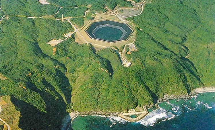
Until recently, PHES units have always used fresh water as the storage medium. However, in 1999 a PHES
facility using seawater as the storage medium was constructed [8], see Figure 5‐2; corrosion was prevented by
using paint and cathodic protection. A typical PHES facility has 300 m of hydraulic head (the vertical distance
between the upper and lower reservoir). The power capacity (kW) is a function of the flow rate and the
hydraulic head, whilst the energy stored (kWh) is a function of the reservoir volume and hydraulic head. To
calculate the mass power output of a PHES facility, the following relationship can be used [9]:
PC = ρgQHη (1)
Where:
PC = power capacity in Watts (W)
ρ = mass density of water in kg/m3
g = acceleration due to gravity in m/s2
Q = discharge through the turbines in m3/s
H = effective head in m
n = efficiency
And to evaluate the storage capacity of the PHES the following must be used [10]:
University of Limerick | Energy Storage Techniques 7August 17, 2009 A REVIEW OF ENERGY STORAGE TECHNOLOGIES
ρgHVη
SC = (2)
3.6 x10 9
Where:
SC = storage capacity in megawatt‐hours (MWh)
V = volume of water that is drained and filled each day in m3
ρ = mass density of water in kg/m3
g = acceleration due to gravity in m/s2
H = effective head in m
n = efficiency
It is evident that the power and storage capacities are both dependent on the head and the volume of the
reservoirs. However, facilities should be designed with the greatest hydraulic head possible rather than largest
upper reservoir possible. It is much cheaper to construct a facility with a large hydraulic head and small
reservoirs, than to construct a facility of equal capacity with a small hydraulic head and large reservoirs
because:
1. Less material needs to be removed to create the reservoirs required
2. Smaller piping is necessary, hence, smaller boreholes during drilling
3. The turbine is physically smaller
Currently, there is over 90 GW in more than 240 PHES facilities in the world – roughly 3% of the world’s global
generating capacity. Each individual facility can store from 30 MW to 4,000 MW (15 GWh) of electrical energy
[2].
Figure 5‐2: Pumped‐Hydroelectric Storage facility using seawater [8]
5.1.1 Applications
As well as large storage capacities, PHES also has a fast reaction time, hence identifying load‐levelling as an
ideal application, see Figure 5‐3. Facilities can have a reaction time as short as 10 minutes or less from
8 Energy Storage Techniques | University of LimerickA REVIEW OF ENERGY STORAGE TECHNOLOGIES August 17, 2009
complete shutdown (or from full reversal of operation) to full power [5]. In addition, if kept on standby, full
power can even be reached within 10 to 30 seconds.
Figure 5‐3: Output from a Pumped‐Hydroelectric Storage facility [7]
Also, with the recent introduction of variable speed machines, PHES systems can now be used for frequency
regulation in both pumping and generation modes (this has always been available in generating mode). This
allows PHES units to absorb power in a more cost‐effective manner that not only makes the facility more
useful, but also improves the efficiency by approximately 3% [5] and the life of the facility. PHES can also be
used for peak generation and black starts due to its large power capacity and sufficient discharge time. Finally,
PHES provides a load for base‐load generating facilities during off‐peak production, hence, cycling these units
can be avoided which improves their lifetime as well as their efficiency.
5.1.2 Cost
Cost ranges from $600/kW [2] to upwards of $2,000/kW [5], depending on a number of factors such as size,
location and connection to the power grid.
5.1.3 Disadvantages
Due to the design requirements of a PHES facility, the ultimate drawback is its dependence on specific
geological formations that is; two large reservoirs with a sufficient amount of hydraulic head between them
must be located within close proximity to build a PHES system. However, as well as being rare these geological
formations normally exist in remote locations such as mountains, where construction is difficult and the power
grid is not present. Although large wind farm sites may provide a useful modern alternative.
Finally, in order to make PHES viable it must be constructed on a large scale. Although the cost per kWh of
storage is relatively economical in comparison to other techniques, this large scale necessity results in a very
high initial construction cost for the facility, therefore detracting investment in PHES e.g. Bath County storage
facility in the United States which has a power capacity of 2,100 MW cost $1.7 billion in 1985.
5.1.4 Future
Currently, a lot of work is being carried out to upgrade old PHES facilities with new equipment such as variable
speed devices which can increase capacity by 15% to 20%, and efficiency by 5% to 10%. This is much more
University of Limerick | Energy Storage Techniques 9August 17, 2009 A REVIEW OF ENERGY STORAGE TECHNOLOGIES
popular as energy storage capacity is being developed without the high initial construction costs. Prospects of
building new facilities are limited due to the “high development costs, long lead times and design limitations”
[5]. However, a new concept that is showing a lot of theoretical potential is Underground Pumped‐
Hydroelectric Energy Storage (UPHES).
5.2 Underground PumpedHydroelectric Energy Storage (UPHES)
An UPHES facility has the same operating principle as PHES system: two reservoirs with a large hydraulic head
between them. The only major difference between the two designs is the locations of their respective
reservoirs. In conventional PHES, suitable geological formations must be identified to build the facility, as
discussed earlier (see section 5.1). However, UPHES facilities have been designed with the upper reservoir at
ground level and the lower reservoir deep below the earth’s surface. The depth depends on the amount of
hydraulic head required for the specific application, see Figure 5‐4.
Figure 5‐4: Proposed Underground Pumped Hydroelectric Storage facility layout [9]
5.2.1 Applications
UPHES can provide the same services as PHES: load‐levelling, frequency regulation, and peak generation.
However, as UPHES does not need to be built at a suitable geological formation, it can be constructed
anywhere with an area large enough for the upper reservoir. Consequently, it can be placed in ideal locations
to function with wind farms, the power grid, specific areas of electrical irregularities etc. The flexibility of
UPHES makes it a more attractive option for energy storage than conventional PHES, but its technical
immaturity needs to be addressed.
5.2.2 Cost
The capital cost of UPHES is the deciding factor for its future. As it operates in the same way as PHES, it is a
very reliable and cost effective storage technique with low maintenance costs. However, depending on the
large capital costs involved, UPHES might not be a viable option as other technologies begin to develop larger
10 Energy Storage Techniques | University of LimerickA REVIEW OF ENERGY STORAGE TECHNOLOGIES August 17, 2009
storage capacities e.g. flow batteries. Currently, no costs have been identified for UPHES, primarily due to the
lack of facilities constructed. A number of possible cost‐saving ideas have been put forward such as using old
mines for the lower reservoir of the facility [9] and [11]. Also, if something valuable can be removed to make
the lower reservoir, it can be sold to make back some of the cost.
5.2.3 Disadvantages
UPHES incorporates the same disadvantages as PHES (large‐scale required, high capital costs etc), with one
major exception. As stated previously (see section 5.1), the most significant problem with PHES is its geological
dependence. As the lower reservoir is obtained by drilling into the ground and the upper reservoir is at ground
level, UPHES doesn’t have such stringent geological dependences. The major disadvantage for UPHES is its
commercial youth. To date there is very few, if any, UPHES facilities in operation. Therefore, it is very difficult
to analyse and to trust the performance of this technology.
5.2.4 Future
UPHES has a very bright future if cost‐effective excavation techniques can be identified for its construction. Its
relatively large‐scale storage capacities, combined with its location independence, provide a storage technique
with unique characteristics. However, as well as cost, a number of areas need to be investigated further in this
area such as its design, power and storage capacities and environmental impact to prove it is a viable option.
5.3 Compressed Air Energy Storage (CAES)
A CAES facility consists of a power train motor that drives a compressor (to compress the air into the cavern),
high pressure turbine (HPT), a low pressure turbine (LPT), and a generator, see Figure 5‐5.
Exhaust
Waste Heat
Air
Motor Compressor Recuperator HPT LPT Generator
Fuel (Natural Gas)
Compressed
Air
Salt Dome
Cavern
Figure 5‐5: Compressed Air Energy Storage facility [12]
In conventional Gas Turbines (GT), 66% of the gas used is required to compress the air at the time of
generation. Therefore, CAES pre‐compresses the air using off‐peak electrical power which is taken from the
grid to drive a motor (rather than using gas from the GT plant) and stores it in large storage reservoirs. When
the GT is producing electricity during peak hours, the compressed air is released from the storage facility and
University of Limerick | Energy Storage Techniques 11August 17, 2009 A REVIEW OF ENERGY STORAGE TECHNOLOGIES
used in the GT cycle. As a result, instead of using expensive gas to compress the air, cheaper off‐peak base load
electricity is used.
However, when the air is released from the cavern it must be mixed with a small amount of gas before
entering the turbine. If there was no gas added, the temperature and pressure of the air would be
problematic. If the pressure using air alone was high enough to achieve a significant power output, the
temperature of the air would be far too low for the materials and connections to tolerate [1]. The amount of
gas required is so small that a GT working simultaneously with CAES can produce three times more electricity
than a GT operating on its own, using the same amount of natural gas.
The reservoir can be man‐made but this is expensive so CAES locations are usually decided by identifying
natural geological formations that suit these facilities. These include salt‐caverns, hard‐rock caverns, depleted
gas fields or an aquifer. Salt‐caverns can be designed to suit specific requirements. Fresh water is pumped into
the cavern and left until the salt dissolves and saturates the fresh water. The water is then returned to the
surface and the process is repeated until the required volume cavern is created. This process is expensive and
can take up to two years. Hard‐rock caverns are even more expensive, usually 60% higher than salt‐caverns.
Finally, aquifers cannot store the air at high pressures and therefore have a relatively lower energy capacity.
CAES uses both electrical energy and natural gas so its efficiency is difficult to quantify. It is estimated that the
efficiency of the cycle based on the compression and expansion cycles is in the region of 68% [13] to 75% [5].
Typical plant capacities for CAES are in the region of 50 MW – 300 MW. The life of these facilities is proving to
be far longer than existing gas turbines and the charge/discharge ratio is dependent on the size of the
compressor used, as well as the size and pressure of the reservoir.
5.3.1 Applications
CAES is the only very large scale storage technique other than PHES. CAES has a fast reaction time with plants
usually able to go from 0% to 100% in less than ten minutes, 10% to 100% in approximately four minutes and
from 50% to 100% in less than 15 seconds [2]. As a result, it is ideal for acting as a large sink for bulk energy
supply and demand and also, it is able to undertake frequent start‐ups and shutdowns. Furthermore,
traditional GT suffer a 10% efficiency reduction from a 5°C rise in ambient temperatures due a reduction in the
air density. CAES use compressed air so they do not suffer from this effect. Also, traditional gas turbines suffer
from excessive heat when operating on partial load, while CAES facilities do not. These flexibilities mean that
CAES can be used for ancillary services such as frequency regulation, load following, and voltage control [5]. As
a result, CAES has become a serious contender in the wind power energy storage market. A number of
possibilities are being considered such as integrating a CAES facility with a number of wind farms within the
same region. The excess off‐peak power from these wind farms could be used to compress air for a CAES
facility. Iowa Association of Municipal Utilities is currently planning a project of this nature [14].
5.3.2 Cost
The cost of CAES facilities are $425/kW [2] to $450/kW [5]. Maintenance is estimated between $3/kWh [15]
and $10/kWh [16]. Costs are largely dependent on the reservoir construction. Overall, CAES facilities expect to
have costs similar to or greater than conventional GT facilities. However, the energy cost is much lower for
CAES systems.
5.3.3 Disadvantages
The major disadvantage of CAES facilities is their dependence on geographical location. It is difficult to identify
underground reservoirs where a power plant can be constructed, is close to the electric grid, is able to retain
compressed air and is large enough for the specific application. As a result, capital costs are generally very high
for CAES systems. Also, CAES still uses a fossil fuel (gas) to generate electricity. Consequently, the emissions
and safety regulations are similar to conventional gas turbines. Finally, only two CAES facilities currently exist,
meaning it is still a technology of potential not experience.
12 Energy Storage Techniques | University of LimerickA REVIEW OF ENERGY STORAGE TECHNOLOGIES August 17, 2009
5.3.4 Future
Reservoir developments are expected in the near future due to the increased use of natural gas storage
facilities. The US and Europe are more likely to investigate this technology further as they possess acceptable
geology for an underground reservoir (specifically salt domes). Due to the limited operational experience,
CAES has been considered too risky by many utilities [16].
A number of CAES storage facilities have been planned for the future including:
• 25 MW CAES research facility with aquifer reservoir in Italy
• 3 x 100 MW CAES plant in Israel
• Norton Energy Storage LLC in America is planning a CAES with a limestone mine acting as the
reservoir. The first of four phases is expected to produce between 200 MW and 480 MW at a cost of
$50 to $480 million. The final plant output is planned to be 2,500 MW.
Finally, proposals have also been put forward for a number of similar technologies such as micro CAES and
thermal and compressed air storage (TACAS). However, both are in the early stages of development and their
future impact is not decisive. Although Joe Pinkerton, CEO of Active Power, declared that TACAS “is the first
true minute‐for‐minute alternative to batteries for UPS industry” [5].
5.4 Battery Energy Storage (BES)
There are three important types of large‐scale BES. These are:
1. Lead‐Acid (LA)
2. Nickel‐Cadmium (NiCd)
3. Sodium‐Sulphur (NaS)
These operate in the same way as conventional batteries, except on a large scale i.e. two electrodes are
immersed in an electrolyte, which allows a chemical reaction to take place so current can be produced when
required.
5.4.1 LeadAcid (LA) battery
This is the most common energy storage device in use at present. Its success is due to its maturity (research
has been ongoing for an estimated 140 years), relatively low cost, long lifespan, fast response, and low self‐
discharge rate. These batteries are can be used for both short‐term applications (seconds) and long‐term
applications (up to 8 hours).
There are two types of lead‐acid (LA) batteries; flooded lead‐acid (FLA) and valve‐regulated lead‐acid (VRLA).
FLA batteries are made up of two electrodes that are constructed using lead plates which are immersed in a
mixture of water (65%) and sulphuric acid (35%), see Figure 5‐6. VRLA batteries have the same operating
principle as FLA batteries, but they are sealed with a pressure‐regulating valve. This eliminates air from
entering the cells and also prevents venting of the hydrogen. VRLA batteries have lower maintenance costs,
weigh less and occupy less space. However, these advantages are coupled with higher initial costs and shorter
lifetime.
University of Limerick | Energy Storage Techniques 13You can also read