2018 ACC/HRS/NASCI/SCAI/SCCT - Heart Rhythm Society
←
→
Page content transcription
If your browser does not render page correctly, please read the page content below
JOURNAL OF THE AMERICAN COLLEGE OF CARDIOLOGY                                                                                    VOL.   -, NO. -, 2018
                    ª 2018 BY THE AMERICAN COLLEGE OF CARDIOLOGY FOUNDATION
                    PUBLISHED BY ELSEVIER

                    EXPERT CONSENSUS DOCUMENT

                   2018 ACC/HRS/NASCI/SCAI/SCCT
                   Expert Consensus Document on
                   Optimal Use of Ionizing Radiation
                   in Cardiovascular Imaging—
                   Best Practices for Safety and
                   Effectiveness, Part 2: Radiological
                   Equipment Operation, Dose-Sparing
                   Methodologies, Patient and Medical
                   Personnel Protection
                    A Report of the American College of Cardiology Task Force on Expert Consensus Decision Pathways

                    Developed in Collaboration With Mended Hearts

Writing             John W. Hirshfeld, JR, MD, FACC, FSCAI, Chair                                  Gilbert L. Raff, MD, FACCk
Committee           Victor A. Ferrari, MD, FACC, Co-Chair                                          Geoffrey D. Rubin, MD, MBA, FNASCI{
Members                                                                                            Donnette Smith#
                    Frank M. Bengel, MD*                                                           Arthur E. Stillman, MD, PHD, FNASCI
                    Lisa Bergersen, MD, MPH, FACC                                                  Suma A. Thomas, MD, MBA, FACC
                    Charles E. Chambers, MD, FACC, MSCAIy                                          Thomas T. Tsai, MD, MSC, FACC
                    Andrew J. Einstein, MD, PHD, FACC                                              Louis K. Wagner, PHD
                    Mark J. Eisenberg, MD, MPH, FACC                                               L. Samuel Wann, MD, MACC
                    Mark A. Fogel, MD, FACC
                    Thomas C. Gerber, MD, FACC
                                                                                                   *Society of Nuclear Medicine and Molecular Imaging Representative.
                    David E. Haines, MD, FACCz
                                                                                                   ySociety for Cardiovascular Angiography and Interventions
                    Warren K. Laskey, MD, MPH, FACC, FSCAI                                         Representative. zHeart Rhythm Society Representative. xAmerican Society
                    Marian C. Limacher, MD, FACC                                                   of Nuclear Cardiology Representative. kSociety for Cardiovascular
                    Kenneth J. Nichols, PHDx                                                       Computed Tomography Representative. {North American Society for
                                                                                                   Cardiovascular Imaging Representative. #Mended Hearts Representative.
                    Daniel A. Pryma, MD

                        This document was approved by the American College of Cardiology Clinical Policy Approval Committee in November 2017 and the approval bodies of
                    the Heart Rhythm Society, North American Society for Cardiovascular Imaging, Society for Cardiovascular Angiography and Interventions, and Society
                    of Cardiovascular Computed Tomography in January 2018.
                        The American College of Cardiology requests that this document be cited as follows: Hirshfeld JW Jr, Ferrari VA, Bengel FM, Bergersen L, Chambers CE,
                    Einstein AJ, Eisenberg MJ, Fogel MA, Gerber TC, Haines DE, Laskey WK, Limacher MC, Nichols KJ, Pryma DA, Raff GL, Rubin GD, Smith D, Stillman AE, Thomas
                    SA, Tsai TT, Wagner LK, Wann LS. 2018 ACC/HRS/NASCI/SCAI/SCCT expert consensus document on optimal use of ionizing radiation in cardiovascular
                    imaging—best practices for safety and effectiveness, part 2: radiologic equipment operation, dose-sparing methodologies, patient and medical personnel
                    protection: a report of the American College of Cardiology Task Force on Clinical Expert Consensus Documents. J Am Coll Cardiol 2018;71:XXXX–XXXX.
                        Copies: This document is available on the World Wide Web site of the American College of Cardiology (www.acc.org). For copies of this document,
                    please contact Elsevier Reprint Department via fax (212) 633-3820 or e-mail (reprints@elsevier.com).
                        Permissions: Multiple copies, modification, alteration, enhancement, and/or distribution of this document are not permitted without the express
                    permission of the American College of Cardiology. Requests may be completed online via the Elsevier site (http://www.elsevier.com/about/our-
                    business/policies/copyright/permissions).

ISSN 0735-1097/$36.00                                                                                                            https://doi.org/10.1016/j.jacc.2018.02.018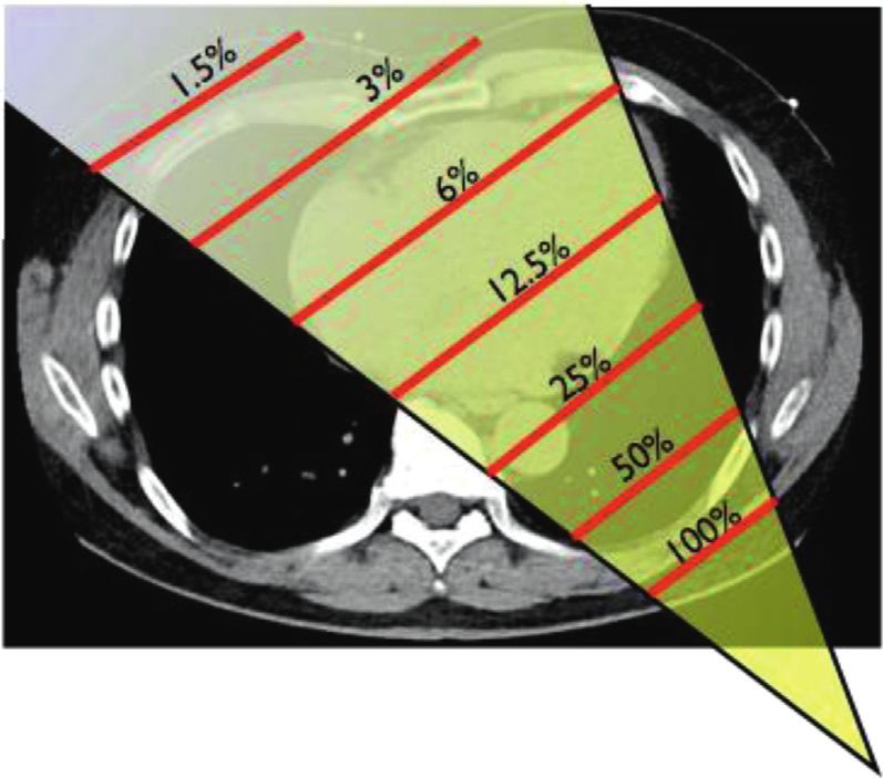
2   Hirshfeld Jr. et al.                                                                                                                          JACC VOL.     -, NO. -, 2018
    Radiation Safety ECD, Part 2                                                                                                                                  -, 2018:-–-

    ACC Task Force             James L. Januzzi, JR, MD, FACC                                            Pamela Bowe Morris, MD, FACC
    on Expert                  Luis C. Afonso, MBBS, FACC                                                Robert N. Piana, MD, FACC
    Consensus                  Brendan Everett, MD, FACC                                                 Karol E. Watson, MD, FACC
    Decision                   Adrian F. Hernandez, MD, MHS, FACC                                        Barbara S. Wiggins, PHARMD, AACC
    Pathways**                 William Hucker, MD, PHD
                               Hani Jneid, MD, FACC
                                                                                                         **Formerly named ACC Task Force on Clinical Expert
                               Dharam Kumbhani, MD, SM, FACC
                                                                                                         Consensus Documents.
                               Joseph Edward Marine, MD, FACC

    TABLE OF CONTENTS

    ABSTRACT . . . . . . . . . . . . . . . . . . . . . . . . . . . . . . . . . . . . . . -      4. MODALITY-SPECIFIC DOSE REDUCTION
                                                                                                 STRATEGIES . . . . . . . . . . . . . . . . . . . . . . . . . . . . . . . . . . -
    PREAMBLE . . . . . . . . . . . . . . . . . . . . . . . . . . . . . . . . . . . . . . -
                                                                                                  4.1. General Principles . . . . . . . . . . . . . . . . . . . . . . . . . .       -

                                                                                                        4.1.1. Case Selection . . . . . . . . . . . . . . . . . . . . . . . . .     -
     1. INTRODUCTION . . . . . . . . . . . . . . . . . . . . . . . . . . . . . . . -
                                                                                                        4.1.2. Dose-Determining Variables . . . . . . . . . . . . .                 -

    2. PURPOSE . . . . . . . . . . . . . . . . . . . . . . . . . . . . . . . . . . . . . -              4.1.3. Image Quality Issues . . . . . . . . . . . . . . . . . . .           -

                                                                                                  4.2. X-Ray Fluoroscopy . . . . . . . . . . . . . . . . . . . . . . . . . .        -
    3. MODALITY-SPECIFIC RADIATION                                                                      4.2.1. General Principles . . . . . . . . . . . . . . . . . . . . .         -
       EXPOSURE DELIVERY . . . . . . . . . . . . . . . . . . . . . . . . . . -                          4.2.2. Digital X-Ray System Operating Modes . . . .                         -

        3.1. General Principles . . . . . . . . . . . . . . . . . . . . . . . . . . .       -           4.2.3. X-Ray System Calibration, Operation,
              3.1.1. Characteristics of Medical                                                                and Dose . . . . . . . . . . . . . . . . . . . . . . . . . . . . .   -

                     Diagnostic Radiation . . . . . . . . . . . . . . . . . . . .           -           4.2.4. Determinants of Total Dose for an
              3.1.2. Tools Used to Estimate Absorbed Dose . . . . .                         -
                                                                                                               Exposure . . . . . . . . . . . . . . . . . . . . . . . . . . . . .   -

                                                                                                        4.2.5. Procedures and Practices to Minimize
        3.2. X-Ray Fluoroscopy . . . . . . . . . . . . . . . . . . . . . . . . . .          -                  Patient and Personnel Exposure . . . . . . . . . .                   -

               3.2.1. X-Ray Fluoroscopy Subject and                                                     4.2.6. Pregnant Occupationally Exposed
                      Operator Exposure Issues . . . . . . . . . . . . . . .                -                  Workers . . . . . . . . . . . . . . . . . . . . . . . . . . . . .    -

              3.2.2. Basics of Operation of an X-Ray                                                    4.2.7. Alternative Imaging Techniques . . . . . . . . . .                   -
                     Cinefluorographic Unit . . . . . . . . . . . . . . . . . .              -
                                                                                                        4.2.8. Summary Checklist for Dose-Sparing in
              3.2.3. Measures and Determinants of                                                              X-Ray Fluoroscopy . . . . . . . . . . . . . . . . . . . .            -

                     Subject and Operator Exposure . . . . . . . . . .                      -
                                                                                                  4.3. X-Ray Computed Tomography . . . . . . . . . . . . . . . .                    -
              3.2.4. Measures and Determinants of Physician                                             4.3.1. X-Ray CT General Principles . . . . . . . . . . . . .                -
                     Operator and Healthcare Worker
                                                                                                        4.3.2. Equipment Quality and Calibration . . . . . . .                      -
                     Occupational Exposure . . . . . . . . . . . . . . . . .                -
                                                                                                        4.3.3. Variables That Affect Patient Dose
        3.3. X-Ray CT . . . . . . . . . . . . . . . . . . . . . . . . . . . . . . . . . .   -                  for X-Ray CT . . . . . . . . . . . . . . . . . . . . . . . . .       -

               3.3.1. X-Ray CT Subject and Operator                                                     4.3.4. Summary Checklist of Dose-Sparing
                      Dose Issues . . . . . . . . . . . . . . . . . . . . . . . . . . .     -                  Practices for X-Ray CT . . . . . . . . . . . . . . . . . .           -

              3.3.2. Basics of Operation of an                                                   4.4. Nuclear Cardiology Techniques . . . . . . . . . . . . . . . .                 -
                     X-Ray CT Unit . . . . . . . . . . . . . . . . . . . . . . . .          -
                                                                                                        4.4.1. Nuclear Cardiology General Principles . . . . .                      -
              3.3.3. X-Ray CT Measures of                                                               4.4.2. Nuclear Cardiology Equipment Quality,
                     Subject Exposure . . . . . . . . . . . . . . . . . . . . . .           -                  Calibration, and Maintenance . . . . . . . . . . . .                 -

              3.3.4. X-Ray CT Measures of Effective Dose . . . . .                          -           4.4.3. Nuclear Cardiology Spatial Resolution and
                                                                                                               Image Detector Dose . . . . . . . . . . . . . . . . . . .            -
       3.4. Patient and Medical Personnel Exposure in
                                                                                                        4.4.4. Procedures and Practices to Minimize
            Nuclear Cardiology . . . . . . . . . . . . . . . . . . . . . . . . . .          -
                                                                                                               Patient Exposure . . . . . . . . . . . . . . . . . . . . . .         -
              3.4.1. Patient Exposure in Nuclear Cardiology . . . .                         -
                                                                                                        4.4.5. Procedures and Practices to Protect
              3.4.2. Personnel Exposure in Nuclear                                                             Occupationally Exposed Healthcare
                     Cardiology . . . . . . . . . . . . . . . . . . . . . . . . . . . .     -                  Workers in Nuclear Cardiology Facilities . . .                       -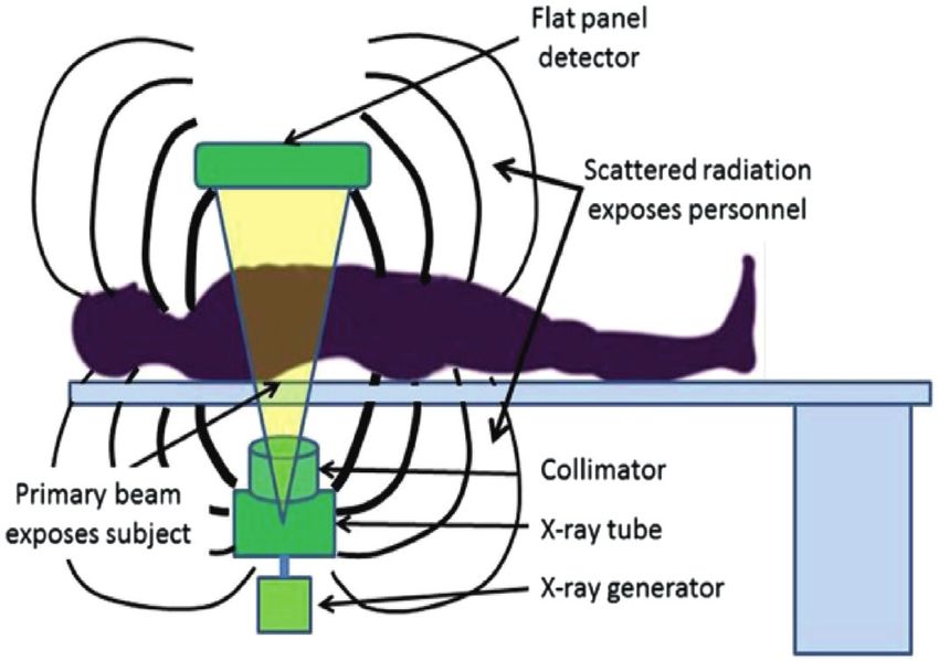
JACC VOL.     -, NO. -, 2018                                                                                                                      Hirshfeld Jr. et al.   3
-, 2018:-–-                                                                                                                             Radiation Safety ECD, Part 2

          4.4.6. Summary Checklist of Dose-Sparing                                            ABSTRACT
                 Practices for Nuclear Cardiology . . . . . . . . .                       -

   4.5. Summary of Dose Minimization Strategies in                                            The stimulus to create this document was the recogni-
        X-Ray Fluoroscopy, X-Ray CT, and                                                      tion that ionizing radiation-guided cardiovascular pro-
        Cardiovascular Nuclear Scintigraphy . . . . . . . . . . .                         -   cedures are being performed with increasing frequency,
                                                                                              leading to greater patient radiation exposure and,

5. SUMMARY, CONCLUSIONS, AND
                                                                                              potentially, to greater exposure to clinical personnel.

   RECOMMENDATIONS . . . . . . . . . . . . . . . . . . . . . . . . . . -
                                                                                              While the clinical benefit of these procedures is sub-
                                                                                              stantial, there is concern about the implications of
    5.1. The Issue . . . . . . . . . . . . . . . . . . . . . . . . . . . . . . . . . .    -   medical radiation exposure. ACC leadership concluded
          5.1.1. Patient Participation in Clinical                                            that it is important to provide practitioners with an
                 Imaging Decisions . . . . . . . . . . . . . . . . . . . . . .            -
                                                                                              educational resource that assembles and interprets the
                                                                                              current radiation knowledge base relevant to cardiovas-
   5.2. Clinical Value of Radiation-Based Imaging Studies
        and Radiation-Guided Therapeutic Procedures . . .                                 -   cular procedures. By applying this knowledge base, car-
                                                                                              diovascular    practitioners    will    be     able      to    select
   5.3. Individual Patient Risk and Population Impact                                         procedures optimally, and minimize radiation exposure
        (Including Occupationally Exposed Workers) . . . . .                              -
                                                                                              to patients and to clinical personnel.
   5.4. The ALARA Principle . . . . . . . . . . . . . . . . . . . . . . . .               -     “Optimal Use of Ionizing Radiation in Cardiovascular
                                                                                              Imaging - Best Practices for Safety and Effectiveness” is a
   5.5. The Potential to Minimize Exposure to
                                                                                              comprehensive overview of ionizing radiation use in
        Patients and Personnel . . . . . . . . . . . . . . . . . . . . . . .              -
                                                                                              cardiovascular procedures and is published online. To
          5.5.1. Imaging Modality Choice . . . . . . . . . . . . . . . .                  -
                                                                                              provide the most value to our members, we divided the
          5.5.2. Procedure Conduct Choice . . . . . . . . . . . . . .                     -
                                                                                              print version of this document into 2 focused parts.
          5.5.3. Protecting Occupationally Exposed                                            “Part I: Radiation Physics and Radiation Biology” ad-
                 Workers . . . . . . . . . . . . . . . . . . . . . . . . . . . . . .      -
                                                                                              dresses radiation physics, dosimetry and detrimental
   5.6. Physician Responsibilities to Minimize                                                biologic effects. “Part II: Radiologic Equipment Operation,
        Patient Exposure . . . . . . . . . . . . . . . . . . . . . . . . . . .            -   Dose-Sparing      Methodologies,       Patient     and        Medical
          5.6.1. Case Selection . . . . . . . . . . . . . . . . . . . . . . . . .         -   Personnel Protection” covers the basics of operation and
          5.6.2. Procedure Conduct . . . . . . . . . . . . . . . . . . . . .              -   radiation delivery for the 3 cardiovascular imaging mo-
          5.6.3. Facility Management . . . . . . . . . . . . . . . . . . .                -   dalities (x-ray fluoroscopy, x-ray computed tomography,
                                                                                              and nuclear scintigraphy). For each modality, it includes
   5.7. Patient Radiation Dose Tracking . . . . . . . . . . . . . . .                     -   the determinants of radiation exposure and techniques to
   5.8. Need for Quality Assurance and Training . . . . . . . .                           -   minimize exposure to both patients and to medical
                                                                                              personnel.
REFERENCES . . . . . . . . . . . . . . . . . . . . . . . . . . . . . . . . . . . -

APPENDIX A
                                                                                              PREAMBLE
   Author Relationships With Industry and Other Entities
   (Relevant) . . . . . . . . . . . . . . . . . . . . . . . . . . . . . . . . . . . . .   -
                                                                                              This document has been developed as an Expert
                                                                                              Consensus Document by the American College of Cardi-
APPENDIX B
                                                                                              ology (ACC) in collaboration with the American Society of
   Peer Reviewer Relationships With Industry and                                              Nuclear Cardiology, Heart Rhythm Society, Mended
   Other Entities (Relevant) . . . . . . . . . . . . . . . . . . . . . . . . .            -
                                                                                              Hearts,   North    American    Society     for    Cardiovascular
                                                                                              Imaging, Society for Cardiovascular Angiography and
APPENDIX C
                                                                                              Interventions, Society for Cardiovascular Computed To-
   Abbreviations . . . . . . . . . . . . . . . . . . . . . . . . . . . . . . . . . .      -   mography, and Society of Nuclear Medicine and Molecu-
                                                                                              lar Imaging. Expert Consensus Documents are intended to
APPENDIX D                                                                                    inform practitioners, payers, and other interested parties
   Operator Education, Quality Assurance,                                                     of the opinion of ACC and document cosponsors con-
   Radiation Dose Monitoring, and Tracking . . . . . . . . . . .                          -   cerning   evolving    areas    of   clinical     practice      and/or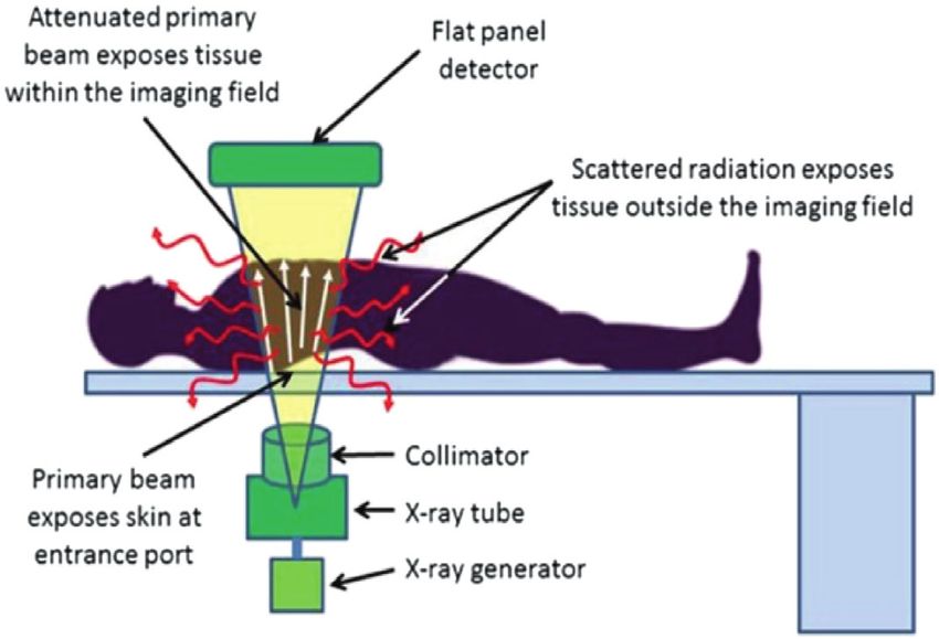
4   Hirshfeld Jr. et al.                                                                                           JACC VOL.   -, NO. -, 2018
    Radiation Safety ECD, Part 2                                                                                                -, 2018:-–-

    technologies that are widely available or new to the                   1. INTRODUCTION
    practice community. Topics chosen for coverage by expert
    consensus documents are so designed because the evi-                   1.1. Document Development Process and Methodology
    dence base, the experience with technology, and/or clin-               1.1.1. Writing Committee Organization
    ical    practice       are     not   considered   sufficiently   well
                                                                           The writing committee consisted of a broad range of
    developed to be evaluated by the formal ACC/American
                                                                           members representing 9 societies and the following areas
    Heart Association practice guidelines process. Often the
                                                                           of expertise: interventional cardiology, general cardiol-
    topic is the subject of considerable ongoing investigation.
                                                                           ogy, pediatric cardiology, nuclear cardiology, nuclear
    Thus, the reader should view the Expert Consensus
                                                                           medicine, electrophysiology, cardiac computed tomogra-
    Document as the best attempt of the ACC and document
                                                                           phy (CT), cardiovascular imaging, and the consumer pa-
    cosponsors to inform and guide clinical practice in
                                                                           tient perspective. Both a radiation safety biologist and
    areas where rigorous evidence may not yet be available
                                                                           physicist were included on the writing committee.
    or evidence to date is not widely applied to clinical
                                                                             This writing committee met the College’s disclosure
    practice.
                                                                           requirements for RWI as described in the Preamble.
       To avoid actual, potential, or perceived conflicts of
    interest that may arise as a result of industry relation-              1.1.2. Document Development and Approval
    ships or personal interests among the writing committee,
                                                                           The Writing Committee convened by conference call and e-
    all members of the writing committee, as well as peer
                                                                           mail to finalize the document outline, develop the initial
    reviewers of the document, are asked to disclose all cur-
                                                                           draft, revise the draft per committee feedback, and ulti-
    rent healthcare-related relationships, including those
                                                                           mately approve the document for external peer review.
    existing 12 months before initiation of the writing effort.
                                                                           All participating organizations participated in peer review,
    The ACC Task Force on Expert Consensus Decision
                                                                           resulting in 21 individual reviewers submitting 299
    Pathways (formerly the ACC Task Force on Clinical Expert
                                                                           comments. Comments were reviewed and addressed by
    Consensus Documents) reviews these disclosures to
                                                                           the writing committee. A member of the ACC Task Force on
    determine which companies make products (on market or
                                                                           Expert Consensus Decision Pathways served as lead
    in development) that pertain to the document under
                                                                           reviewer to ensure that all comments were addressed
    development. Based on this information, a writing com-
                                                                           adequately. Both the writing committee and the task force
    mittee is formed to include a majority of members with
                                                                           approved the final document to be sent to the ACC Clinical
    no relevant relationships with industry (RWI), led by a
                                                                           Policy Approval Committee. This committee reviewed
    chair with no relevant RWI. Authors with relevant RWI are
                                                                           the document, including all peer review comments and
    not permitted to draft or vote on text or recommenda-
                                                                           writing committee responses, and approved the document
    tions pertaining to their RWI. RWI is reviewed on all
                                                                           in November 2017. The Heart Rhythm Society, North
    conference calls and updated as changes occur. Author
                                                                           American Society for Cardiovascular Imaging, Society for
    and peer reviewer RWI pertinent to this document are
                                                                           Cardiovascular Angiography and Interventions, and Soci-
    disclosed in Appendixes A and B, respectively. Addi-
                                                                           ety of Cardiovascular Computed Tomography endorsed the
    tionally, to ensure complete transparency, authors’
                                                                           document in January 2018. This document is considered
    comprehensive disclosure information— including RWI
                                                                           current until the Task Force on Expert Consensus Decision
    not pertinent to this document—is available online
                                                                           Pathways revises or withdraws it from publication.
    (see Online Appendix). Disclosure information for the
    ACC Task Force on Clinical Expert Consensus Documents                  2. PURPOSE
    is also available online, as is the ACC disclosure policy for
    document development.                                                  This print-published document is part 2 of an abbreviated
       The work of the writing committee was supported                     version of a larger, more comprehensive document that is
    exclusively by the ACC without commercial support.                     published concurrently online. The online version con-
    Writing committee members volunteered their time to                    tains additional technical detail for readers who wish to
    this effort. Conference calls of the writing committee                 understand a topic in greater depth. The online published
    were confidential and attended only by committee                        document, in addition to covering the topics in the 2
    members and ACC staff.                                                 print-published documents in greater depth, also covers
                                                                           additional topics not covered in the print-published doc-
                                           James L. Januzzi, MD, FACC      uments including 1) dose reduction strategies; 2) operator
                            Chair, ACC Task Force on Clinical Expert       education and certification; 3) quality assurance; and
                                                 Consensus Documents       4) patient radiation tracking.
JACC VOL. -, NO. -, 2018 Hirshfeld Jr. et al. 5
-, 2018:-–- Radiation Safety ECD, Part 2
This document covers equipment operation for the 3 1% to 5% of the incident x-ray penetrates the subject
cardiovascular procedure classes that employ ionizing reaching the image detector to form the image.
radiation: x-ray fluoroscopy, x-ray CT, and radionuclide
scintigraphy. For the 3 modalities, it includes discussions 3.1.2. Tools Used to Estimate Absorbed Dose
of radiation delivery and strategies to minimize dose both Estimates of absorbed dose for x-ray fluoroscopy and
to patients and to occupationally exposed medical x-ray CT are based on models developed by exposing
personnel. In addition, it covers issues of quality assur- instrumented phantoms to incident x-ray beams that
ance, radiation monitoring, and tracking. replicate the beams used in diagnostic imaging and
The document’s purpose is to provide a comprehensive measuring absorbed dose at different points within the
information source about ionizing radiation use in car- phantom. Estimating absorbed dose from radionuclides is
diovascular procedures. The writing group has assembled an entirely different discipline that is discussed in Section
this information to assist cardiovascular practitioners to 4.4 of “Part I: Radiation Physics and Radiation Biology”.
provide optimal cardiovascular care when employing
ionizing radiation-based procedures. The goal is to
3.2. X-Ray Fluoroscopy
enhance cardiovascular practitioners’ ability to select the
optimal imaging technique for a given clinical circum- 3.2.1. X-Ray Fluoroscopy Subject and Operator Exposure Issues
stance, balancing a technique’s risk and benefits, and to X-ray fluoroscopy differs from other ionizing radiation
apply that technique optimally to generate high-quality imaging techniques in that the beam entrance port is
diagnostic images of greatest clinical value and minimal relatively small. Consequently, the skin at the beam
radiation exposure. entrance port is the most intensely exposed tissue.
Subject skin doses can reach levels that cause skin tissue
reactions. X-ray photons are also scattered within the
3. MODALITY-SPECIFIC RADIATION
subject. These deliver dose to subject tissues outside of
EXPOSURE DELIVERY
the imaging field (Figure 1). Scattered photons that exit
the subject can expose nearby medical personnel
3.1. General Principles
(Figure 2). Consequently, assessment of the implications
3.1.1. Characteristics of Medical Diagnostic Radiation of subject exposure from x-ray fluoroscopy must
For all 3 imaging modalities (x-ray fluoroscopy, x-ray CT, consider entrance port skin dose, which is the dose
and nuclear scintigraphy), 95% to 99% of radiation energy received by internal structures within the imaging field
that enters or is released within the subject is either and by other internal structures outside of the imaging
absorbed or scattered within the subject. The remaining field.
F I G U R E 1 Diagrammatic Representation of an X-Ray Fluoroscopy System to Illustrate X-Ray Exposure Modality
The primary beam, collimated to a rectangular cross section, enters the patient, typically through the patient’s back. It is attenuated and scattered within the
imaging field. The primary beam exposes the subject within the imaging field. The scattered primary beam radiation can expose structures within the subject
that are remote from the imaging field.6 Hirshfeld Jr. et al. JACC VOL. -, NO. -, 2018
Radiation Safety ECD, Part 2 -, 2018:-–-
F I G U R E 2 Diagrammatic Representation of the Pattern of X-Ray Scatter From a Subject Undergoing X-Ray Fluoroscopy
Note that scattered x-ray emanates from the subject in all directions.
3.2.2. Basics of Operation of an X-Ray Cinefluorographic Unit to image formation. Layers of aluminum and copper in
An x-ray cinefluorographic unit generates controlled x- the x-ray tube exit port filter out these “undesirable”
rays in an x-ray tube that are collimated to regulate the photons.
size and shape of the beam. The beam passes through the
subject forming images that are detected by a flat panel 3.2.3. Measures and Determinants of Subject and
detector (Figure 1). The x-ray tube output (and accord- Operator Exposure
ingly the exposure to the subject) is modulated by feed-
There are 2 different x-ray fluoroscopic system parame-
back circuitry from the unit’s imaging chain to achieve an
ters (described in detail in Section 4.4.1 of Part 1) that
optimally exposed image.
characterize x-ray exposure and dose:
X-Ray Cinefluorographic Unit Operating Parameters
There are multiple imaging parameters that influence the 1) Cumulative air kerma at the interventional reference
x-ray exposure associated with an x-ray cinefluorographic point. Kerma is an acronym for “kinetic energy
examination. These are: released in material.”
2) Cumulative kerma-area product (KAP).
1. X-ray image detector dose per pulse. The dose for each
x-ray pulse (typically measured in nanogray [nGy])
that reaches the x-ray system detector. This parameter Cumulative Air Kerma at the
is set by the x-ray unit calibration. It determines image Interventional Reference Point
clarity and detail. A procedure’s cumulative air kerma at the interventional
2. X-ray unit framing (pulsing) rate. The number of pul- reference point is a more meaningful measure of subject
ses that the x-ray system generates per unit time. This exposure than the total fluoroscopic time, which does
is an operator-selectable parameter that generally not account for selected detector dose, subject density,
ranges between 4 and 30 pulses/s. It determines image cine acquisition time, or changes in frame rate and
temporal resolution. angulation.
3. Imaging field size. The area of the x-ray beam that X-ray exposure to the subject is not uniform. As an
impinges on the subject. x-ray beam passes through a subject, tissue absorption
4. X-ray beam filtration. An x-ray tube produces a attenuates it. Tissue closer to the beam entrance port
spectrum of x-ray photon energies. Photon receives a larger dose than deeper-lying tissue (Figure 3).
energiesJACC VOL. -, NO. -, 2018 Hirshfeld Jr. et al. 7
-, 2018:-–- Radiation Safety ECD, Part 2
3.2.4. Measures and Determinants of Physician Operator and
F I G U R E 3 Diagram Showing the Estimated Decreasing Intensity of
X-Ray Exposure With Depth Within the Subject
Healthcare Worker Occupational Exposure
Application of KAP in Cardiovascular X-Ray Fluoroscopy
to Estimates of Effective Dose to Medical Personnel
Medical personnel who conduct x-ray fluoroscopic pro-
cedures are exposed by scattered radiation (Figure 2). The
cumulative quantity of scattered radiation is directly
related to the procedure’s cumulative KAP.
The quantity of scattered radiation that reaches and
delivers dose to medical personnel is determined by:
1. The distance of the exposed medical personnel from
the x-ray source—scattered x-ray intensity decreases
proportionately to the square of the distance from the
source.
2. The effectiveness of shielding employed by the
exposed medical personnel.
Physician and Medical Personnel Exposure Monitoring
In this example, (right anterior oblique projection), the beam enters Estimates of radiation dose to exposed medical
the left side of the subject’s back. Beam intensity decreases with depth personnel are based on measurements made by personal
within the subject due to a combination of beam divergence with
radiation monitors (formerly known as “film badges”).
distance (inverse square law) and absorption within the subject. The
overall effect of these processes is to attenuate the beam intensity
The outside badge mounted at collar level outside
that exits the subject to 5% or less of the incident intensity. protective garments) measures the dose that reaches
unshielded structures of the head. A badge worn
underneath protective garments measures the dose that
tissue within the imaging area, but is not negligible
penetrates the protective apron reaching the subject.
(Figure 1).
These measure total exposure in mGy. The personal
Kerma-Area Product
radiation monitor readings are converted using an
KAP, the product of air kerma output and image field size,
algorithm to estimate effective dose to the subject
sometimes referred to as dose-area product, is commonly
in mSv (2–5). The details of these measurements and
used as a metric to estimate a subject’s total absorbed
calculations are included in the full version of this
dose. It incorporates both dose intensity and exposed
document published online.
tissue volume into a single measurement. KAP is also
directly related to the quantity of scattered radiation that Exposure Levels for Operating Physicians
leaves the subject’s body and, accordingly, to the Most studies of operating physician dosimetry find a
magnitude of exposure to nearby medical personnel range of 0.02 to 0.12 m Sv/Gy$cm 2 KAP for the procedure
(Figure 2). with typical values clustering about 0.1 mSv/Gy$cm 2 (6,7).
2
KAP is expressed in units of Gy$cm . It is calculated by (Note that the estimated patient exposure is 200 m Sv/
multiplying the beam air kerma by its cross-sectional Gy$cm 2, indicating that operator exposure is roughly
area. Some x-ray system manufacturers report KAP in 1/2,000 of patient exposure.) Applying these values, a
units of m Gy$m 2 (1 Gy$cm 2 ¼ 100 m Gy$m 2). It should also be “typical” combined coronary arteriogram and straight-
noted that air kerma and KAP represent cumulative doses forward coronary interventional procedure utilizing a
from an exposure, not exposure rates. cumulative KAP of 50 Gy$cm2 would deliver a 5-m Sv
Application of KAP in Cardiovascular X-Ray effective dose to the physician operator standing roughly
Fluoroscopy to Estimates of Effective Dose to Patients 1 m from the center of the primary beam while delivering
The most commonly used estimate of the relationship 10 mSv to the patient.
between KAP exposure to the thorax in Gy$cm 2 and Special considerations for occupationally exposed
effective dose in Sieverts (Sv) is 0.20 mSv/Gy$cm2 (1). By workers who are pregnant or may become pregnant are
this estimate, a combination coronary arteriography and discussed in Section 4.2 of this document and in greater
percutaneous coronary intervention that delivers a KAP detail in section 5.4.4 of “Part I: Radiation Physics and
exposure of 50 Gy$cm 2 would impart an effective dose to Radiation Biology” and in the longer, online-published
the subject of 10 mSv. version of this document.8 Hirshfeld Jr. et al. JACC VOL. -, NO. -, 2018
Radiation Safety ECD, Part 2 -, 2018:-–-
F I G U R E 4 Comparison of Retrospective ECG Gating With Prospective ECG Gating
With retrospective gating, the intensity-modulated x-ray beam is on for the entirety of the R-R intervals during imaging. With prospective gating, the x-ray
beam is on for about 26% of every other R-R interval. Reproduced with permission from Shuman et al. (8).
3.3. X-Ray CT Electrocardiographic gating, which can have a major
3.3.1. X-Ray CT Subject and Operator Dose Issues impact on dose, is important in cardiovascular imaging to
minimize motion artifact.
Although x-ray CT, like x-ray fluoroscopy, is an external
There are 2 types of gating (Figure 4):
beam exposure technique, unlike x-ray fluoroscopy the
incident beam is distributed circumferentially around the n Retrospective gating involves x-ray exposure contin-
subject. Consequently, x-ray CT subject skin doses should ually over the cardiac cycle. Because exposure occurs
never approach levels that could cause skin injury, and continuously, retrospective gating delivers greater
subject-harm issues should be confined to stochastic risk. exposure than prospective triggering.
The dose delivered by an x-ray CT examination is not n Prospective triggering involves synchronizing expo-
uniform, delivering greater dose to more superficial lo- sure to a selected portion of the cardiac cycle. The goal
cations compared with deeper locations closer to the of prospective triggering is for exposure to occur only
exposed volume center. when cardiac motion is minimal.
3.3.2. Basics of Operation of an X-Ray CT Unit 3.3.3. X-Ray CT Measures of Subject Exposure
The dose delivered by an x-ray CT examination can vary The dose delivered by an x-ray CT examination should be
substantially depending on patient characteristics and considered from 2 perspectives:
the settings of multiple scanner operating parameters.
n Dose Intensity: Dose per unit mass of tissue. This is a
Configurable CT technique parameters that can affect
measure of the intensity of the dose used to generate
dose include x-ray tube potential (measured in kV), x-ray
the images.
tube current (measured in milliamperes [mA]), scan pro-
n Volume of Tissue Exposed. The total dose delivered to
tocol (e.g., axial or helical), pitch, gating protocol, scan
a subject is the product of the dose intensity and the
rotation time, beam width, scan length, and beam
volume of tissue exposed.
filtration.
Image quality is affected by imaging parameter selec- Although CT dose metrics are derived from the mea-
tion. This selection involves a conscious balancing of surement of x-ray tube air kerma, in the CT lexicon, the
image quality and dose. Other parameter selections, such term “dose” is widely used.
as gating protocol, do not necessarily affect image quality CT Dose Index—A Measure of Dose Intensity
but do affect the amount of radiation used to acquire an Computed tomography dose index (CTDI) was first
image set. defined in 21 CFR 1020.33(c) as the average dose detectedJACC VOL. -, NO. -, 2018 Hirshfeld Jr. et al. 9
-, 2018:-–- Radiation Safety ECD, Part 2
over a 100-mm scan length from an imaging acquisition of phantoms for the determination of DLP. For that reason,
14 slices. It is a measure of dose intensity, that is, the dose when reporting CTDI or DLP in children, the phantom size
imparted by a unit scan length. used should always be specified. In addition, in children,
CTDI100 sensitivity to a stochastic event varies substantially with
CTDI 100 is a refinement of CTDI that standardizes all dose subject age. Consequently, in children, European guide-
index measurements to a scan length of 100 mm. lines for chest CT conversion factors (19), based on the 32-
Weighted CTDI 100 cm phantom, range from 0.013 mSv $ mGy 1 $ cm 1 (age 10
The CTDIw, or weighted CTDI 100, is an index developed to years) to 0.039 mSv $ mGy 1 $ cm 1 (age 0 years). Only 2
approximate the average radiation dose delivered to a studies using contemporary cardiac scanners have deter-
cross section of a subject’s body, allowing for dose vari- mined cardiac CT-specific conversion factors for children.
ation with depth. Normalized to the 32-cm phantom, conversion factors (20)
Volume CTDI range from 0.092 to 0.099 mSv $ mGy 1 $ cm 1 for age 1
CTDI vol is the weighted absorbed dose to air of a 1 cm year, 0.049 to 0.082 mSv $ mGy 1 $ cm 1 for age 5 years,
axial length of the examined subject located in the (19) and 0.049 mSv $ mGy 1 $ cm 1 for age 10 years.
middle section of a 100-mm length scan of an acrylic
cylinder for a specific CT technique. It accounts for both 3.4. Patient and Medical Personnel Exposure in
the exposure directly delivered to the 1-cm thick slice Nuclear Cardiology
and the exposure to that slice by scatter from adjacent 3.4.1. Patient Exposure in Nuclear Cardiology
imaged tissue.
Unlike x-ray imaging, which principally exposes the
CTDI vol Special Considerations for Exposure in Children
imaged structures, an injected radioactive tracer exposes
It is noteworthy that for identical techniques, smaller
the entire body. Organs receiving the highest radiation
subjects receive a higher dose than larger subjects. Esti-
dose may not be the imaged structures. The patient’s
mates of CTDI vol for body imaging made utilizing a 32-cm
behavior after study completion can alter the rate of
thick phantom underestimate the dose received by
radiopharmaceutical excretion, affecting the overall ra-
smaller individuals by a factor of 2.
diation dose.
Size-Specific Dose Estimate
Estimating the effective dose from a radiopharmaceu-
Size-specific dose estimate is a normalization of CTDIvol
tical exposure incorporates:
that takes into account subject size. Its incorporation into
practice is still to be determined. 1. Quantity of radioactivity administered.
Dose-Length Product—A Measure of the Total Dose 2. Radiopharmaceutical distribution within the subject.
Absorbed by the Subject 3. Kinetics of distribution to and elimination from each
Dose-length product (DLP) is the product of CTDI vol and organ.
the axial scan length. It is a measure of total dose to the 4. Radiosensitivity of each exposed organ.
subject and is analogous to KAP for x-ray fluoroscopy. 5. Physical half-life of the radionuclide and its emitted
Accordingly, for x-ray CT, DLP is the best predictor of photon or particle energy.
stochastic risk.
Medical internal radiation dose is a commonly used
framework for estimating the radiation dose from radio-
3.3.4. X-Ray CT Measures of Effective Dose
pharmaceuticals. The medical internal radiation dose
For CT imaging, European Commission–sponsored
method uses the radiopharmaceutical’s “effective” half-
guidelines from 2000 (9) and 2004 (10) have suggested a
life—the combination of radionuclide organ residence
simple approximation of the effective dose that can be
times and physical decay rates—to estimate the total dose
obtained by multiplying the DLP by a conversion factor k
1 1
(in mGy) received by each organ. These values are
(unit: mSv $ mGy $ cm ) that varies dependent on the
multiplied by the individual organ radiation sensitivities
radiation sensitivity of different body regions and patient
to yield the individual organ equivalent doses, which are
ages. There are specified conversion factors for CT of the
then summed to calculate the whole-body effective dose
head, neck, chest, abdomen, pelvis, and legs (11). The
for the subject in mSv.
most common conversion factor for adult chest CT is
Additional dose issues:
0.014 mSv $ mGy 1 $ cm1 (12), with values for children
being greater. For CT examinations confined to the car- 1. A renally excreted radiopharmaceutical will deliver a
diac region, estimated conversion factors are greater, with radiation dose to the bladder wall. If the subject voids
an average value of 0.026 mSv $ mGy 1 $ cm 1 (13–18). infrequently, the dose to the bladder will be higher.
X-Ray CT Measures of Effective Dose in Children 2. Radiopharmaceutical imaging studies, both positron
Pediatric CT dosimetry is complicated by the fact that imaging (positron emission tomography [PET]) and
scanners and studies have variably used 32- or 16-cm single-photon emission computed tomography10 Hirshfeld Jr. et al. JACC VOL. -, NO. -, 2018
Radiation Safety ECD, Part 2 -, 2018:-–-
(SPECT), which employ attenuation correction, utilize a is important always to seek to minimize patient radiation
hybrid radiation-based technique to estimate attenua- exposure (this is a particular consideration in younger
tion. This delivers an additional exposure. patients who have long natural life expectancies), it is
equally important to not withhold appropriate studies
3.4.2. Personnel Exposure in Nuclear Cardiology due to undue concern of the radiation-related risk.
Nuclear cardiology personnel receive exposure both from
4.1.2. Dose-Determining Variables
handling radiopharmaceutical doses and from their
The radiation dose delivered to patients and medical
proximity to radioactive patients. There are substantive
personnel (regardless of modality) is affected by 3 vari-
differences, compared with x-ray environments, in the
ables that are under the operator’s control. These are:
variables affecting personnel exposure:
1. Equipment quality and calibration
1. The photons emitted from the subject from radio-
2. Equipment operating protocols
pharmaceuticals are generally of higher energy than
3. Operator conduct
the x-rays emitted from fluoroscopy or CT devices.
Therefore, personal shielding devices such as lead As each of these variables influences the dose delivered
aprons or leaded glasses are less effective and, conse- to the patient (and also, potentially to operating medical
quently, are rarely used. Nuclear cardiology personnel personnel), each provides an opportunity to reduce dose.
rely on the principles of time and distance, minimizing
the time they spend in close proximity to either the 4.1.3. Image Quality Issues
dose syringe or the injected patient. Image quality is a major determinant of an examination’s
2. Unlike x-ray environments, the radiopharmaceutical is diagnostic accuracy. Inadequate image quality may cause
a continuous source of activity that can be excreted via either incorrect diagnoses or a need to repeat an exami-
body fluids or spread during administration. Thus, nation—requiring additional patient exposure. Conse-
subject blood and excreted body fluids are radioactive. quently, it is imperative that radiological equipment meet
An accident or error can cause a healthcare worker to current image quality standards, be maintained in prime
receive an exposure from contamination. working order, and are operated properly to produce
high-quality diagnostic images.
4. MODALITY-SPECIFIC DOSE REDUCTION Radiological image quality is strongly influenced by the
STRATEGIES detector dose—the quantity of radiation that reaches the
image detector. Overall image quality is determined by
4.1. General Principles spatial and temporal resolution, the signal-to-noise ratio,
Table 1 indicates core principles to follow for the use of the contrast-to-noise ratio, and presence of imaging arti-
medical ionizing radiation for diagnostic and therapeutic facts. Most tactics that increase either spatial resolution (by
procedures. improving signal-to-noise ratio and contrast-to-noise ra-
tio) or temporal resolution (by increasing framing rate) do
Core Principles for the Use of Medical Ionizing so at the cost of increased dose. The challenge is to optimize
TABLE 1 Radiation for Diagnostic and Therapeutic these properties by balancing the tradeoffs between dose
Procedures
and image quality. There are circumstances in which the
1. The examination should be conducted such that the dose received by the “best” image that the system can deliver is better than
patient and attendant medical personnel is the smallest necessary to yield
satisfactory diagnostic efficacy. needed for diagnosis. Consequently, operators can choose
2. Diagnostic and therapeutic efficacy should not be compromised in the interest
to accept a lower image quality, which is still sufficiently
of sparing radiation dose. diagnostic, to reduce patient (and operator) radiation dose.
3. If the study’s purpose can be achieved employing a modality that does not Spatial Resolution—Detector Input Dose, Pulse Width,
employ ionizing radiation, serious consideration should be given to the
and Nuclear Scan Acquisition
alternative modality.
Image signal-to-noise ratio is inversely proportional to
the square root of the detector dose. Low signal-to-noise
4.1.1. Case Selection ratio images have a “grainy” appearance because the
The most effective way to reduce patient radiation image is formed by a small number of x-ray photons. This
exposure is to perform a radiation-based procedure only grainy quality, termed “quantum mottle,” becomes
when it is the preferred choice among alternative mo- smoother as dose increases, improving the ability to
dalities that do not involve radiation exposure (e.g., stress perceive image detail.
echo or stress cardiac magnetic resonance). Appropriate Examples of the impact of detector dose on image noise
use criteria should be applied to select patients to un- for x-ray fluoroscopic imaging are presented in Figure 5.
dergo diagnostic and therapeutic procedures. Although it These are images of a line pair phantom acquired at differentJACC VOL. -, NO. -, 2018 Hirshfeld Jr. et al. 11 -, 2018:-–- Radiation Safety ECD, Part 2 F I G U R E 5 Images of a Line Pair Phantom Acquired in an X-Ray Fluoroscopic System at Different Detector Doses (as Labeled on the Individual Images) Note the progressive decrease in image noise and the ability to perceive image detail as the dose increases: 10 nGy/frame, an unacceptably low dose; 18 nGy/ frame, representative dose for low-dose fluoroscopy; 40 nGy/frame, representative dose for standard-dose fluoroscopy; 200 nGy/frame, representative dose for cine acquisition; 1,200 nGy/frame, representative dose for digital subtraction imaging. detector doses ranging from 10 to 1,200 nGy/frame. counts per unit time, and the image acquisition time, with As the number of photons reaching the detector increases, longer acquisition times acquiring a larger number of image noise decreases and the image becomes smoother. counts. Over a defined range, as image noise decreases, perceptible The cardiovascular system moves. This imposes image spatial resolution increases. For each imaging additional requirements on cardiovascular imaging sys- modality there is an upper limit of dose beyond which tems. Spatial resolution is also determined by x-ray further dose increase, although it may produce a smoother- pulse width. Images acquired with pulse durations >8 appearing image, does not yield greater image detail of ms will be degraded by motion unsharpness just as diagnostic importance. photographs of moving objects are blurred if acquired at Similarly, the image noise in x-ray CT images is deter- slower camera shutter speeds. Typical pulse durations mined in part by detector dose. Larger doses will yield are 2 to 8 ms. images with less noise and, within limits, greater spatial Temporal Resolution—Pulse Frequency resolution. For x-ray CT, the spatial resolution required to If an image series (such as an x-ray fluoroscopy cine assess myocardial contours, and, accordingly, the dose acquisition) is acquired at too slow of a frame rate, events needed to achieve it, is smaller than that required to im- that occur during time periods shorter than the framing age coronary arteries. rate will not be resolved and object motion will cause the For nuclear scan images, the number of gamma ray image to have a jerky quality. counts that are acquired to construct the image de- termines the image noise and, accordingly, its spatial 4.2. X-Ray Fluoroscopy resolution, which improves as the number of counts ac- Of the 3 imaging modalities, x-ray fluoroscopy has the quired increases. The number of counts acquired is greatest variability in dose per procedure and has the determined by the amount of radioactivity administered potential to deliver the largest dose to patients, operators, for the examination, which determines the number of and nearby medical personnel. Dose is substantially
12 Hirshfeld Jr. et al. JACC VOL. -, NO. -, 2018
Radiation Safety ECD, Part 2 -, 2018:-–-
affected by operator choices, behavior, equipment qual- catheter placement can be accomplished with fluoro-
ity, and calibration. scopic frame rates as slow as 4 frames/s. More complex
procedures such as coronary and structural interventions
4.2.1. General Principles require greater temporal resolution and employ frame
For an x-ray fluoroscopic examination, the total skin dose rates between 10 and 15 frames/s.
(in Gy) is determined by the sum of air kermas of all the Cine acquisition frame rates also vary with the purpose
frames (fluoroscopy and cine acquisition) in the exami- of the examination. For coronary arteriography, a frame
nation. The total effective dose is proportional to the sum rate of 10 to 15 frames/s is generally adequate. For adult
of the KAPs of all of the examination’s frames. ventriculography, 30 frames/s is preferred to achieve
more precise identification of end diastole and end sys-
4.2.2. Digital X-Ray System Operating Modes tole. In pediatric applications, framing rates as fast as 60
Digital x-ray imaging systems operate in 3 modes that frames/s are occasionally needed.
employ different detector doses to achieve different im-
age spatial resolution. 4.2.4. Determinants of Total Dose for an Exposure
Dose per Frame and Framing Rate
1. Fluoroscopy—the lowest-dose imaging protocol that
The optimal parameter settings for a fluoroscopic
yields images with the lowest spatial resolution.
examination or a cine acquisition run are determined by
Typical fluoroscopic detector doses range between 20
the patient’s particular circumstance’s and requirements
and 40 nGy/frame.
for spatial and temporal resolution. For fluoroscopy
2. Cine acquisition—an intermediate-dose imaging proto-
mode, current x-ray units typically provide tableside-
col intended to provide diagnostic quality images for
selectable fluoroscopy detector dose per frame levels
archiving and diagnostic interpretation. Cine acquisi-
that produce different degrees of image noise. They also
tion images have less image noise than fluoroscopic
provide tableside fluoroscopy and cine acquisition frame
images but should still have visible noise. Typical cine
rates ranging from 4 to 30 pulses/s. For cine acquisition
acquisition detector dose rates are 200 nGy/frame.
mode, the detector dose per pulse is set by the service
3. Digital subtraction—Digital subtraction algorithms are
engineer but the operator is able to select the frame
highly sensitive to image noise and require high doses
rate.
to function effectively. Consequently, digital subtrac-
X-Ray Imaging Field Size and System Positioning
tion algorithms per frame dose rates are the largest
Whereas the dose per pulse and the number of pulses
(typically 1,200 nGy/frame).
determine the total dose intensity (in mGy) delivered to
the patient, the product of the total dose and the imaging
4.2.3. X-Ray System Calibration, Operation, and Dose field size determines the total amount of radiation energy
The goals and purposes of an examination determine the (expressed as the KAP in Gy$cm 2) that the patient re-
optimal balance between radiation exposure and image ceives. In addition to the examination’s total number of
spatial and temporal resolution. For example, for x-ray pulses and the detector dose per pulse, the KAP is
fluoroscopy, the spatial and temporal resolution required affected by 2 additional parameters that are under the
for general catheter placement and manipulation is less operator’s control: the imaging field size selected and
than that required to perform cardiac interventional system positioning.
procedures. Current x-ray fluoroscopy systems are X-Ray Imaging Field Size
capable of imaging at multiple frame rates and can adjust Current x-ray systems link brightness stabilization
detector gain to utilize variable detector doses (21,22). detection to a collimator position that samples only the
These capabilities enable the operator to select an optimal detector area receiving the collimated x-ray beam. Conse-
imaging protocol for a particular situation. quently, the dose per pulse to the detector is not affected
Temporal Resolution Issues and Dose Tradeoffs by collimator position. However, the KAP is directly related
Because the cardiovascular system moves, x-ray fluoro- to the size of the imaged area. The consequence of this
graphic imaging requires short pulse durations to limit phenomenon is that, for a given detector zoom (magnifi-
image motion unsharpness (typically between 3 and 8 ms cation or input phosphor size) mode, smaller image area
for adults, as short as 2 ms for children). sizes deliver proportionately smaller KAPs. Thus, at a given
Fluoroscopic temporal resolution requirements vary detector zoom mode, reducing exposed field size by colli-
substantially depending on the examination’s purpose. In mation to the smallest size necessary minimizes the KAP
less demanding circumstances, the operator can decrease that the patient receives. This is not true for changing
dose by utilizing slower frame rates and lower doses detector zoom modes. Detector dose per pulse increases as
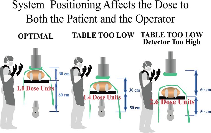
per frame without compromising effectiveness. General the zoom magnification increases.JACC VOL. -, NO. -, 2018 Hirshfeld Jr. et al. 13 -, 2018:-–- Radiation Safety ECD, Part 2 X-Ray System Positioning the radiation scattered within the patient that would There is an optimal distance between the patient’s skin otherwise reach medical personnel; accordingly, x-ray surface and the x-ray source (typically approximately 70 detector positioning contributes to medical personnel cm). If the patient is positioned too close to the x-ray protection (Figure 6). source, the x-ray output is concentrated on a smaller area of the patient’s skin, increasing the patient’s beam 4.2.5. Procedures and Practices to Minimize Patient and entrance port exposure rate. This can increase the pa- Personnel Exposure tient’s skin injury risk. If the patient is positioned too far X-Ray Equipment Quality, Calibration, and from the x-ray source, the image receptor necessarily Maintenance must also be positioned further away from the source and Invasive cardiovascular x-ray imaging facilities have a the inverse square law requires a greater x-ray output to responsibility to maintain and update x-ray equipment to achieve the requisite detector dose, requiring increased produce quality images at the minimum detector dose. kVp and decreasing image contrast. Equipment should be well maintained and its calibration X-ray detector positioning is also an important should be surveyed periodically to verify that it is oper- determinant of dose to the patient as well as the expo- ating within appropriate specifications. The x-ray system sure to medical personnel from scattering. If the detec- should provide beam spectral filtering that is consistent tor is positioned substantially above the thorax, the with current standards. image magnification caused by beam divergence will The x-ray system should provide reduced-dose oper- decrease the size of the beam entrance port, causing the ating protocols for low-dose and low frame rate fluoros- patient to receive a larger skin dose. In addition, copy imaging programs. Cine acquisition detector input the x-ray image detector, when positioned close to the doses range should be set at the smallest detector dose patient’s chest, intercepts a substantial portion of that provides satisfactory diagnostic quality images. F I G U R E 6 Diagrammatic Representation of the Effect of System Positioning on Patient and Operator Radiation Exposure During X-Ray Fluoroscopy Note that in the “table too low” circumstance, the entrance port dose delivered to the patient is increased compared with optimal positioning. In the “table too low, detector too high” circumstance, the entrance port dose to the patient is further increased. In addition, in the “table too low” circumstance, the scattered dose to the operator increases because less of the scattered dose is intercepted by the detector (23).
14   Hirshfeld Jr. et al.                                                                                           JACC VOL.   -, NO. -, 2018
     Radiation Safety ECD, Part 2                                                                                                -, 2018:-–-

     Physician Operator Conduct                                             date, theoretical, based upon anecdotal reports of
     Dose Awareness and Monitoring                                          increased left-sided brain tumors in interventional car-
     Appropriate physician operator conduct begins with a                   diologists (29).
     commitment to minimize radiation exposure to patients                    The protection afforded by lead garments should be
     and to healthcare personnel. Operators should be cogni-                augmented        by   portable   shielding.    Typical   in-room
     zant of the variables that determine image quality and                 shielding includes a ceiling-mounted lead-impregnated
     dose to achieve the best balance of image quality and                  poly (methyl methacrylate) shield that can be placed
     radiation exposure (24,25).                                            between the patient’s thorax and the operator’s upper
        Current x-ray units display real-time values for air                body.      The   importance      of   ceiling-mounted     shields
     kerma dose rates, and cumulative air kerma and KAP. The                cannot be overstated. Proper use of these shields re-
     physician operator should be aware of these values and                 duces operator eye exposure by a factor of 19 (30).
     their interpretation throughout a procedure and consider               Under-table mounted 0.5-mm lead-equivalent shielding
     total accumulated dose in making procedure conduct                     intercepts backscatter off of the patient and the x-ray
     decisions.                                                             table that would otherwise strike the operator’s lower
     X-Ray System Operational Issues                                        body.
     Imaging modality, imaging time, and image field size                      The inverse square law is one of the best sources of
     are 3 important dose-affecting parameters that are under               protection. X-ray intensity decreases as the square of the
     the operator’s direct control. Operators should select the             distance from the source. This relationship has implica-
     lowest-dose imaging modality that is appropriate for a                 tions for physician operators, because the operator’s po-
     particular application. This includes using an image field              sition in relation to the x-ray source can make a large
     size that confines exposure to the structures of interest,              difference in exposure magnitude.
     using the lowest-dose fluoroscopy program, and using the                  Circulating personnel should be positioned remotely
     slowest fluoroscopy pulse rates that yield appropriate                  from the x-ray source and, as a result, should receive
     quality images (26).                                                   negligible exposure. When circulating personnel need to
        Operators should use the x-ray system collimator to                 approach close to the patient, the physician operator
     minimize the exposed field size. Operators should opti-                 has a responsibility to not operate the x-ray system
     mize system positioning with the procedure table at the                (22,31).
     optimal distance from the x-ray tube and the image de-
     tector as close to the patient as possible. In addition,               4.2.6. Pregnant Occupationally Exposed Workers
     operators         should       employ    radiation-sparing   tactics   Uterine     Exposure     Considerations       for   Pregnant   or
     including “last image hold,” virtual collimator position                 Potentially Pregnant Occupationally Exposed Workers
     adjustment, and virtual patient positioning aides.                     As discussed in Section 5.4.4 of Part 1, no measurable
     Physician         and    Medical        Personnel   Shielding   and    increase in adverse fetal outcomes has been detected at
        Protection                                                          fetal or embryonic exposures below 50 mGy. For occu-
     Protective shielding of operators and personnel provides               pationally exposed workers in an x-ray fluoroscopy
     substantial protection. Standard shielding for diagnostic              environment, proper shielding and practices should keep
     x-ray ranges between 0.25 and 0.5 mm of lead or equiv-                 accumulated uterine exposures well below this level.
     alent. A 0.5-mm lead-equivalent apron absorbs 95% of 70                Because the uterus is a deep structure and is inside of
     kVp x-ray and 85% of 100 kVp (27,28).                                  protective garments, the dose to the uterus delivered by
        Medical personnel working in an x-ray procedure                     scattered x-ray is greatly attenuated. Measurements made
     room should wear 0.25- or 0.5-mm equivalent lead                       in phantoms indicate that the uterine dose in a subject
     aprons augmented with neck thyroid shields and hu-                     wearing a 0.25-mm lead apron is
JACC VOL. -, NO. -, 2018 Hirshfeld Jr. et al. 15
-, 2018:-–- Radiation Safety ECD, Part 2
4.2.7. Alternative Imaging Techniques nondiagnostic either because of poor image quality or
Alternative imaging techniques, such as intracardiac ul- because the images will not answer the clinical ques-
trasound and electromagnetic mapping, can provide tions posed. Case selection should incorporate the
structural and guidance information that can supple- appropriate use criteria formulated collaboratively by
ment or replace x-ray fluoroscopic imaging. These the American College of Cardiology and other organi-
should be employed in place of fluoroscopy when zations (37–39).
appropriate. Procedure Planning and Patient Preparation
In planning the examination, it is important to select the
4.2.8. Summary Checklist for Dose-Sparing in X-Ray Fluoroscopy acquisition protocol that provides a degree of spatial and
temporal resolution that is consistent with the examina-
Checklist of Dose-Sparing Practices for X-Ray Fluoroscopy tion’s purpose. Imaging should be confined to the region
Case selection , Consider patient age, comorbidities, natural life of interest.
expectancy
, Consider appropriateness and utility of 4.3.2. Equipment Quality and Calibration
nonradiation-based imaging techniques
Equipment calibration and preventive maintenance as
Equipment calibration , Fluoroscopic and cine doses as low as compatible
with diagnostic image quality part of quality assurance and control programs play an
Procedure conduct , Minimize beam-on time important role in reducing radiation dose by facilitating
, Use lowest-dose fluoroscopy setting suitable for dose optimization. This is discussed in greater detail in
a particular task the full online document.
, Collimate imaging field size to the area of
interest
4.3.3. Variables That Affect Patient Dose for X-Ray CT
, Use the slowest framing rates suitable for a
particular task The radiation dose to a patient is determined by a com-
, Minimize cine acquisition run durations bination of the patient’s physical characteristics and
, Minimize patient-detector distance
scanner protocol selection. Larger patients require larger
exposures.
, Maximize employment of operator shielding
Operator-selectable imaging protocols that influence
patient dose include:
4.3. X-Ray CT
1. Scan length. Scan length should be kept to a minimum
4.3.1. X-Ray CT General Principles to encompass only the anatomy of interest.
Achieving optimal images at minimal dose requires an 2. X-ray beam intensity. Dynamically modulated tube
expert team to coordinate patient management and pro- current should be used for cardiovascular acquisitions
tocol selection including image acquisition, reconstruc- Tube potential: The single most important factor in con-
tion, and interpretation. The team needs to select the trolling radiation dose is adjustment of x-ray tube voltage
imaging protocol most likely to acquire diagnostic-quality (in kV) (40–42). Increasing tube voltage increases the x-ray
images that achieve the examination’s goals while beam’s mean photon energy level, and increases radiation
exposing the patient to the smallest necessary radiation dose roughly proportionally to the square of the voltage.
dose (34–36). Increasing x-ray tube voltage decreases image noise.
The keys to minimizing radiation exposure in cardiac Tube current: The x-ray tube current (in milliamperes
CT are: [mA]) is proportional to the number of x-ray photons
produced per unit time and is linearly proportional to
1. Appropriate case selection.
radiation dose. Image noise is inversely proportional to
2. Scanner capability and protocol selection.
the square root of the tube current. Thus, decreasing
3. Proper patient preparation.
tube current at a given tube potential decreases
4. Appropriate examination conduct.
the radiation dose at the expense of increased image
Greater detail of how to implement these procedures is noise.
discussed in depth in the complete document published 3. Rotation time. The time required for the gantry to
online. perform 1 rotation is a selectable parameter. Exposure
Case Selection Appropriateness increases linearly with rotation time.
The first principle to reduce patient radiation 4. X-ray beam filtration. Greater filtering decreases pa-
exposure due to CT examinations is to avoid tient dose. The choice of filter depends on the size of
performing examinations that will prove to be the patient and the acquisition field of view (36).You can also read